Thermaltake Toughpower DPS G RGB 1250W PSU Review
Thermaltake recently released a new flagship Titanium-class PSU, the Toughpower DPS G RGB with 1250W max. power. Besides an RGB LED fan, this unit also features high performance, modular cabling, and compatibility with the SPM cloud platform.
Why you can trust Tom's Hardware
A Look Inside And Component Analysis
Parts Description
Before proceeding with this page, we strongly encourage you to a look at our PSUs 101 article, which provides valuable information about PSUs and their operation, allowing you to better understand the components we're about to discuss. Our main tools for disassembling PSUs are a Thermaltronics soldering and rework station, and a Hakko FR-300 desoldering gun.
| General Data | |
|---|---|
| Manufacturer (OEM) | Channel Well Technology |
| Platform Model | CST |
| Primary Side | |
| Transient Filter | 6x Y caps, 2x X caps, 2x CM chokes, 1x MOV |
| Inrush Protection | NTC Thermistor & Bypass Relay |
| Bridge Rectifier(s) | 2x Vishay LVB1560 (600V, 15A @ 125°C) |
| APFC MOSFETs | 2x Toshiba TK25N60X (600V, 25A @ 150°C, 0.105Ω) |
| APFC Boost Diode | 2x SCS110AG (600V, 10A & 117 °C) |
| Hold-up Cap(s) | 1x Chemi-Con (420V, 560uF, 2000h @ 105°C, KMR) 1x Chemi-Con (400V, 680uF, 2000h @ 105°C, KMW) |
| Main Switchers | 4x Alpha & Omega AOTF29S50 (600V, 18A @ 100°C, 0.15Ω) |
| FET Drivers | 2x Silicon Labs Si8230BD |
| Primary MCU | Texas Instruments UCD3138 (31.25 MHz, 32-bit it ARM7TDMI-S Processor, 32KB Flash, 3x Feedback loop control, 14-bit DAC, up to 2 MHz switching frequency) |
| Secondary MCU | Microchip PIC32MX230F064D (40 MHz, 64KB Flash, 13x analog channels, 10-bit ADC, USB interface) |
| Topology | Primary side: Interleaved PFC, Full-Bridge & LLC Resonant Converter Secondary side: Synchronous Rectification & DC-DC converters |
| Secondary Side | |
| +12V MOSFETs | 12x Alpha & Omega AON6240 (40V, 67A @ 100°C, 1.6mΩ) |
| 5V & 3.3V | DC-DC Converters: 6x Sinopower SM3117NSUC (30V, 85A @ 100°C, 7.2mΩ @ Vgs=10V) PWM Controller: 1x Anpec APW7159C |
| Filtering Capacitors | Electrolytics: Nippon Chemi-Con (105°C, KY, KZE) Polymers: Apaq, Chemi-Con |
| Supervisor IC | Infinno ST9S313-DAG (OVP, UVP) |
| Fan Model | Thermaltake TT-1425 (Hong Sheng OEM, A1425L12S, 140mm, 12V, 0.30A, 1560 RPM, hydro-dynamic bearing) |
| 5VSB Circuit | |
| Rectifier | 1x M03N65D FET |
| Standby PWM Controller | On Bright OB5269CP & SPN5003 (N-Channel Enhancement Mode FET) |


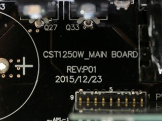
The TPG-1250D-T is based on CWT's fresh CST platform, which appears to feature a semi-digital design. It uses a couple of MCUs for APFC control and the digital interface. Some of the unit's protection capabilities are probably handled by one of the MCUs, too. We call this implementation semi-digital because the minor rails are addressed by an analog PWM controller. The same may also apply to the primary switchers, as we found an Infineon PWM controller on a board described as the "PWM Card". The +12V rail might be digitally controlled, though we can't be certain since we don't have the TPG-1250D-T's schematics. On top of that, the rail's less-than-tight load regulation raises some doubts. Without concrete information from CWT, we can only guess at what two MCUs actually do. But from the moment we failed to find an analog controller (that is to say there is no APFC controller), we could safely assume that one of the MCUs took over its role.

The main PCB is large, and the primary side's heat sinks are quite small. Meanwhile, there are no heat sinks on the secondary side. As CWT used to do in its high-end platforms, the +12V FETs are cooled by the PCB they're installed on and a pair of bush-bars. In order to save space, CWT uses a number of daughterboards. We do like that this platform employs spade terminals for connecting the AC receptacle to the PCB, meaning less desoldering work for us.


The transient filter starts at the AC receptacle with two Y caps. It continues on the main PCB with four more Y caps, two X ones, two CM chokes, and a small MOV. There is also an NTC thermistor for inrush current protection, which is supported by a bypass relay.


A dedicated heat sink hosts two Vishay LVB1560 bridge rectifiers, which combine to handle up to 30A of current.


The PSU uses an interleaved PFC converter, meaning that there are two APFC converters operating in parallel with a phase difference between them. This minimizes input/output current ripple and lowers conduction losses, increasing efficiency and doubling the effective switching frequency. Each APFC converter uses one Toshiba TK25N60X FET along with a SCS110AG boost diode. The bulk caps are provided by Chemi-Con and they have different capacities and voltage ratings. There is nothing wrong with a mixed capacity since the caps are installed in parallel. However, both capacitors should have the same voltage rating. The larger cap is only rated for up to 400V, which comes close to the APFC converter's 380VDC bus, while the other is rated at 420V.


This board hosts the primary and secondary MCUs (as they're described on the PCB). The primary MCU is a Texas Instruments UCD3138. It's probably the main PWM controller, and it appears to handle the APFC converters. The secondary MCU is a Microchip PIC32MX230F064D; it provides the USB interface, which connects the PSU to your motherboard. The Microchip MCU might also handle regulation of the +12V rail.


The primary switchers are four Alpha & Omega AOTF29S50 FETs arranged into a full-bridge topology. An LLC resonant converter is also used to lower their switching losses.


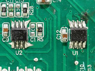
A daughterboard next to the main switchers houses a couple of Si8230BD drivers, each of which controls a pair of the primary FETs. On the same board, an Infineon PWM switching controller is also installed. Unfortunately, there is no way to identify it without completely removing the daughterboard.


Another daughterboard holds the 5VSB converter, which is connected to the modular PCB through a purple wire. The 5VSB regulator uses an On Bright OB5269CP IC, and we also spotted a M03N65D that's probably used for regulation on the same board.


The two parallel transformers are very close to the PCB that holds the FETs (12 Alpha & Omega AON6240s) responsible for regulating the +12V rail. Only four bus-bars are used for cooling these FETs and the PCB itself. This is probably why CWT used so many of them.


A large vertical PCB houses both DC-DC converters that generate the minor rails. Each converter uses three Sinopower SM3117NSUCs, and the common PWM controller is an ANPEC APW7159C. High-quality filtering caps, sourced by Chemi-Con, are installed in these converters.


Polymer caps from Apaq are used for filtering purposes on the secondary side. We also spotted several small Chemi-Con electrolytic caps. They're all rated at 105°C.


Many Apaq polymer caps are installed on the modular PCB for filtering. On the back of the same board, we noticed several thick wires that are routed/soldered on the front side of the PCB, transferring earth and power.

On the solder side of the main PCB we spot a supervisor IC, which provides some of the PSU's protection features. It is a Infinno ST9S313-DAG.

On the rear side of the PCB we also find an SPN5003 N-Channel logic enhancement mode power field effect transistor. According to its manufacturer, this component is suited for reducing vampire power. Close by is another IC, a Texas Instruments UCC27324 dual-MOSFET driver. The photo above clearly shows CWT's lousy soldering job.


The main PCB sports average soldering quality. We expected much better craftsmanship from CWT, especially in such a high-end PSU.


The fan is made by Hong Sheng and its model number is A1425L12S. This is a mid-speed fan supported by a relaxed profile, so it manages to offer quiet operation under tough conditions. According to Thermaltake, this fan uses a hydro-dynamic bearing. Moreover, there is a LED strip installed on the fan, which can be controlled through the DPSApp.
Thermaltake states that the fan's blades are designed for high static pressure to offer improved cooling. Moreover, anti-vibration rubber pads are used on the fan frame's four corners for lower noise output.
Current page: A Look Inside And Component Analysis
Prev Page Packaging, Contents, Exterior And Cabling Next Page Load Regulation, Hold-Up Time And Inrush CurrentStay on the Cutting Edge
Join the experts who read Tom's Hardware for the inside track on enthusiast PC tech news — and have for over 25 years. We'll send breaking news and in-depth reviews of CPUs, GPUs, AI, maker hardware and more straight to your inbox.
Aris Mpitziopoulos is a Contributing Editor at Tom's Hardware US, covering PSUs.
-
GPUEnthusiast I think those cables look straight ugly with three colors like that. In a windowed case, you won't even notice they're sleeved and it will instead look like an old style power supply with the rainbow wires, just really thick. I think they should stick with black and red, or just black. That yellow is faded too much and looks like it's for a banana themed build.Reply -
g-unit1111 Maybe it's me but I fail to grasp how an RGB ring on a PSU adds to it. Especially since most cases have bottom-mounted PSUs these days.Reply -
jimmysmitty Reply18420891 said:Maybe it's me but I fail to grasp how an RGB ring on a PSU adds to it. Especially since most cases have bottom-mounted PSUs these days.
It's all about them ground effects brah!!!!!
I agree though. Unless you have a very open bottom, most do not since most have a dust filter, it wont really show. I would expect a LED logo instead. -
turkey3_scratch This is a really great power supply! The transient response performance is top-notch. I really like it. The only thing I wish is for it to be a multirail design.Reply -
basroil Almost something I could recommend, if not for that horrible double line frequency oscillation in the 12V. I would have expected a digitally controlled system to be able to remove simple harmonics like that. Perhaps their controller algorithm isn't all that great?Reply -
powernod I was anxiously expecting this review due to CWT's new CST platform.Reply
Just like Aris said at the end of his review, i'm expecting to see how the smaller wattage models will perform.
The 1250 watt model seems like an excellent unit, and the only thing i disliked is the small output from the smaller rails ( 20A @5V &3.3V / 15A @5VSB ).
P.S. Once again, an excellent review from Aris!!