How To Build A Simple Raspberry Pi Pico Robot
This two-wheeled robot can move around a room autonomously.
Building robots is an awesome way to learn electronics and programming. We have the excitement of making something move, along with learning life-long coding skills that will help us create many different projects. Robots are made using two disciplines. The first is the engineering of building a chassis and connecting electronic components together. The second discipline is the code that reads the inputs, which is interpreted by the brain and then controls the motors.
While there are many robotics projects out there for regular Raspberry Pi, the Raspberry Pi Pico is a good choice because of its low cost, low power requirements and instant-on capability (no OS required). Below, we’ll show you how to build a simple, Pico-powered robot that navigates through a room by touch and uses Kitronik’s Pico Motor Driver to interface between the Pico and its DC motors.
For this we are going to assume that you already know how to get your Raspberry Pi Pico up and running with MicroPython and that you know how to solder.
For This Project You Will Need
- A Raspberry Pi Pico
- Kitronik Motor Driver Board
- Robot chassis
- 2 x DC TT motors with wheels
- A caster wheel for the front
- 1 x 4 AA Battery pack
- 4 x AA Batteries
- 1 x Microswitch / push button
- Soldering equipment
You can find the chassis, motor, battery pack and caster wheel together in an expensive package such as this one, which goes for around $13 on Amazon.
Building the Raspberry Pi Pico Robot
Your build will differ, depending on the robot chassis that you use but at the most basic level we have to connect the motors to the terminals of the driver board, connect the bump sensor and supply power from the batteries.
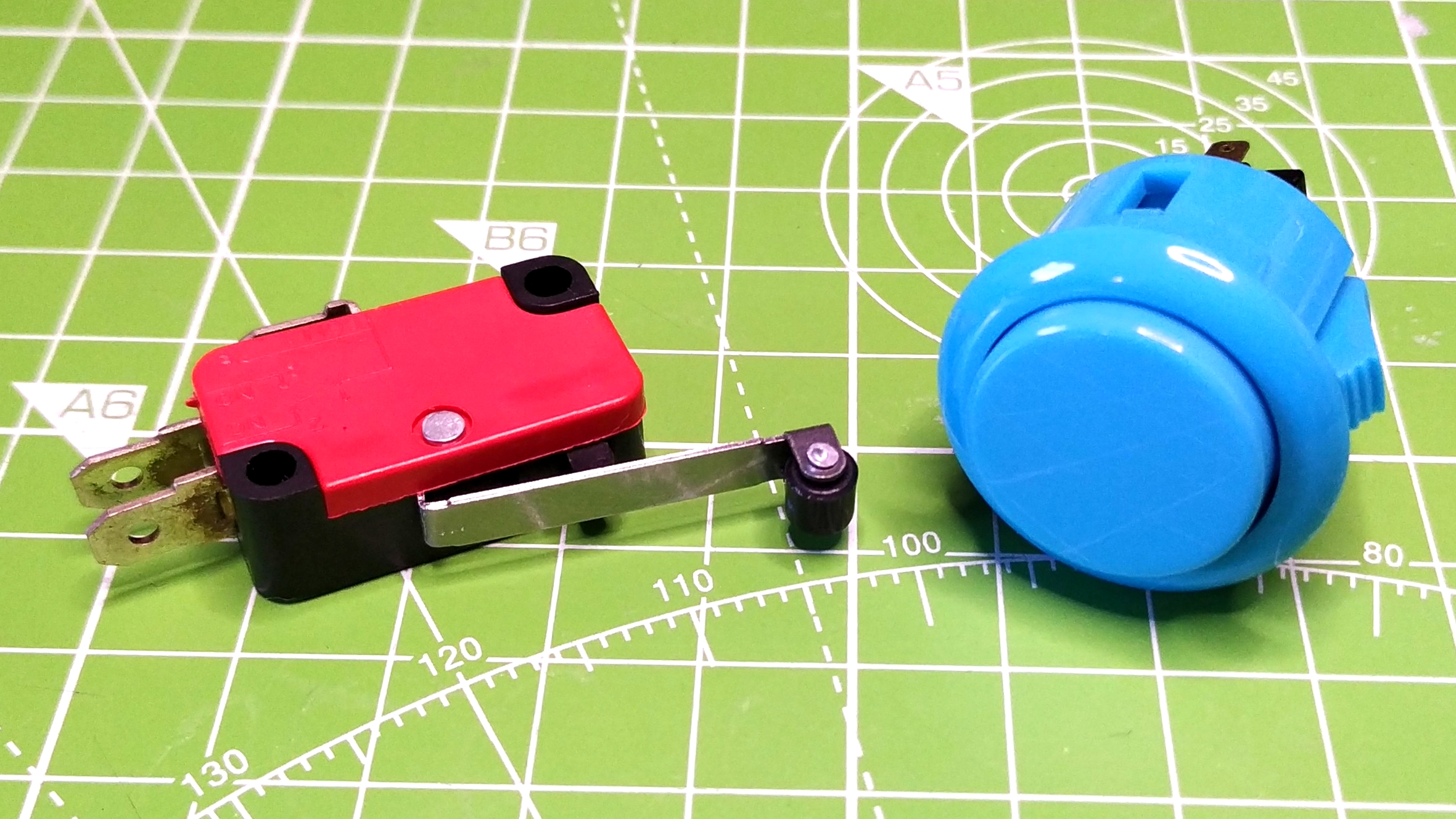
In our build we used a microswitch, commonly used in arcade joysticks and mice to give a clicky feedback, but you can use a simple pushbutton or an arcade button to achieve the same result.
Connecting the Components to Your Raspberry Pi Pico Robot
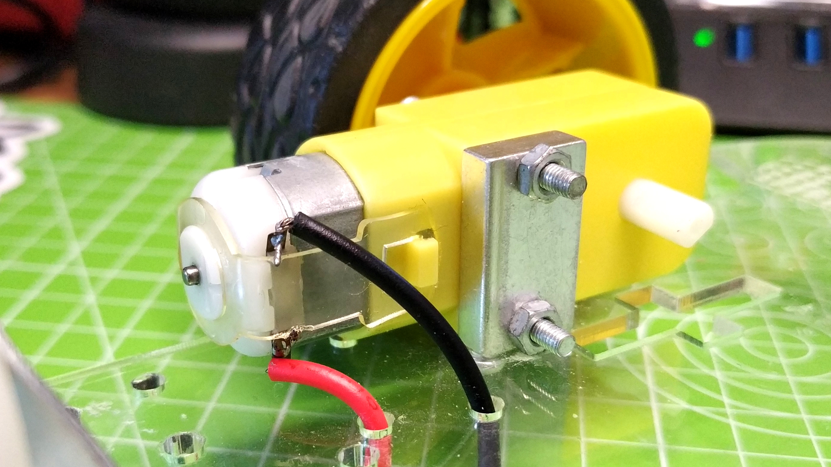
DC “TT” style motors (the kind in the yellow plastic housing) are common in the maker community. They work from around 5V to 9V and draw their power from the driver board.
Get Tom's Hardware's best news and in-depth reviews, straight to your inbox.
1. Insert the Pico into the female headers on the Kitronik board.
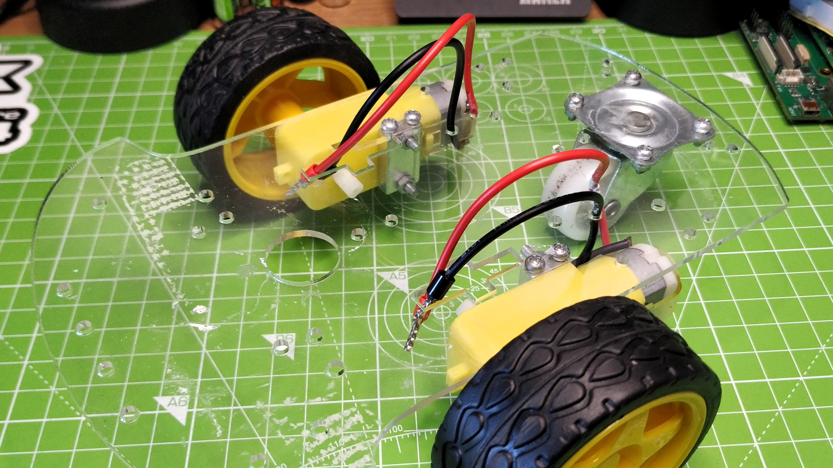
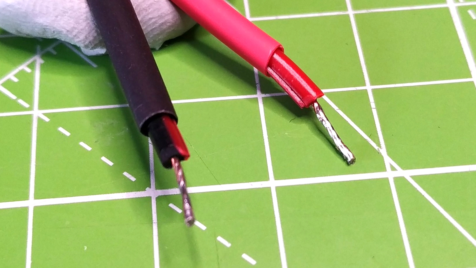
2. Strip the ends of four wires, leaving 10mm of bare wires on each end. Twist the wires and then flow a little solder onto each end. This is called “tinning” and it ensures that no stray ends cause a short. If your TT motors already have wires attached to them, only strip the opposite ends of those wires and skip to step 3.
3. Solder one end of each of the wires to the motors metal terminals.
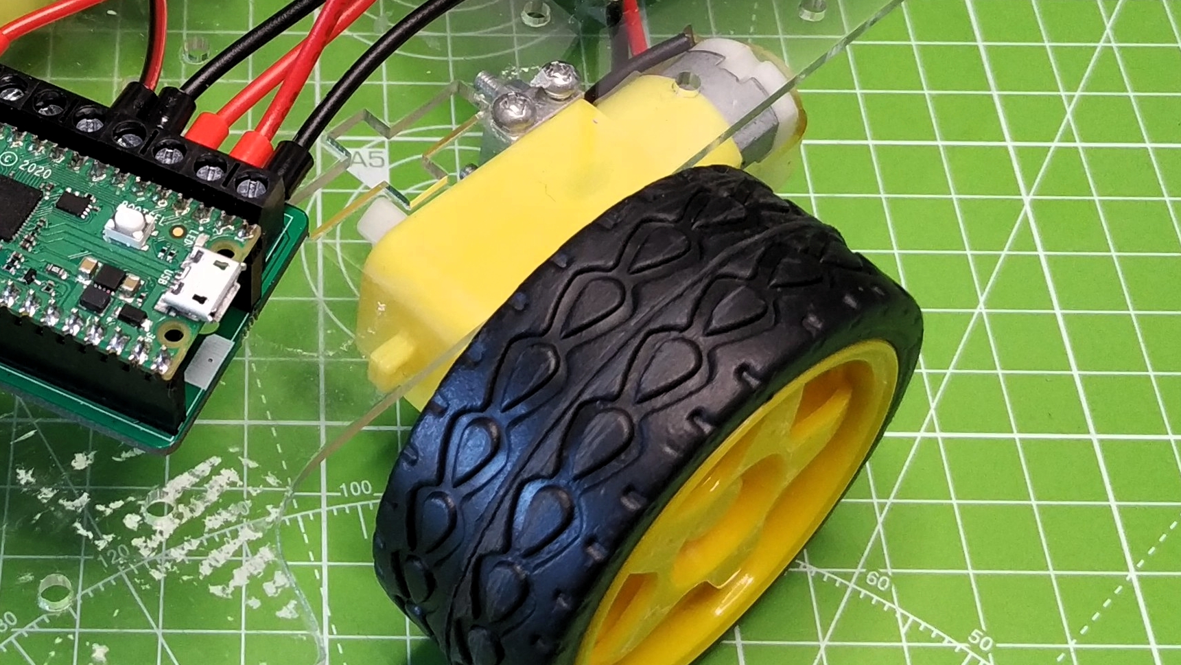
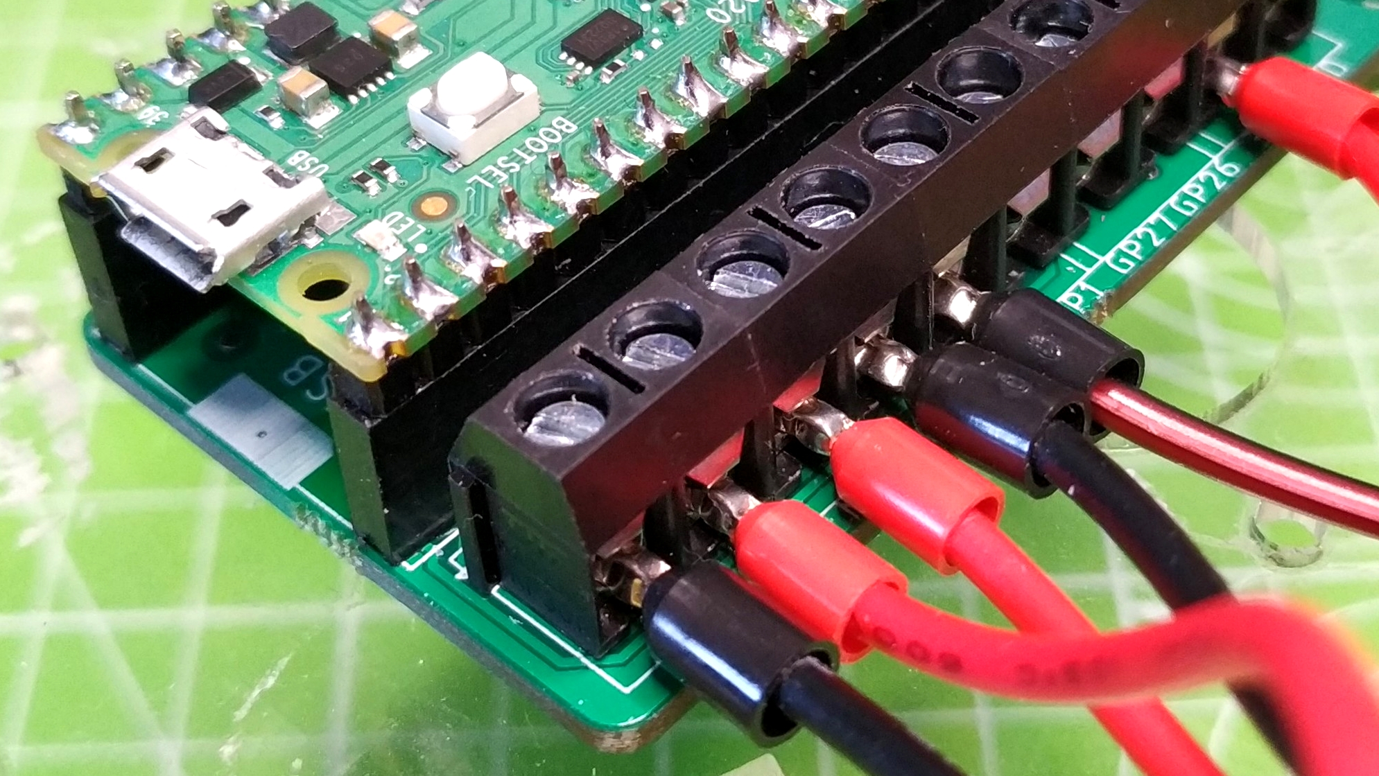
4. Insert the remaining ends into the Motor 1 and Motor 2 terminals on the Kitronik driver board. The wires from one motor will connect to a corresponding motor terminal. For example the left motor connects to the Motor 1 terminals, the right motor to Motor 2. You’ll notice that we added ferrules to our motor wires, this improves the strength and stability of the wires but it is entirely optional.
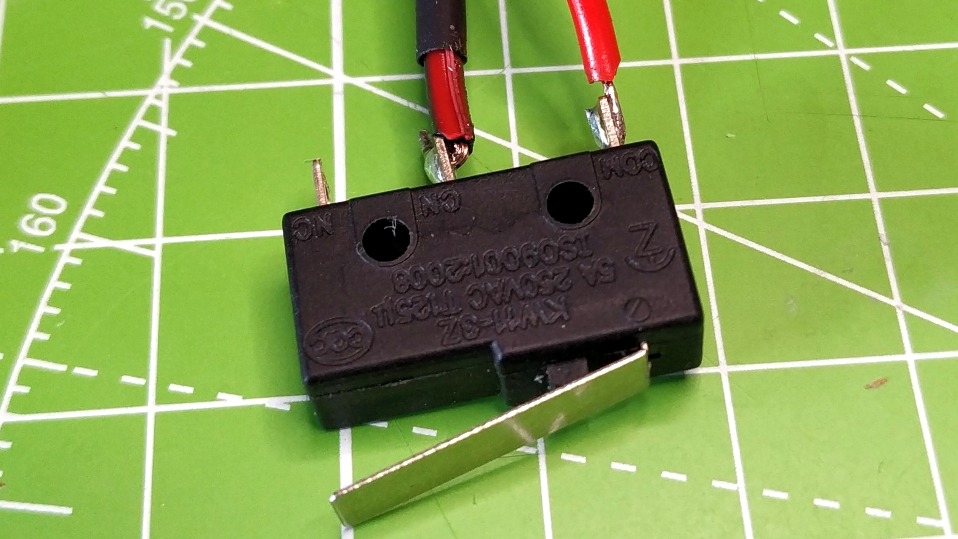
5. Solder two wires to the microswitch / button. One wire should be soldered to COM (Common) and the other to NO (Normally Open). This means that when the switch is pressed, the normally open circuit is closed, connecting the 3V terminal on the driver board to GP0.
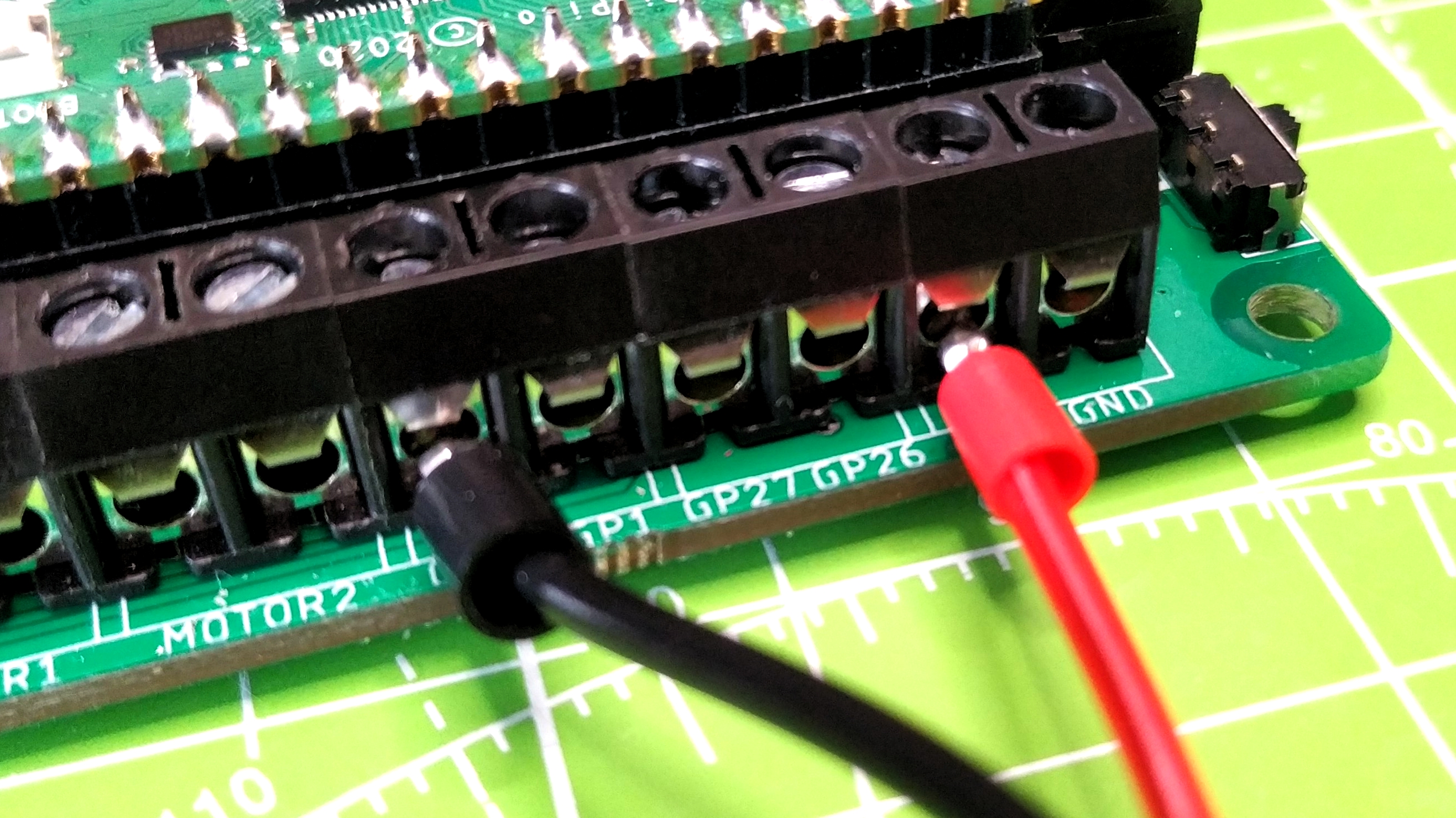
6. Insert the COM wire into the 3V terminal of the driver board, then insert the remaining wire into the GP0 terminal on the boad. Secure the switch to the front of the robot so that the metal contact is clear of the chassis.
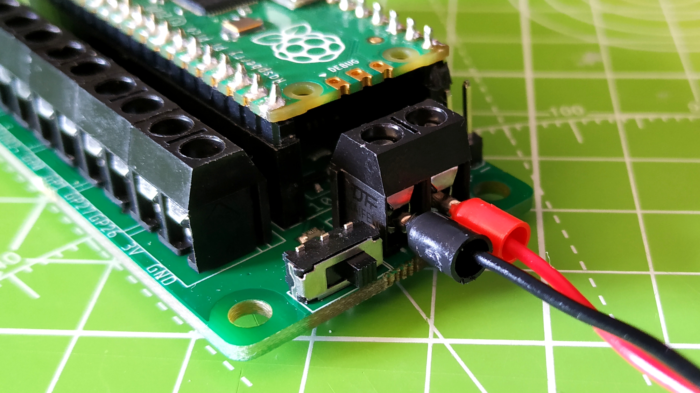
7. Connect your battery pack to power terminals. Ensure that you observe the correct polarity. The red wire is positive (+) and the black wire is negative (-). For now do not insert the batteries.
8. Secure the motor driver board and battery pack to the chassis.
Coding Your Raspberry Pi Pico Robot
Kitronik’s motor driver board has its own MicroPython library which abstracts the control of the motors and so we start by first installing that library. Please note that it is important that you do not have the power switch set to ON while the driver board is connected to your computer as this may damage the Pico or your computer.
1. Connect your Raspberry Pi Pico to your computer and open the Thonny application. Press STOP to ensure that the Pico is connected.
2. Copy the text of this motor driver library file.
3. Create a new file in Thonny and paste the text. Save the file as PicoMotorDriver.py to your Raspberry Pi Pico.
4. Create a new file for the project code.
5. Import two libraries. PicoMotorDriver and utime. PicoMotorDriver is the library that we just created and utime is used to pause and control the timings necessary for controlling the robot.
import PicoMotorDriver
import utime
6. Create two objects. The first, “board” is used to enable control of the motor driver board. The second, “forward_bumper” creates a connection between the driver board and the microswitch. We set this pin as an input, and ensure that the pin is pulled low (0V).
board = PicoMotorDriver.KitronikPicoMotor()
forward_bumper = machine.Pin(0, machine.Pin.IN, machine.Pin.PULL_DOWN)
7. Create a function called forward. This function has one argument and that is the speed at which we want the robot to move. Inside the function we have two lines of code. The first controls the motor connected to Motor 1. We specify the direction of travel as forwards “f”, and the speed variable is passed when the function is called.
The second line is almost identical, but with Motor 2 specified and the direction of travel set to reverse, as the motor will be seated on the opposite side of the robot. if the “f” and “r” values don’t work for you then swap them. But only change one set of values, for example the forward function, and test before moving on.
def forward(speed):
    board.motorOn(1, "r", speed)
    board.motorOn(2, "f", speed)
8. Create another function for reverse control.
def reverse(speed):
    board.motorOn(1, "f", speed)
    board.motorOn(2, "r", speed)
9. Create two more functions for moving the robot left and right. For this we need the motors to work in opposing directions so that the robot turns on the spot.
def left(speed):
    board.motorOn(1, "f", speed)
    board.motorOn(2, "f", speed)

def right(speed):
    board.motorOn(1, "r", speed)
    board.motorOn(2, "r", speed)
10. Create a final function to stop the robot.
def stop():
    board.motorOff(1)
    board.motorOff(2)
11. Add a five second delay to the code. This delay will give us the time to place the robot on the floor and move out of its way.
utime.sleep(5)
12. Create a while True loop to continuously run the code.
while True:
13. Inside the loop, add a conditional test. This test will check the GPIO pin used for the bumper microswitch. If the robot has bumped into an object, then the switch is closed, connecting the 3V terminal to GP0 and changing the value from 0 to 1.
if forward_bumper.value() == 1:
14. Write code for what happens if the robot bumps into something. On bumping, it will first print a message to the Python shell. Then it will use the reverse function at 75% power for one second. We then stop, print another message to the shell before turning left at 75% power for one second. The robot then stops.
print("Reverse")
        reverse(75)
        utime.sleep(1)
        stop()
        print("Left")
        left(75)
        utime.sleep(1)
        stop()
15. Add an else condition for when the robot is just moving forward. This will print a message to the Python shell, then using the forward function, set the speed to 75% and set the code to wait five seconds, which will move the robot forwards for five seconds.
    else:
        print("Forward")
        forward(75)
        utime.sleep(5)
16. Save the code to your Raspberry Pi Pico as main.py, this will force the code to run when the Pico is powered on.
Complete Code Listing
import PicoMotorDriver
import utime

board = PicoMotorDriver.KitronikPicoMotor()
forward_bumper = machine.Pin(0, machine.Pin.IN, machine.Pin.PULL_DOWN)

def forward(speed):
    board.motorOn(1, "r", speed)
    board.motorOn(2, "f", speed)

def reverse(speed):
    board.motorOn(1, "f", speed)
    board.motorOn(2, "r", speed)

def left(speed):
    board.motorOn(1, "f", speed)
    board.motorOn(2, "f", speed)

def right(speed):
    board.motorOn(1, "r", speed)
    board.motorOn(2, "r", speed)

def stop():
    board.motorOff(1)
    board.motorOff(2)

utime.sleep(5)
while True:
    if forward_bumper.value() == 1:
        print("Reverse")
        reverse(75)
        utime.sleep(1)
        stop()
        print("Left")
        left(75)
        utime.sleep(1)
        stop()
    else:
        print("Forward")
        forward(75)
        utime.sleep(5)
Place your robot on the floor and get ready to chase it around the room as it bumps and navigates your home using nothing more than a simple switch.

Les Pounder is an associate editor at Tom's Hardware. He is a creative technologist and for seven years has created projects to educate and inspire minds both young and old. He has worked with the Raspberry Pi Foundation to write and deliver their teacher training program "Picademy".
