Create a Raspberry Pi Light Show With Analog Inputs
Learn how to create colorful light effects with your Raspberry Pi
The Raspberry Pi may be a great platform for learning, but one major thing it can’t do out of the box is use analog electronic components. That leaves everything from analog joysticks to potentiometers off limits by default, but fortunately adding an expensive chip solves the problem. The MCP3008 ADC (Analog to Digital Converter) is used to connect analog electronics to the Raspberry Pi’s 40 GPIO pins, enabling you to use all kinds of additional components.
To show you how to take advantage of analog-to-digital conversion and how to make a fun light show, we’ve created a project that will read three potentiometers and use these dials to control the color of an Adafruit NeoPixel. Here’s how to create a colorful Raspberry Pi light show using analog input.
What You Need to Make a light show with your Raspberry Pi:
- Raspberry Pi. Any model can be used
- Raspberry Pi OS on an 8GB+ micro SD card
- MCP3008 Analog to Digital (A/D) converter used to read analog signals and convert them for the Pi to understand
- Adafruit NeoPixels WS2812B LEDs. We used a 12 pixel LED ring from Adafruit
- Soldering equipment. This is only required to solder jumper wires to the NeoPixels.
- A 400 point of larger breadboard. Used to build the circuit
- 3x 10k potentiometers. These are the dials used as inputs
- 6x Male to female jumper wires
- 13x Male to male jumper wires
How to Create a Rasperry Pi Light Show with Analog Inputs
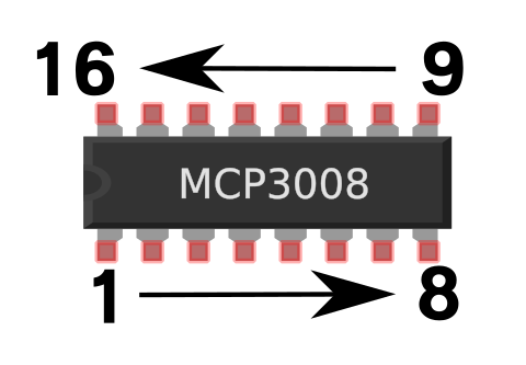
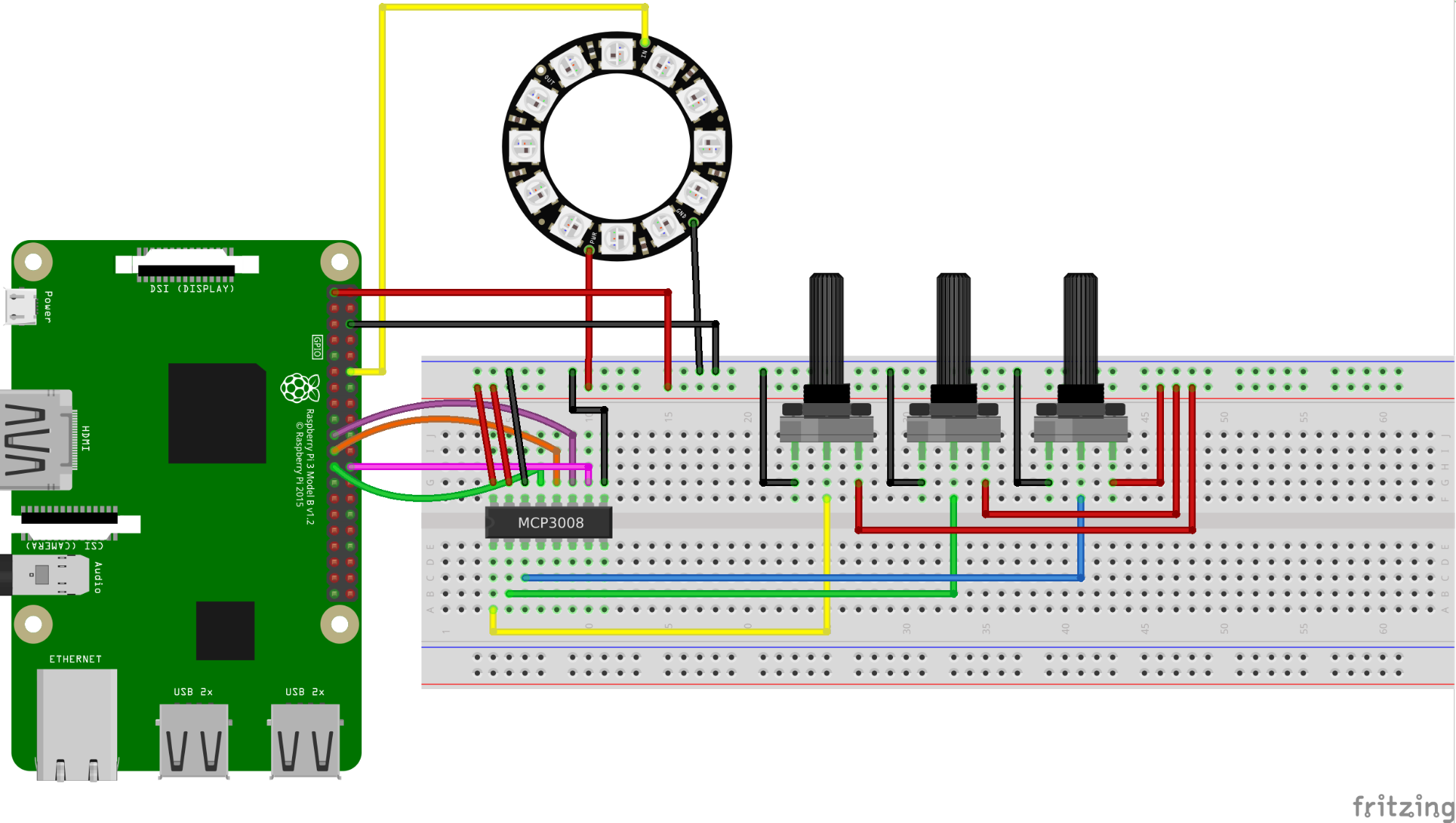
1. Insert the MCP3008 into the breadboard so that the pins straddle the central cut out. The notch on the chip should face the short end of the breadboard. The 16 pins of the MCP3008 start with 1 in the bottom left corner, then we count along to 8 in the bottom right. Pin 9 is in the top right corner and finally pin 16 in the top left.
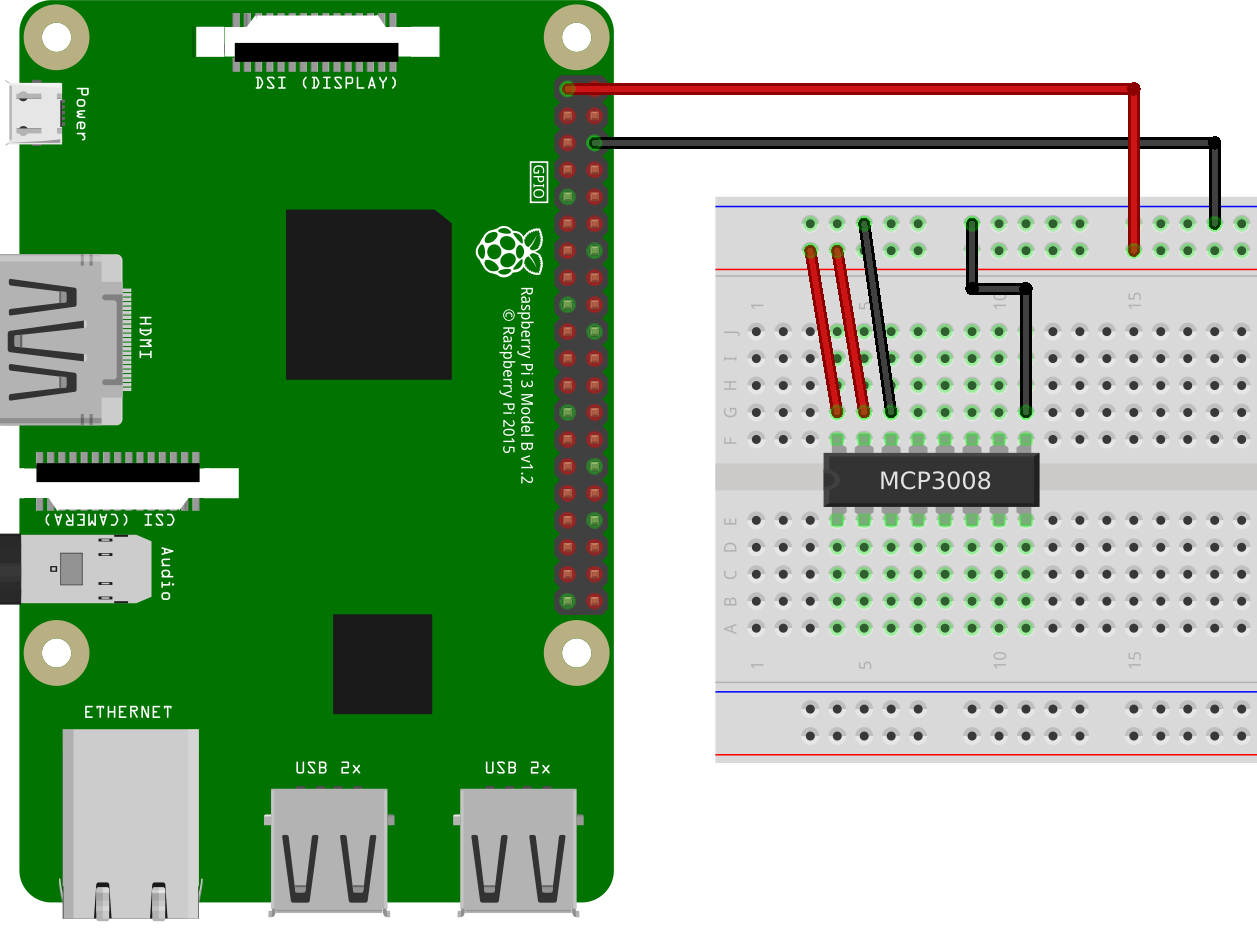
2. Connect the MCP3008 to the Raspberry Pi GPIO using the female to male jumper wires. First female to male wires to connect the 3.3V and GND pins to the + and - rails of the breadboard. Then use male-to-male wires to connect the rails to the MCP3008 pins for power and GND.
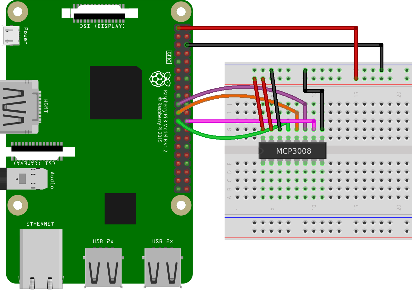
3. Connect the MCP3008 to the Raspberry Pi using female to male jumper wires.
| Wire Color | MCP3008 | Raspberry Pi GPIO |
|---|---|---|
| Pink | 10 | GPIO 08 |
| Purple | 11 | GPIO 10 |
| Orange | 12 | GPIO 09 |
| Green | 13 | GPIO 11 |
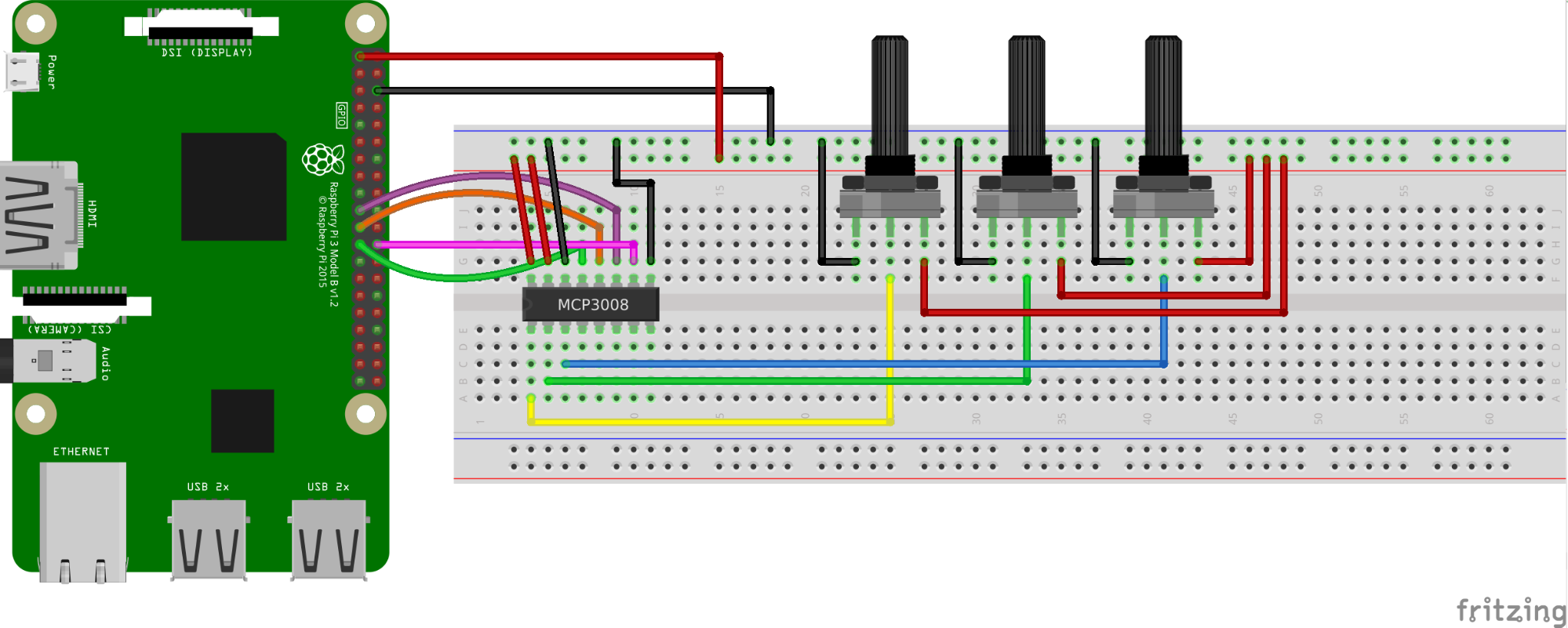
4. Insert the potentiometers and connect them to the MCP3008 using male to male jumper wires.
Get Tom's Hardware's best news and in-depth reviews, straight to your inbox.
5. Solder three wires to the Adafruit NeoPixels. PWR, GND and In. PWR connects to the + rail on the breadboard, GND to the - rail. “IN” is connected to GPIO 18 on the Raspberry Pi.
6. Edit the /boot/config.txt file.
sudo nano /boot/config.txt7. Add this line to the bottom of the file. It will enable the GPIO to talk to the NeoPixels but it will disable audio output via the headphone jack. Press CTRL + X, Y and Enter to exit when done. Reboot the Pi for the changes to take effect.
hdmi_force_hotplug=18. Install the Python 3 modules for NeoPixels.
sudo pip3 install rpi_ws281x adafruit-circuitpython-neopixel9. Open the Thonny IDE, found in the Programming menu.
10. Add the following lines to import modules that enable the code to work with NeoPixels, pause the code, and use the MCP3008 board.
import board
import neopixel
from time import sleep
from gpiozero import MCP3008
11. Create three variables r,g,b which will store the raw values output by the MCP3008.
r = MCP3008(channel=0)
g = MCP3008(channel=1)
b = MCP3008(channel=2)
12. Create an object called pixels. This will enable the Python code to work with the NeoPixels. To this object we pass the GPIO pin which is being used, D18, and the number of NeoPixels in the chain / ring, 16.
pixels = neopixel.NeoPixel(board.D18, 16)13. Create a while True: loop which will continuously run the code.
while True:14. Create three variables, red, green and blue which will store the returned value from the potentiometer. This value is between 0.0 and 1.0 and to convert it into something the NeoPixels can understand we multiply the value by 255.
        red = round(r.value * 255)
	green= round(g.value * 255)
	blue = round(b.value * 255)
15. Print the returned values to the Python shell.
print(red,green,blue)16. Create a for loop which will update all 16 pixels in the ring to show the current color mix.
        for i in range(16):
    	pixels[i] = (red, green, blue)
17. Add a 0.1 second pause to the code.
sleep(0.1)18. Save the code as analog-inputs.py.
19. Run the code using sudo in a terminal.
sudo python3 analog-inputs.py20. Turn the potentiometers to control the color of the NeoPixels.
Complete Code Listing
Here is all of the code used in this project.
import board
import neopixel
from time import sleep
from gpiozero import MCP3008

r = MCP3008(channel=0)
g = MCP3008(channel=1)
b = MCP3008(channel=2)


pixels = neopixel.NeoPixel(board.D18, 16)


while True:
    red = round(r.value * 255)
    green= round(g.value * 255)
    blue = round(b.value * 255)
    print(red,green,blue)
    for i in range(16):
        pixels[i] = (red, green, blue)
    sleep(0.1)
MORE: Raspberry Pi Tutorials
MORE: Best Raspberry Pi HATs
MORE: Best microSD Cards for Raspberry Pi

Les Pounder is an associate editor at Tom's Hardware. He is a creative technologist and for seven years has created projects to educate and inspire minds both young and old. He has worked with the Raspberry Pi Foundation to write and deliver their teacher training program "Picademy".
-
SonoraTechnical You need to enable the SPI Interface in the RaspberryPI as well. The omission of any mention of SPI in this article is odd.... It's what allows the 'I/O' expansion in this tutorial, that is the ability to accept analog inputs. The MCP3008 is an A/D converter, which relays the info back to the RaspberryPi over the SPI Interface.... similar to what you might do for I/O expansion over an UART or I2C interface.Reply -
biglesp Reply
Hello, thanks for your comment.SonoraTechnical said:You need to enable the SPI Interface in the RaspberryPI as well. The omission of any mention of SPI in this article is odd.... It's what allows the 'I/O' expansion in this tutorial, that is the ability to accept analog inputs. The MCP3008 is an A/D converter, which relays the info back to the RaspberryPi over the SPI Interface.... similar to what you might do for I/O expansion over an UART or I2C interface.
We are using the GPIO Zero Python 3 module to handle communication with the MCP3008 and this has two SPI modes.
A software SPI which is always available and needs no further configuration, but it is much slower than hardware.
A hardware SPI which is enabled when the SPI kernel module is enabled via raspi-config or the GUI Raspberry Pi configuration tool.GPIO Zero Documentation for SPI
https://gpiozero.readthedocs.io/en/stable/api_spi.html
I hope that this clears the issue for you. Many thanks for reading.
