How To Build a Raspberry Pi Pico W Web App With Anvil
Build interactive web apps with a Raspberry Pi Pico W
The Raspberry Pi Pico W packs a ton of functionality into a very affordable package. For just $6 we get the same dual core Arm Cortex M0+ CPU running at 133 MHz, 264KB of RAM and 2MB of flash memory as the original Raspberry Pi Pico. But we also get a 2.4 GHz capable Wi-Fi chip, all in the same DIP package.
The inclusion of Wi-Fi is the biggest draw. We have a simple and cheap microcontroller, with enough horsepower to accomplish many projects typically reserved for more powerful and expensive Raspberry Pis, such as the Raspberry Pi 4 and the Raspberry Pi Zero 2 W.
Wi-Fi enables Internet of Things (IoT) projects and for that we need a secure and easy-to-use means to write projects. Step forward Anvil, which, offers Pico W firmware that trivialises IoT projects and takes advantage of its uplink service. With Anvil and the uplink service, we can easily write code on the web that will interact with the $6 Wi-Fi enabled micro-controller.
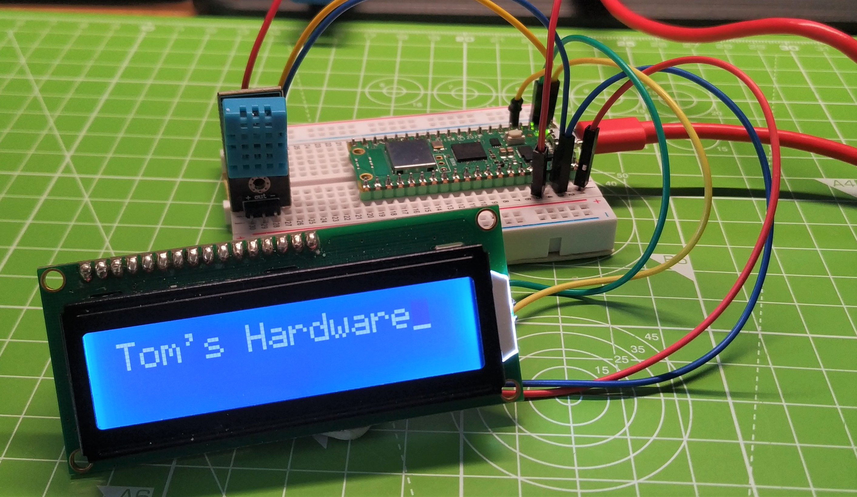
In this how-to we shall write a project that enables two-way communication between the Raspberry Pi Pico W and Anvil’s servers in the cloud. We will send live sensor data from the Raspberry Pi Pico W to a web app on Anvil’s servers. We shall also send messages from the app to the Raspberry Pi Pico W, to be displayed on a small LCD display.
For this project you will need
- Raspberry Pi Pico W
- An I2C LCD display
- A DHT11 Temperature Sensor
- 4x Female to male jumper wires
- 3x Male to Male jumper wires
- 1x Half size breadboard
Building the Circuit for Anvil on a Pico W
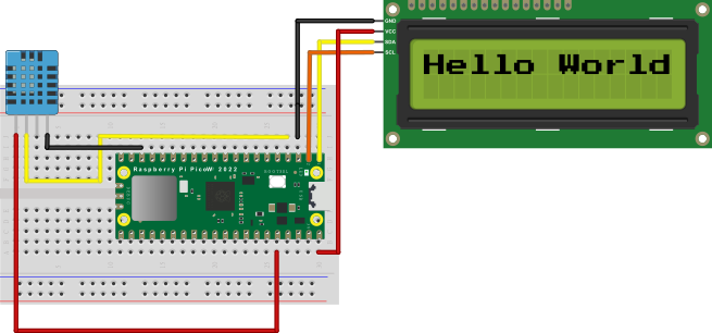
The circuit for this project consists of one input device, a DHT11 temperature sensor, and one output, an LCD screen connected over I2C. The DHT11 will measure the temperature and humidity, which is then sent to Anvil to be displayed in a web app. The LCD screen will display short messages, typed into the same Anvil web app.
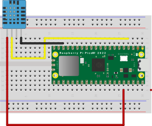
The DHT11 has four pins. Looking from the front (the blue “cage”) we connect to the Raspberry Pi Pico W as follows
Pin 1: (Red Wire) Connect VCC to 3V3(OUT) of the Pico W.
Get Tom's Hardware's best news and in-depth reviews, straight to your inbox.
Pin 2: (Yellow Wire) Connect Data out to GP4 of the Pico W.
Pin 3: No connection.
Pin 4: (Black Wire) Connect GND to GND of the Pico W.
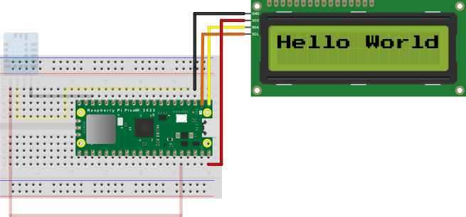
The LCD has four connections.
GND: (Black Wire) Connect to any GND on the Pico W.
VCC: (Red Wire) Connect to VBUS on the Pico W.
SDA: (Yellow Wire) Connect to I2C0 SDA on the Pico W.
SCL: (Orange Wire) Connect to I2C0 SCL on the Pico W.
Check your wiring before moving onwards.
Setting up the Raspberry Pi Pico W
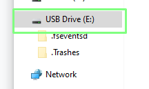
Anvil uses a custom firmware image for the Raspberry Pi Pico W, an image which simplifies connecting the Pico W to Anvil’s services. The firmware is based on MicroPython, with the Pico W appearing as a USB drive with two files (boot.py and main.py). Before we can write any code for our project we first need to flash the custom firmware to the Pico W, and connect to our Wi-Fi.
1. Download the custom Raspberry Pi Pico W firmware from Anvil.
2. Push and hold the BOOTSEL button on the Pico, then connect to your computer using a micro USB cable. Release BOOTSEL once the drive RPI-RP2 appears on your computer.
3. Drag and drop the Anvil UF2 file onto the RPI-RP2 drive. The Raspberry Pi Pico will reboot and will now run MicroPython.
4. Open File Explorer and navigate to the new USB drive. Anvil’s firmware uses MicroPython, and presents itself as a USB drive, similar to CircuitPython.
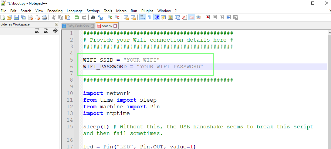
5. Open boot.py in a text editor and change the values for WIFI_SSID and WIFI_PASSWORD to match your setup. Save and exit when done. This file contains all of the Python code which is run at boot. In this case, it will connect to our Wi-Fi AP and flash the Pico W’s onboard LED if there is no connection.
Your Raspberry Pi Pico W should now connect to your Wi-Fi and the onboard LED should stop blinking. A static LED means we are connected to the Wi-Fi and ready for our project.
Code for the Raspberry Pi Pico
1. Install Thonny on your computer if you haven’t done so already. Follow the steps in our article on how to set up a Raspberry Pi Pico W. Thonny is an easy to use Python editor which has been configured to work with the Raspberry Pi Pico.
2. Create a new blank file in Thonny.
3. Open this link and copy the text from the page.
4. Save the file to the Raspberry Pi Pico as lcd_api.py
5. Create another blank file.
6. Open this link and copy the text from the page.
7. Save the file to the Raspberry Pi Pico as pico_i2c_lcd.py These two files enable the use of the I2C LCD screen with the Raspberry Pi Pico W.
8. Open main.py, found on the Raspberry Pi Pico W drive.
9. Delete the contents of main.py.
10. Import three modules of pre-written code. The first is anvil.pico and this enables our Pico W to connect to Anvil’s servers. Next, uasyncio creates an asynchronous scheduler on the Pico W, we need this for running concurrent functions in our code. The third module is machine, and from that we need the Pin (GPIO pins) and I2C classes to communicate with the GPIO and LCD screen.
import anvil.pico
import uasyncio as a
from machine import Pin, I2C
11. Import three more modules. The time module enables control over the pace of our code. The dht module is specific for the DHT11 (and DHT22) temperature sensor and acts as an easier means to get data from the sensor. The pico_i2c_lcd enables our code to use the LCD display.
from time import sleep
import dht
from pico_i2c_lcd import I2cLcd
12. Create an object, i2c, to create a connection from our code to the I2C bus. I2C0 has SDA at pin 0 and SCL at pin 1.
i2c = I2C(0, sda=Pin(0), scl=Pin(1), freq=400000)13. Create an object I2C_ADDR to store the I2C address of the LCD display. This line of code will scan the I2C bus for the address and store it in the object.
I2C_ADDR = i2c.scan()[0]14. Create an object, lcd, to make a connection between our code and the LCD display. This uses the i2c object, the I2C address, and sets the display to have 2 lines and 16 characters. There are screens with differing sizes, so adjust this to match your screen.
lcd = I2cLcd(i2c, I2C_ADDR, 2, 16)15. Turn the LCD backlight on, and set the cursor to blink. The backlight is essential as the screen can be hard to read. The flashing cursor, that’s more of a retro vibe.
lcd.backlight_on()
lcd.blink_cursor_on()
16. Create an object UPLINK_KEY, and for now store blank data. This is where our Anvil Pico Uplink key will be stored. We will get that information later.
UPLINK_KEY = " “17. Create an object, sensor, to store a connection from our code to the DHT11 temperature sensor. Using this object we can interact with the DHT11 and get data.
sensor = dht.DHT11(Pin(2)) 18. Use a Python decorator to instruct Anvil that the next function is callable from the Anvil web app. Decorators are a means to add additional functionality to a function, without impacting the function.
@anvil.pico.callable(is_async=True)19. Create a function, dht11data which will work with the scheduler.
async def dht11data():20. Take a reading with the DHT11. We need to do this in order to get the raw data. Note that we are now inside the function and our code is now indented to show that it belongs to the function.
sensor.measure()21. Create two objects, temp and hum to store the temperature and humidity readings from the DHT11. The round() function rounds the values to one decimal place.
   temp = round(sensor.temperature(),1)
   hum = round(sensor.humidity(),1)
22. Create an object, data, which will store a string / sentence containing the temperature and humidity data using string formatting to insert the data into the sentence.
data = ("Temperature: {}°C Humidity: {:.0f}% ".format(temp, hum))23. Print the sentence to the Python shell, and then use return to output the sentence for Anvil to read. These lines are the last for this function.
   print(data)
   return data
24. Create another decorator, this time for a function that will show messages on the LCD screen. The message is passed as an argument to the function (message).
@anvil.pico.callable(is_async=True)
async def show_message(message):
25. Use a for loop to flash the LCD backlight three times. This will get our attention for an incoming message. The backlight is simply turned on and off, with a short pause between each.
   for i in range(3):
       lcd.backlight_on()
       sleep(0.2)
       lcd.backlight_off()
       sleep(0.2)
26. Turn the backlight on. We need the backlight to see the text.
lcd.backlight_on()27. Write the message to the LCD display, and then pause for ten seconds. Long enough to read the message. Then clear the LCD display. This is the end of this function.
   lcd.putstr(message)
   sleep(10)
lcd.clear()
28. Connect the Pico W to Anvil’s servers using your uplink key. We will get the key later in this project.
anvil.pico.connect(UPLINK_KEY)29. Save the code as main.p
Anvil Code for Raspberry Pi Pico W
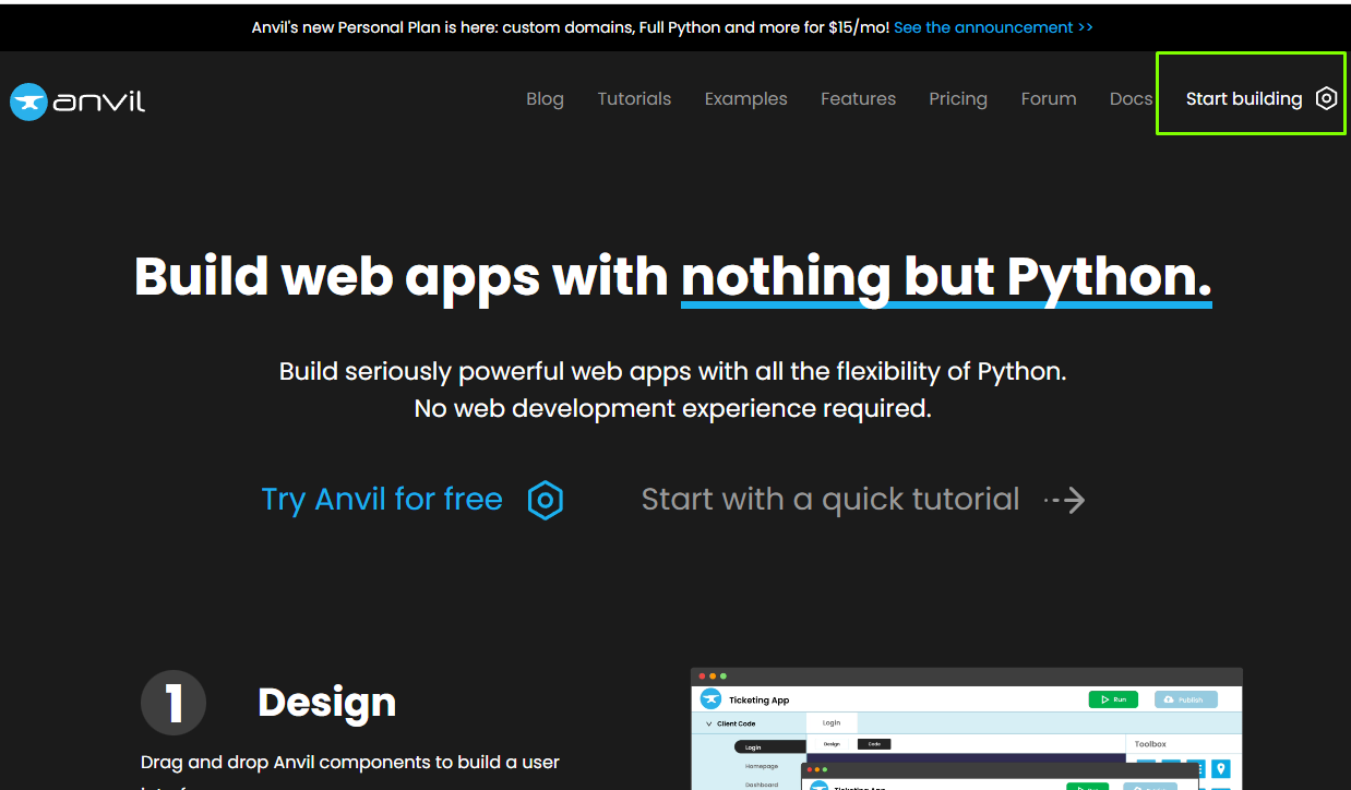
1. Go to the Anvil website and click on Start Building.
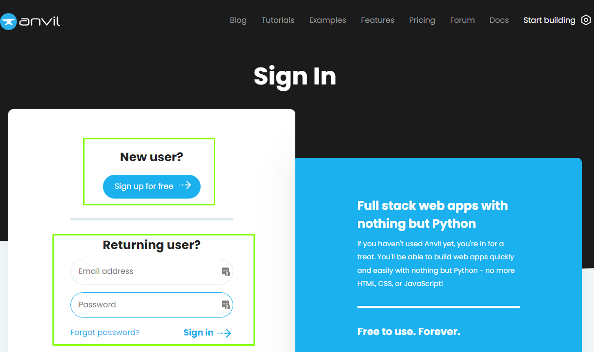
2. Sign in or sign up for a free account.
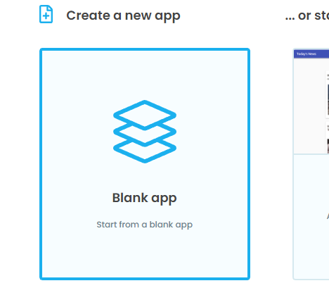
3. Create a new blank app.
4. Select Material Design Theme.
The Anvil editor is split into two sections. Design and Code. In the Design section we create the user interface for our app. In Code, we give the application the functionality that we require. We’ll start by adding elements to the app, and then we shall add functionality to the elements.
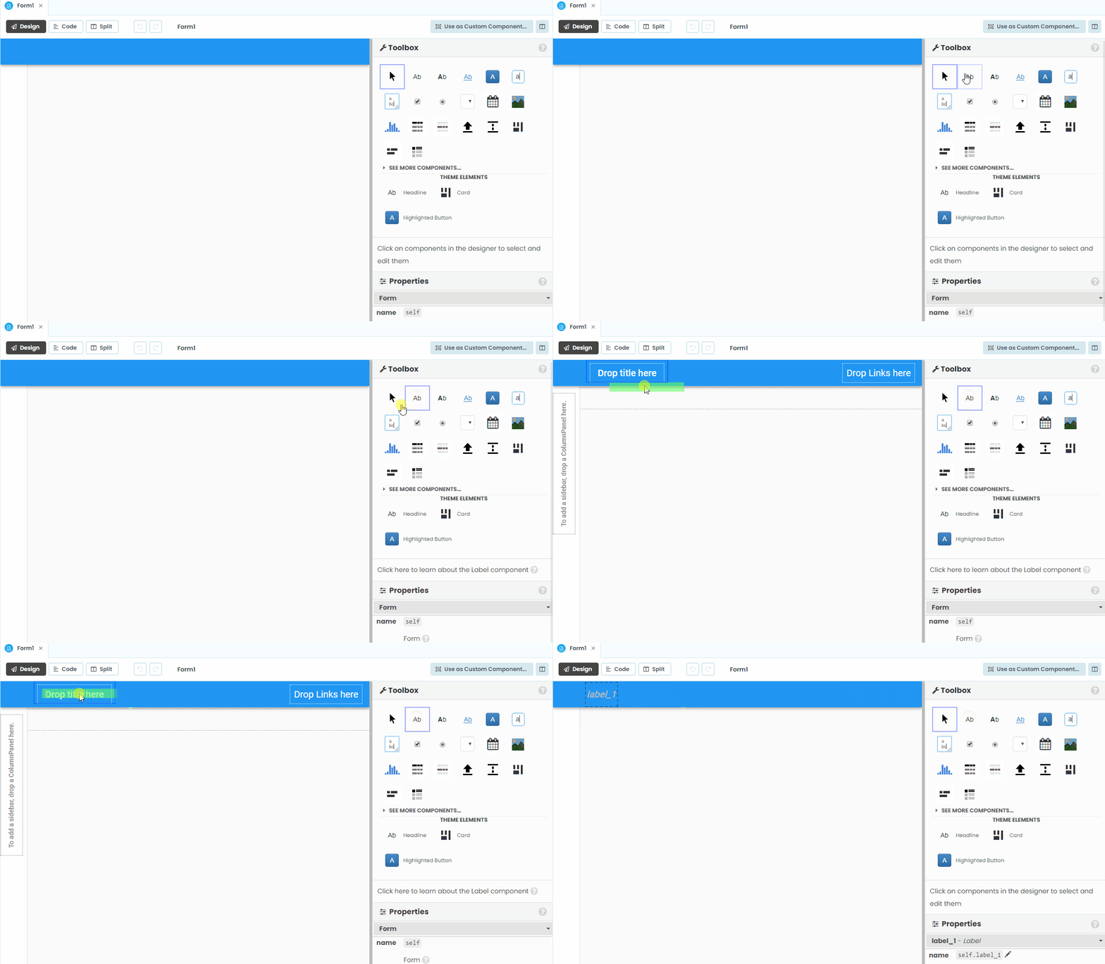
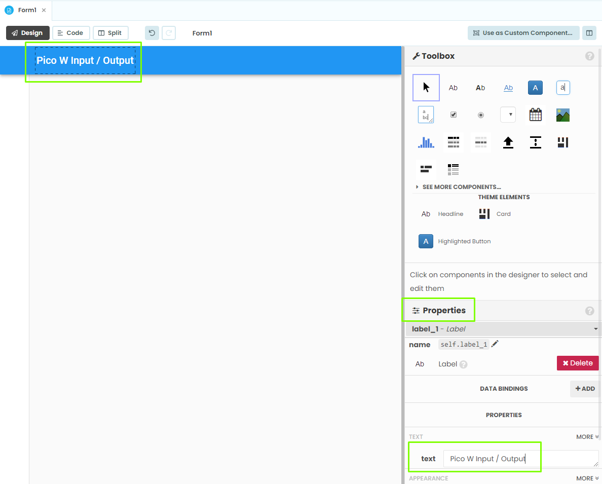
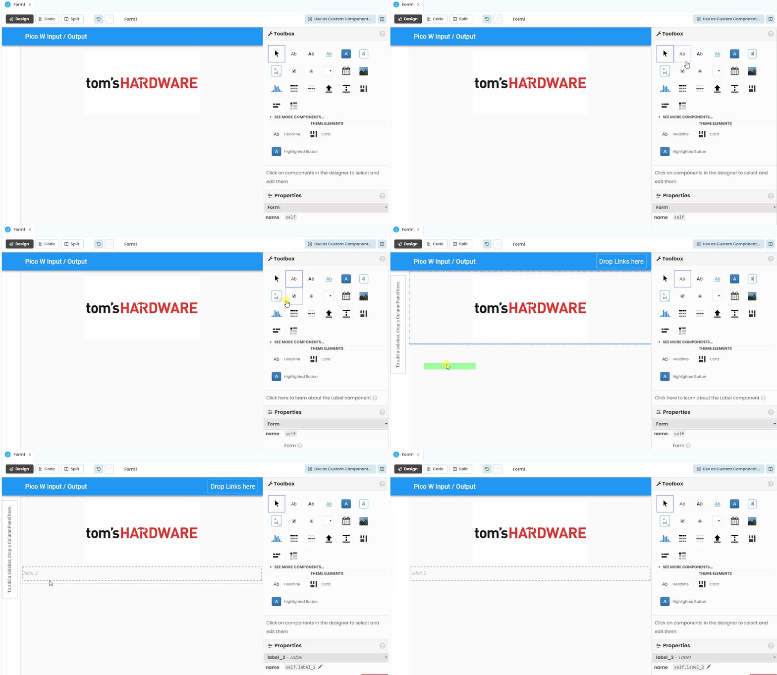
1. From the Toolbox, drag a Label tool and place it on “Drop title here.”
2. Change the label text via the text field in the properties menu.
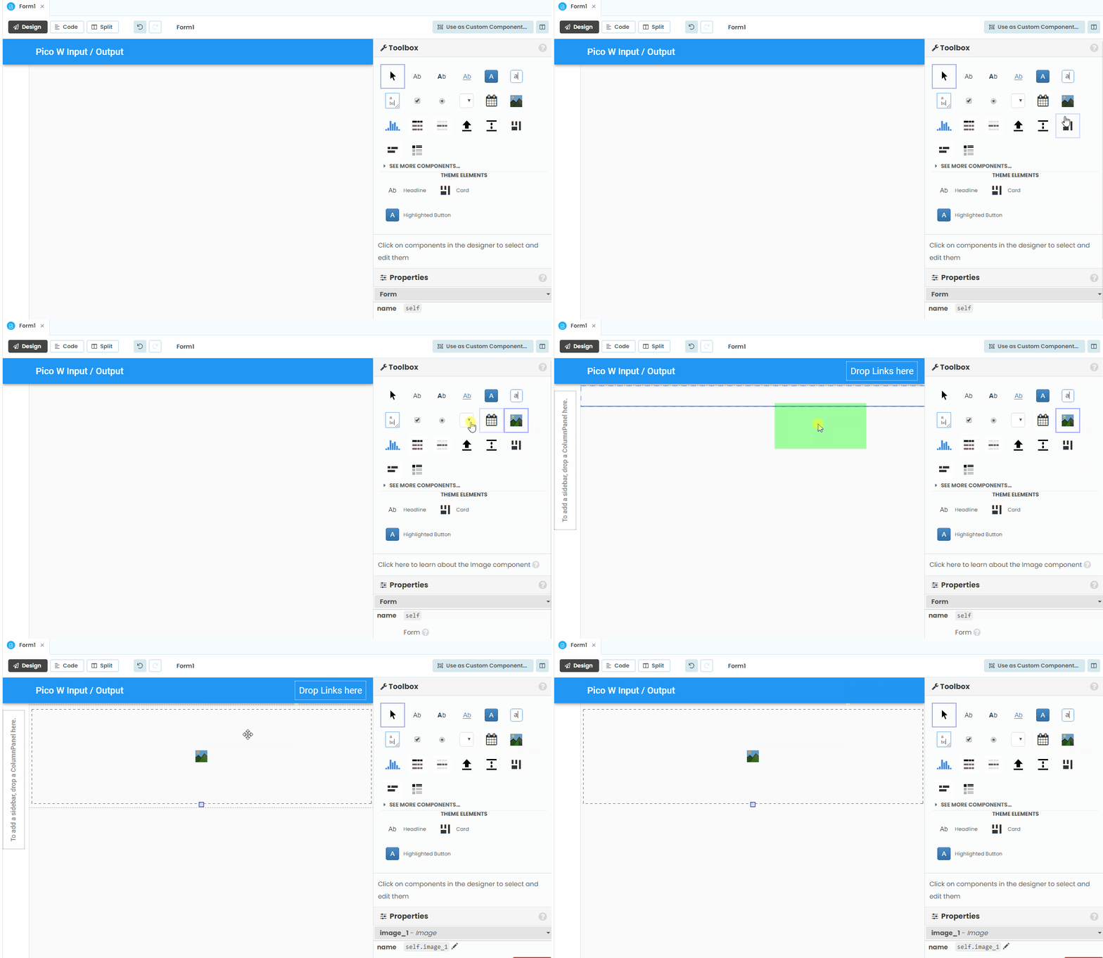
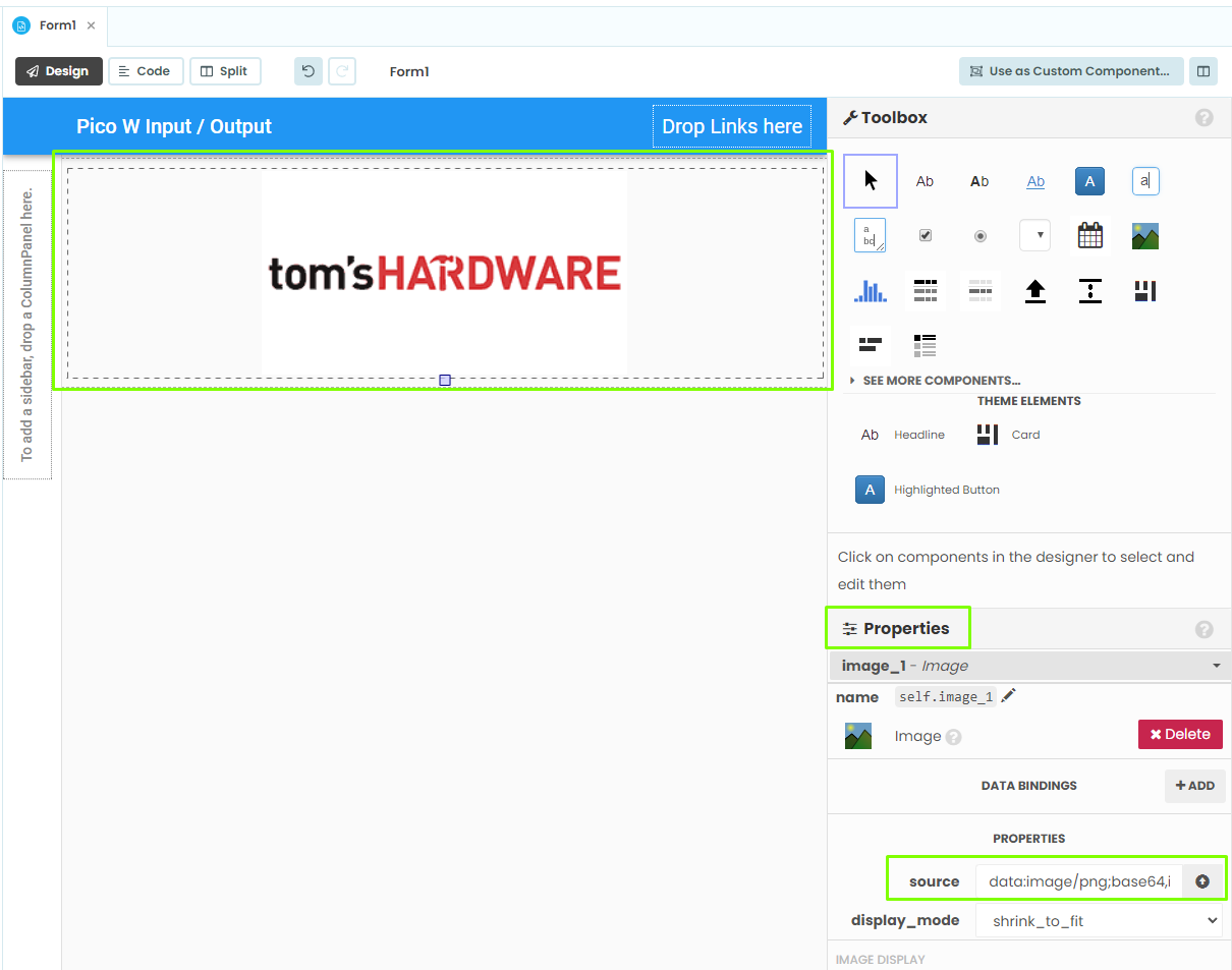
3. Drag an image tool into the form. With this we can add a logo or image to our project.
4. From Properties, select Source and select the image for your application.
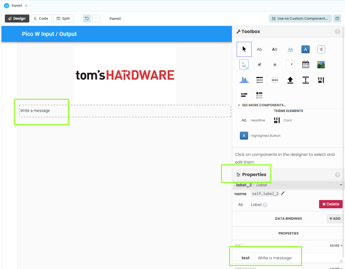
5. From the Toolbox, drag another label and place it under the image. This will become an instruction to the user.
6. Write an instruction to the user, in this case to write a message.
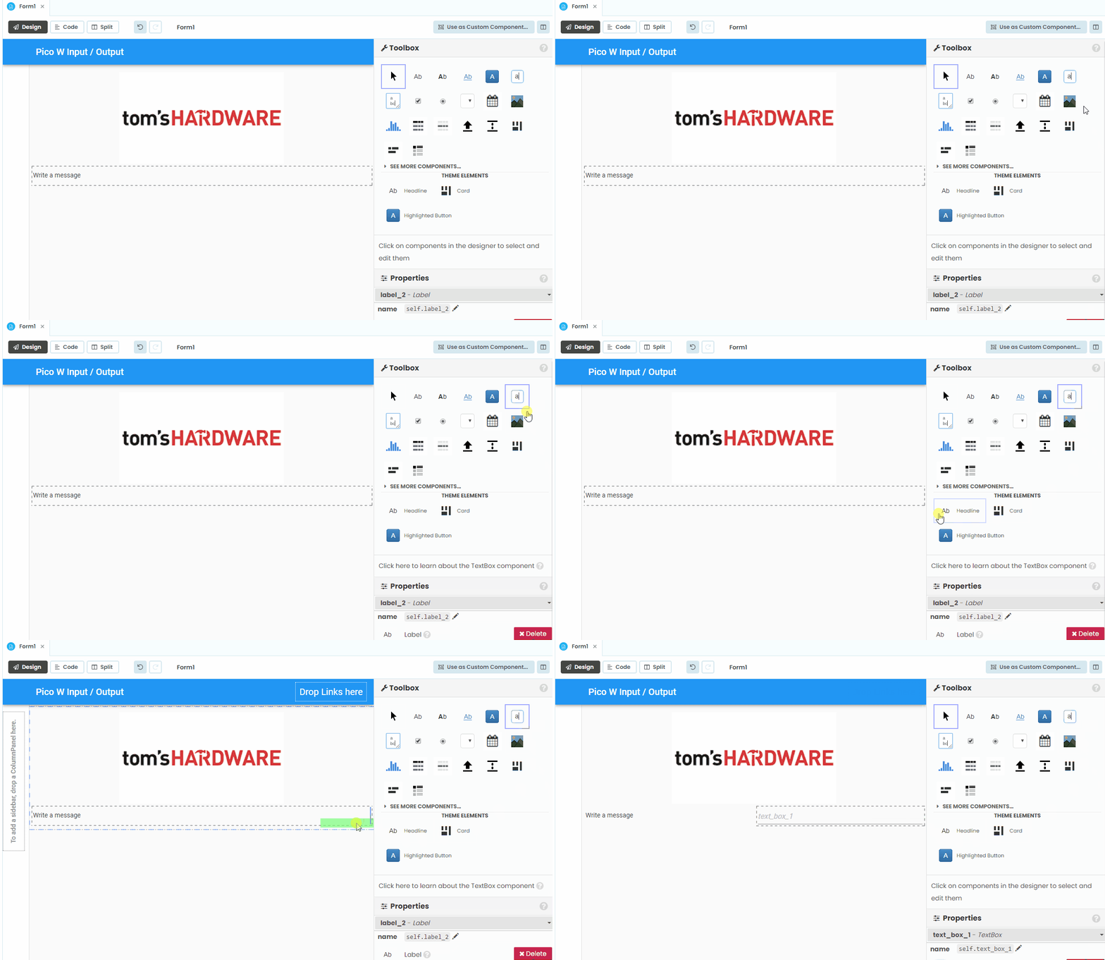
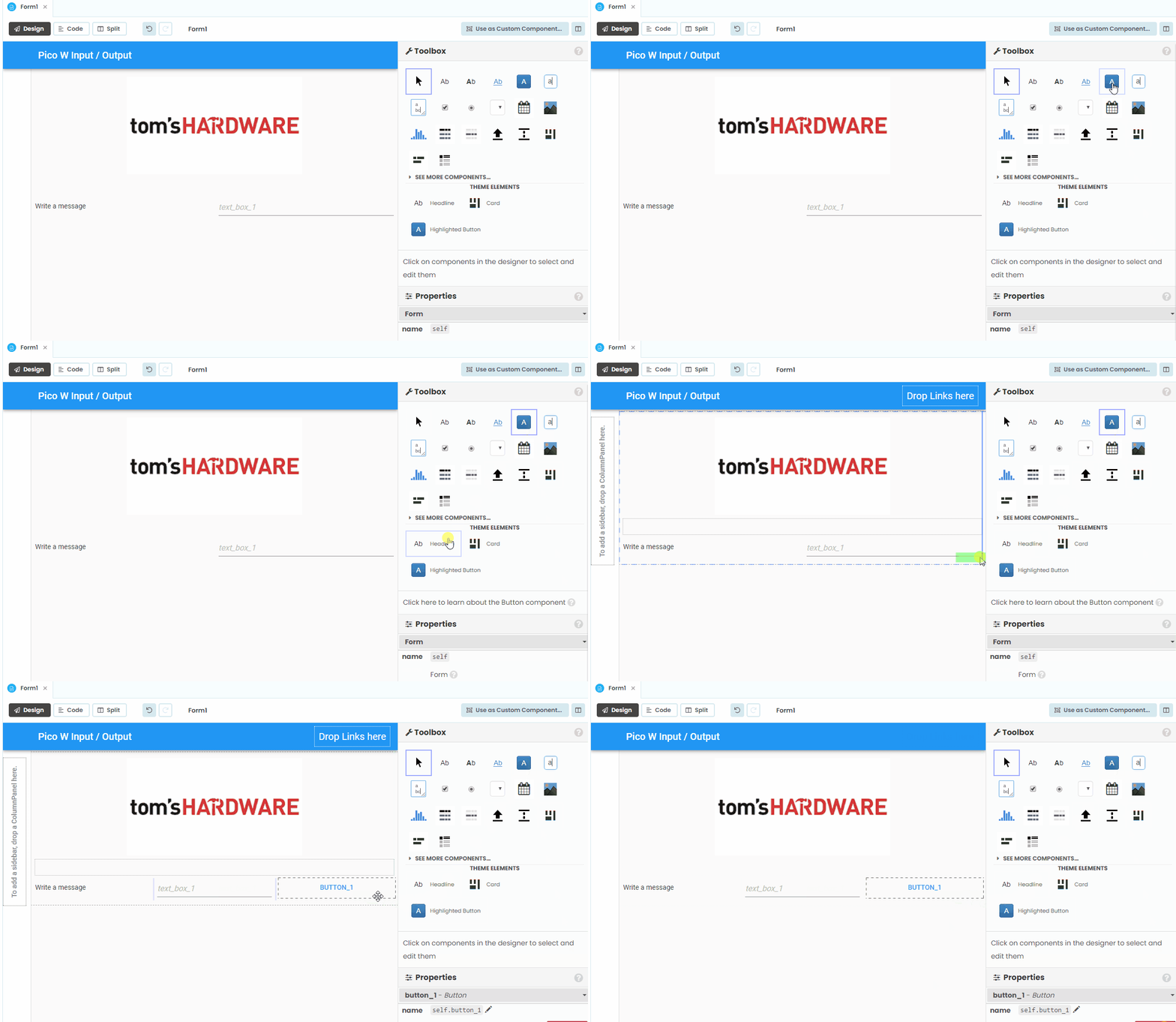
7. From the Toolbox, drag a text box and place it to the right of the “Write a message” label. Anvil will adjust the layout to accommodate the text box.
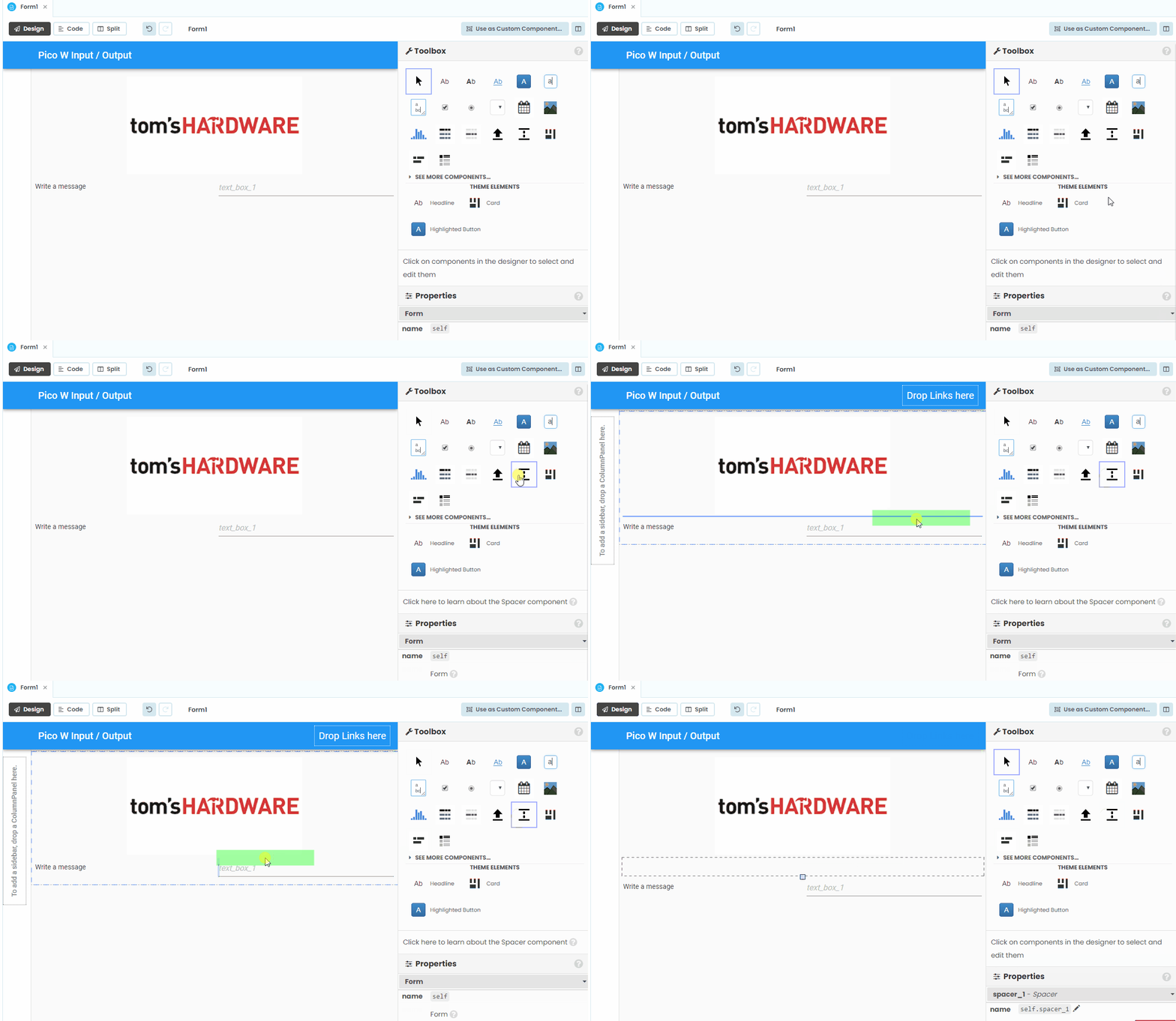
8. From the Toolbox, drag a space and place below the image, and above the label and text box. This spacer is used to add a little distance between the image and the app.
9. From the Toolbox, drag a button and place it next to the text box. This button will be used to “send” a message to the Raspberry Pi Pico W.
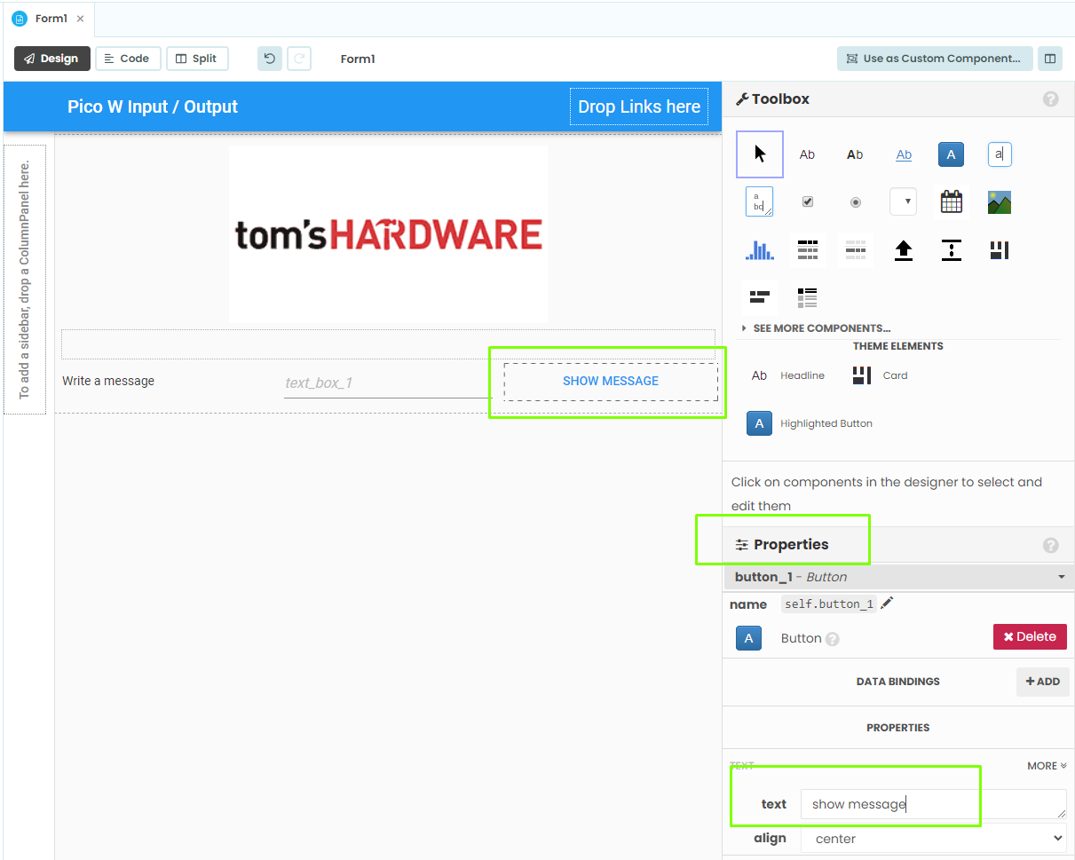
10. Change the button text via the Properties section. A simple “Show Message” is all we need as this button will trigger a function to send a message to the Pico W’s LCD screen.
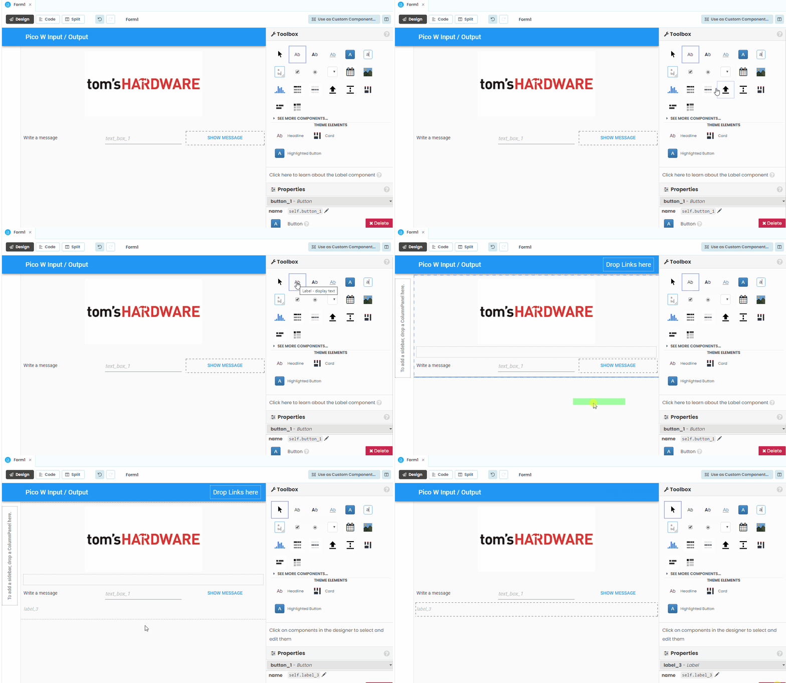
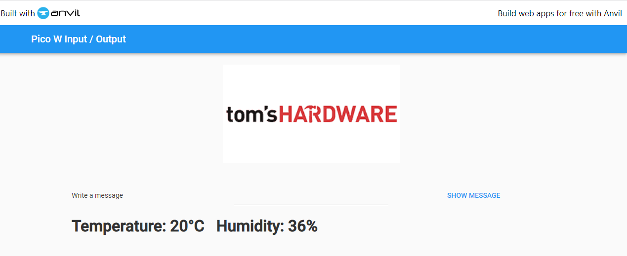
11. Drag another label and place it under the previous elements. This label will show the DHT11 sensor data from the Pico W.
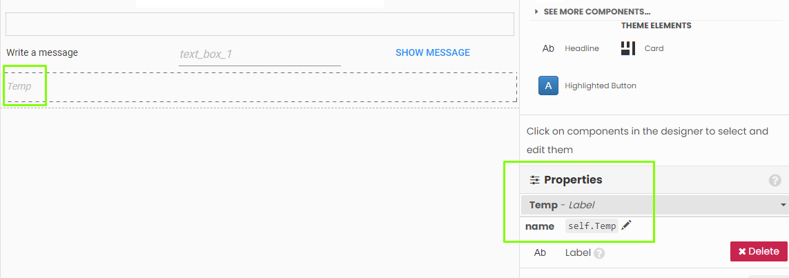
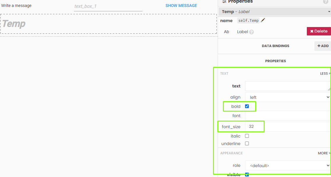
12. Change the name of the label to Temp. Anvil will auto insert “self.”. This will enable us to identify the correct label in Code, which will display our sensor data.
13. In Properties, scroll down to Text and click MORE. Then set the text to bold, and font size to 32pt.
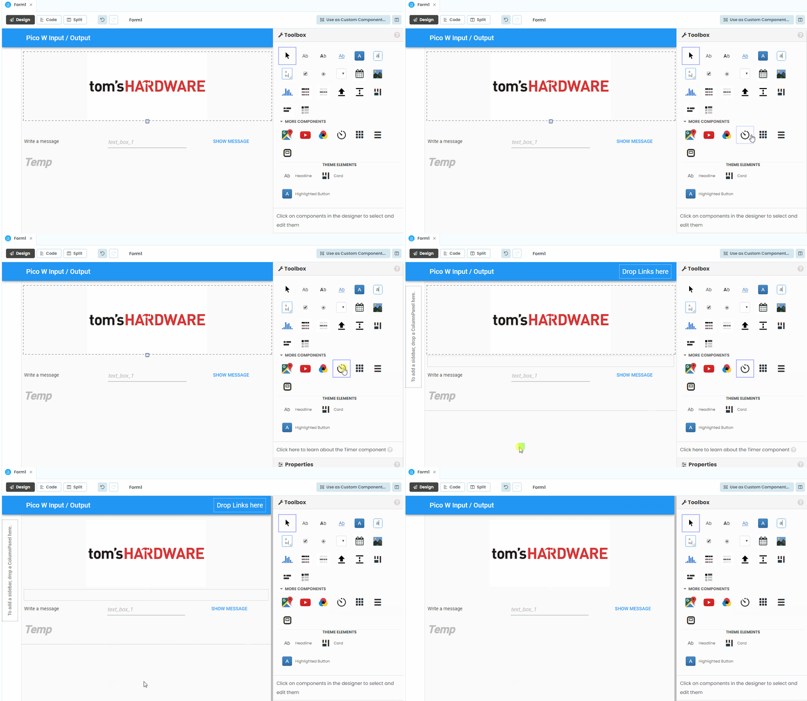
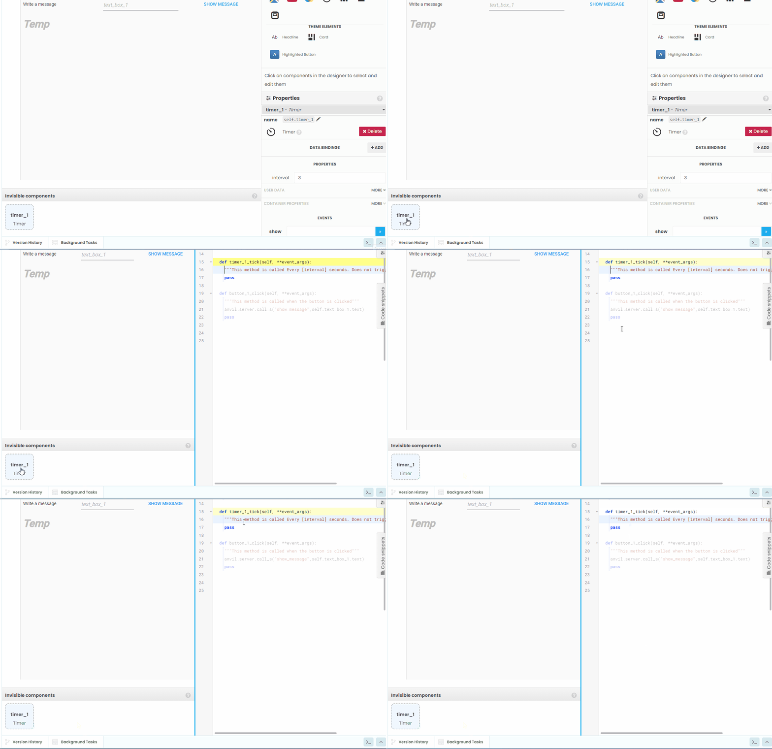
14. In the Toolbox, click on More Components and drag the Timer into the form.
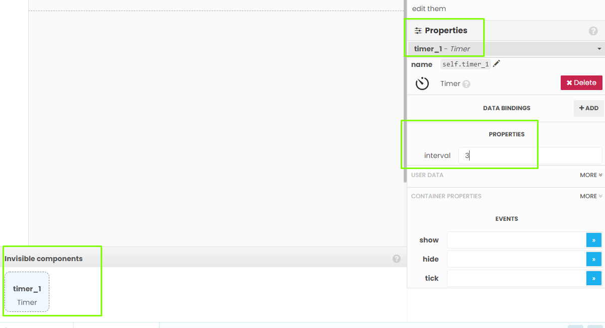
15. Using the Properties, set the timer to an interval of 3 seconds. This time is used to update the screen for our sensor data.
With the design now complete, our focus turns to the Code section which will bring the functionality to the project.
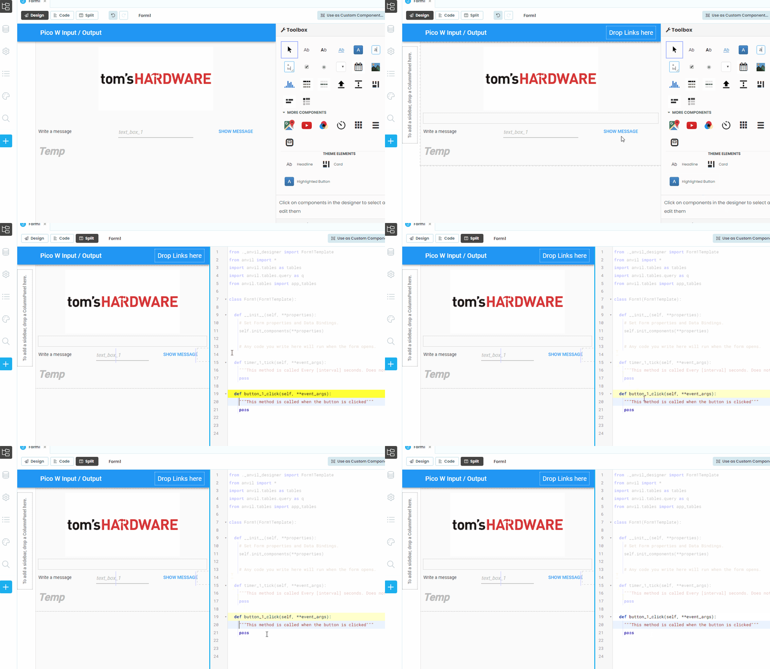
1. Double click on the SHOW MESSAGE button to open a split view code editor. The code which relates to the button is automatically highlighted.
2. Add a new line to the function which will call the “show message” function that we created on the Raspberry Pi Pico W. The function on the Pico W requires a message to be sent, and we get this by using the text from the text box. The anvil.server_call_s call will run the command, but we will see no output in the web app.
anvil.server.call_s("show_message",self.text_box_1.text)3. Double click on the Timer element to edit its code.
4. Add two lines to the timer function. The first to create a variable, data, which will store the data sent using the “dht11data” function on the Pico W. The second sets the Temp label text to show the message from the Pico W.
   data = anvil.server.call_s("dht11data")
self.Temp.text = dataLinking Raspberry Pi Pico W to Anvil
Anvil has an “uplink” tool, which enables the Raspberry Pi Pico W (and the Raspberry Pi) to securely connect to Anvil’s servers and communicate between the Pico W and the web app.
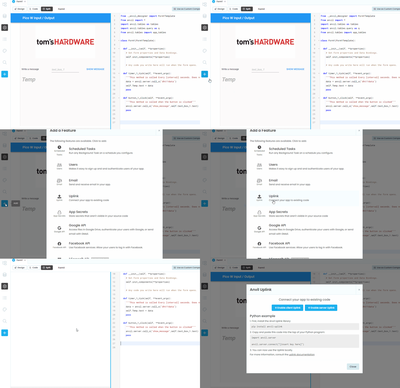
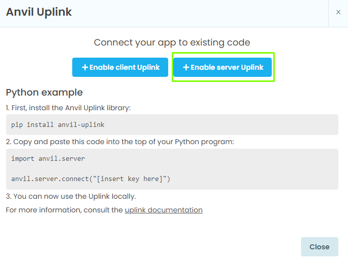
1. On the left of the screen, click on the blue + and from the menu select Uplink.
2. Click on Enable server Uplink.
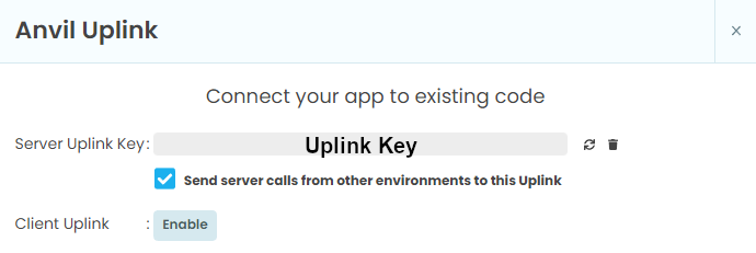
3. Copy the uplink key. Do not share this key with anyone else.
4. Open main.py in Thonny and paste in the Uplink key to the UPLINK_KEY variable. Click Save.
Running the Web Application
With both sides of the project complete, now we use Anvil’s Uplink to communicate between the Raspberry Pi Pico W and Anvil’s servers.
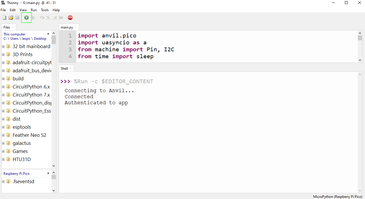
1. In Thonny, click on Run to start the code. It will take the Raspberry Pi Pico W a few moments to connect to the Wi-Fi, confirmation of which can be seen in the Python shell.
2. Go back to Anvil and click on Run to start the web app.
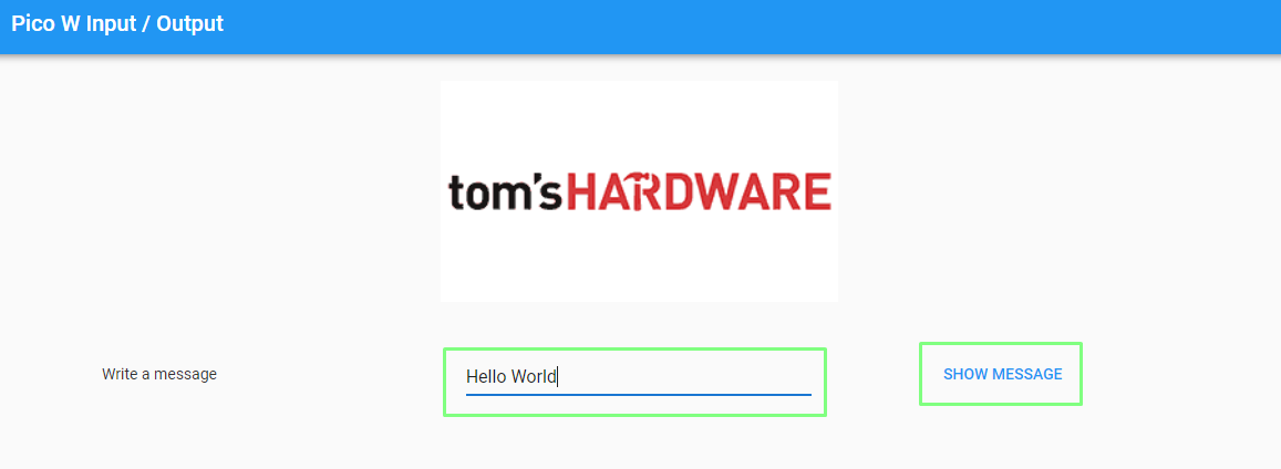
3. Type in a message, and click SHOW MESSAGE to send it to the Pico W. The LCD display will flash three times and then display the message. The current temperature and humidity will appear in the app.
Publishing the Application
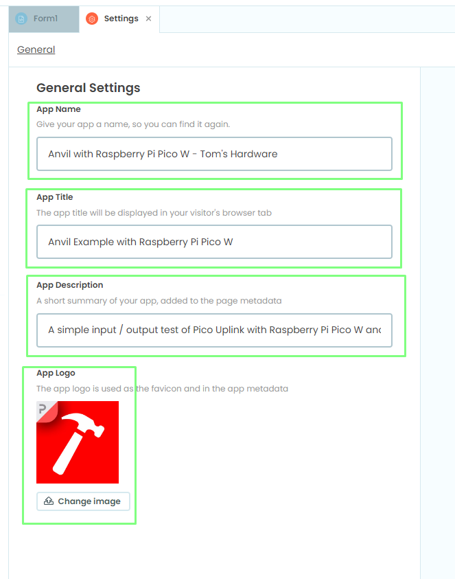
Currently the application is only available to us. We can easily share the application by publishing it. But first we need to give our app a name, title, description and logo.
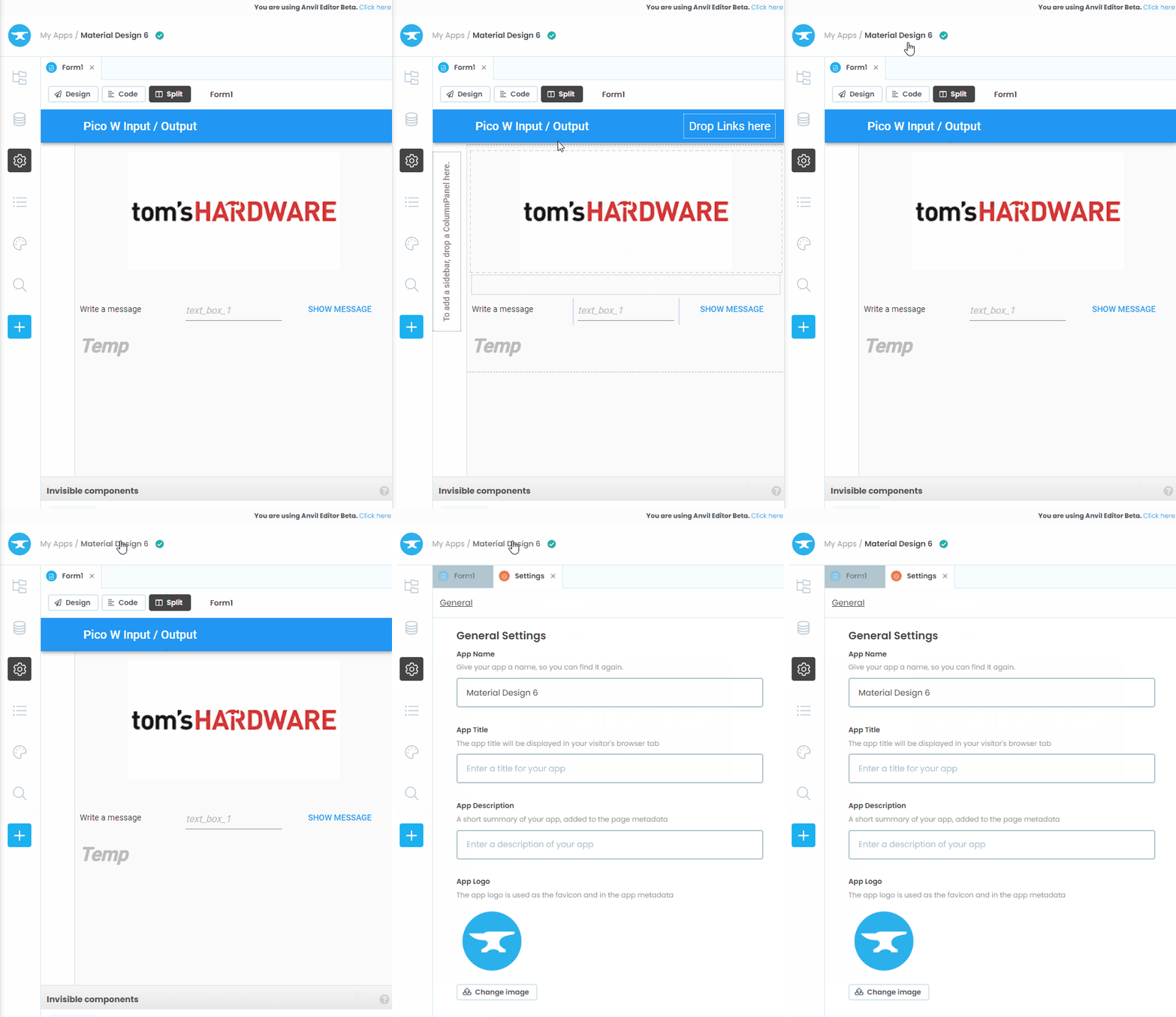
1. Click on My Apps / Material Design to open the Settings tab.
2. Give the application a name, title, description, and add an icon.
3. Click Publish.
4. Click Add Private URL and copy the URL. This URL is useful for sharing with friends and colleagues when testing the app.
5. Click the link to ensure that everything is working. Note that you will need to start the code on the Raspberry Pi Pico W.
6. Click Add Public link to create a public app.his link is easier to read . A public link can be used when you are ready to share the project on social media.
7. Click the link to test that it works. The code on the Raspberry Pi Pico W must also be running.
We now have a working web application running via a Raspberry Pi Pico W and Anvil’s servers.

Les Pounder is an associate editor at Tom's Hardware. He is a creative technologist and for seven years has created projects to educate and inspire minds both young and old. He has worked with the Raspberry Pi Foundation to write and deliver their teacher training program "Picademy".
-
vtt-info The wonderful example is now running with me.Reply
How can I now install a watchdog?
If the Pico W gets stuck.
