How to Use Your Raspberry Pi Pico With DC Motors
Make things move with your Raspberry Pi Pico and a DC motor.

The Raspberry Pi Pico is an enticingly small, yet powerful board that offers users the chance to create projects both great and small. One type of project is robotics and for this we need motors. So how can we control DC motors with a Raspberry Pi Pico? Can we connect them directly to the GPIO? The short answer is no.
The GPIO pins of the Raspberry Pi Pico cannot deliver the current needed for a DC motor and, if we were to try, there is a good chance that we would damage the Pico. Instead we need a motor controller that acts as a bridge between the Pico and our motor. We turn two Pico GPIO pins on / off and they control the motor controller which will in turn, turn on / off two outputs to make the motor move.
For this project you will need
- Raspberry Pi Pico running MicroPython (see how to set up Raspberry Pi Pico)
- Thonny installed on your computer
- 4 x Male to male jumper wires
- Half or full-size breadboard
- Motor controller board. In our case, we used a DRV8833 chip, but L298 or L9110S chips should also work.
- 5V / 6V DC Motor. We used a micro gear metal motor, but a standard DC hobby motor will also work. Note that the motor will need 2 x male to male jumper wires to connect to the breadboard.
Hardware Setup of DC Motor with Raspberry Pi Pico
The chip we are using in this project is a DRV8833 and our particular version is made for breadboards, but there are many other versions including a version designed for embedding in robots. There are also other motor controllers on the market, such as the L298D and L9110S which are simple and affordable components for robotics. All motor controllers share the same input/output conventions.
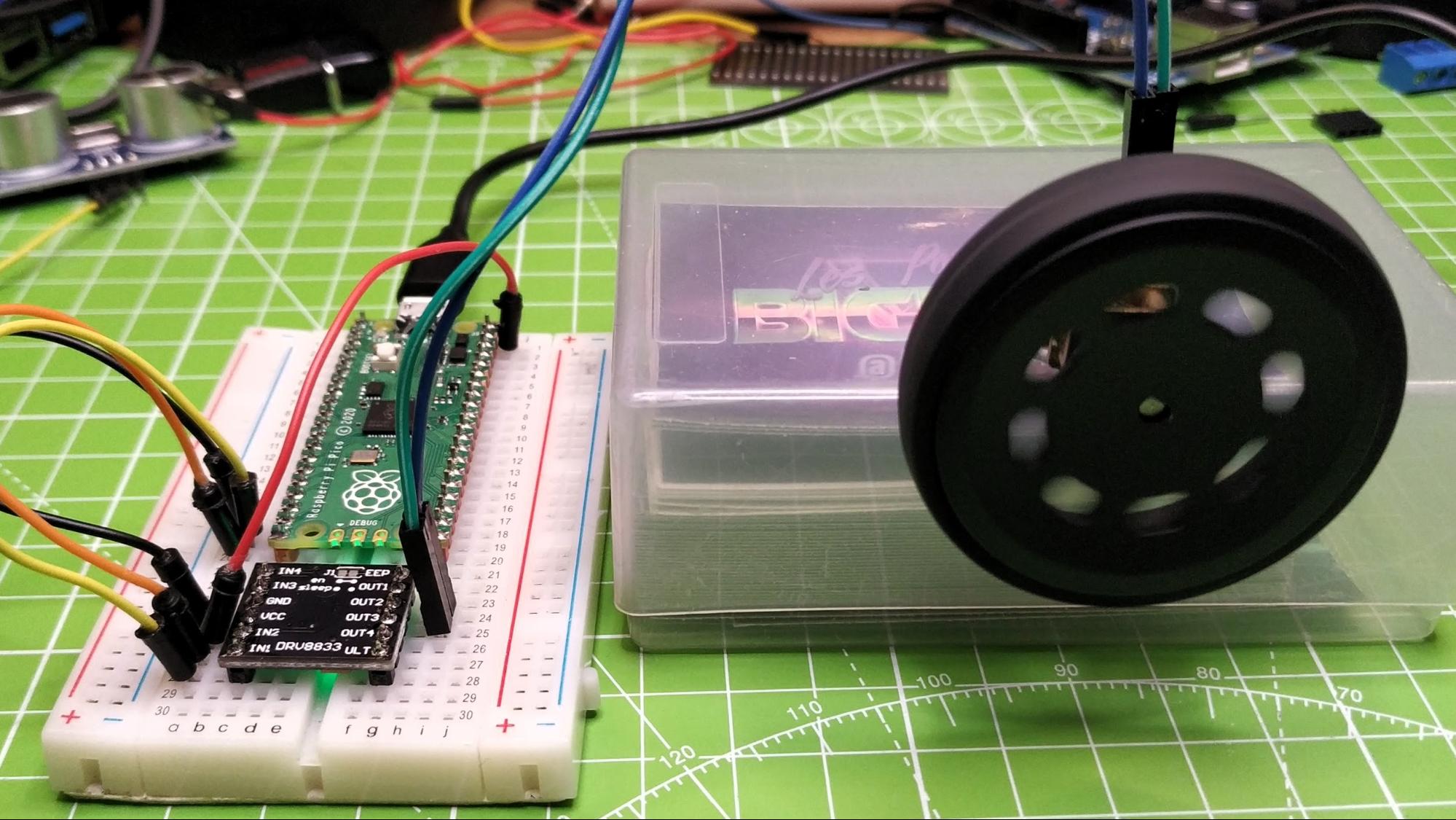
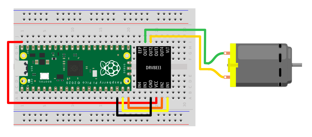
- Place the Raspberry Pi Pico into the breadboard so that the micro USB port hangs over the end of the breadboard.
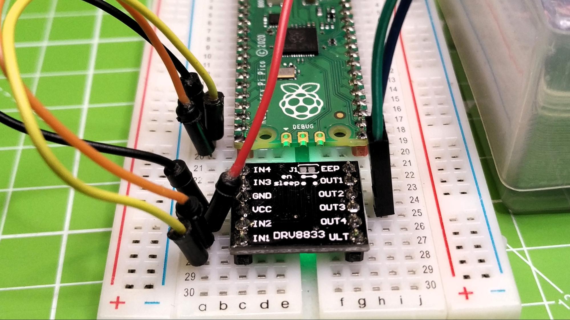
- Place the DRV8833 motor controller into the breadboard so that the pins are either side of the central channel.
- Connect the VBUS pin of the Raspberry Pi Pico to the VCC pin of the DRV8833 using a jumper wire. This will power the motor controller directly from the 5V supplied via USB.
- Connect the Raspberry Pi Pico GND pin to the GND pin of the DRV8833.
- Connect GPIO 14 of the Raspberry Pi Pico to IN1 of the DRV8833.
- Connect GPIO 15 of the Raspberry Pi Pico to IN2 of the DRV8833.
- Connect OUT1 and OUT2 to the pins of the motor, it doesn’t matter which for this test.
Software Setup of DC Motor with Raspberry Pi Pico
With the circuit built, connect your Raspberry Pi Pico and open the Thonny application.
import utime
from machine import Pin
2. Create two objects, motor1a and motor1b. These will store the GPIO pin numbers used as outputs to control the DRV8833 motor controller.
motor1a = Pin(14, Pin.OUT)
motor1b = Pin(15, Pin.OUT)
3. Create a function to move the motor “forward”. To do this we need to tell one pin to pull high, the other low. This, in turn, communicates our intended direction to the motor controller and the corresponding output pins will follow suit forcing the motor to move in a set direction.
def forward():
   motor1a.high()
   motor1b.low()
4. Create a function to move “backward.” This sees the GPIO pin states reverse, causing the motor to spin in the opposite direction.
Get Tom's Hardware's best news and in-depth reviews, straight to your inbox.
def backward():
   motor1a.low()
   motor1b.high()
5. Create a function to stop the motor. By pulling both pins low, we tell the motor controller to stop all movement of the motor.
def stop():
   motor1a.low()
   motor1b.low()
6. Create a final “test” function that will call the previous functions and run a test sequence that will spin the motor “forward” for two seconds, then “backward” for two seconds. It then stops the motor.
def test():
   forward()
   utime.sleep(2)
   backward()
   utime.sleep(2)
   stop()
7. Create a for loop which will run the test function five times.
for i in range(5):
test()
Save the code to the Raspberry Pi Pico as motor.py and click on the green arrow to run the code. The motor will rotate in both directions five times.

Les Pounder is an associate editor at Tom's Hardware. He is a creative technologist and for seven years has created projects to educate and inspire minds both young and old. He has worked with the Raspberry Pi Foundation to write and deliver their teacher training program "Picademy".
-
CooliPi Using PWM or Delta-Sigma modulation, it's possible to regulate torque of the motor (it's proportional to the current).Reply
I used it once with L298.
Using hardware PWM or those bitbanging GPIO processors, it should be possible to make it analogue and very precise using delta-sigma modulation with the latter. -
Bobber76 Hello, first I am relatively new to micro controllers / micropython so apologies in advance if I'm asking the obvious.Reply
I tried to replicate this demo and I've had partial success. The programs starts and the motor begins to move. Almost immediately after the motor initiates movement the programs stops and gives me the following error.
Connection lost (read failed: device reports readiness to read but returned no data (device disconnected or multiple access on port?))
Now I soldered the DRV8833 board myself and it was my first time soldering. Could I have a bridge between 2 pins? (Multiple access on port?)
I took a couple of pictures of the soldering. Maybe something is obvious to you guys more experienced There are a couple of pins where I wonder if I have contact but I don't recognize any bridging. Unfortunately I can't seem to figure out how to attach a local image to this message. :(
My code is as follows...
import utime
from machine import Pin
motor1a = Pin(14, Pin.OUT)
motor1b = Pin(15, Pin.OUT)
def forward():
motor1a.high()
motor1b.low()
def backward():
motor1a.low()
motor1b.high()
def stop():
motor1a.low()
motor1b.low()
def test():
forward()
utime.sleep(2)
backward()
utime.sleep(2)
stop()
for i in range(5):
test()
print("test number", i+1)
Any suggestions would be greatly appreciated,
Bob -
Bobber76 Still struggling with this almost a week later. Thusfar I have...Reply
Soldered a new DRV8833 chip. Confirmed continuity with a multimeter
Substituted a new breadboard
substituted a new motor, confirmed correct contact
copy and pasted exact code from demo to eliminate typos
I'm really at a loss for what to look for next. Exact parts used assembly are
KOOBOOK DRV8833 Motor drive
and
Flormoon DC Motor
The code is listed above and I'm still getting the same error / behavior. The motor will turn for ~ ½ sec and then Thonny produces the following message,
Connection lost (read failed: device reports readiness to read but returned no data (device disconnected or multiple access on port?))
Any suggestions would be greatly appreciated.
Thanks, -
chabes @Bobber76 Have you tried powering the motors with a separate power supply, instead of the Pico's VBUS?Reply -
Bobber76 @chabes Yes, just received a AAx4 battery back from Amazon today and it did work. I'm fairly new to this so I wasn't quite sure how to connect everything on the breadboard. Black / negative from the battery pack was connected to ground and I connected red / positive to the VCC of the of the DRV8833 drive. That worked. All other connections were as described in the tutorial.Reply
Any idea why the demo was able to be powered from the pico but I needed the external supply?
Thank you for the reply... much appreciated. -
chabes @Bobber76 Sounds like you wired it correctly. I'm no expert, but I've run in to similar issues before with various other MCUs.Reply
I have a few USB cables that kinda suck (especially the longer ones), and they have been the source of some of my issues in the past. Could be something similar going on for you.
If not the cable, maybe the specific motor you have might be more power hungry than the OP's motor.
Someone more experienced than myself could probably provide a more thorough response.
Glad to hear you got it to work!


