How To Control Neopixels with BASIC on Raspberry Pi Pico
Go back to the 1980s for a new way to program your Raspberry Pi Pico
Get Tom's Hardware's best news and in-depth reviews, straight to your inbox.
You are now subscribed
Your newsletter sign-up was successful
In the 1980s, the boom in home computers saw machines from Atari, Apple, Commodore, Acorn, Sinclair et al all looking to introduce computing to a generation. In an example of history repeating itself we saw the emergence of the Raspberry Pi in the 2010s. But as Raspberry Pi and Python now go hand-in-hand for this generation, in the 1980s it was BASIC.
BASIC, Beginners All-Purpose Symbolic Instruction Code is a high level, human readable language originally developed in 1964 by John G. Kemeny, Thomas E. Kurtz and Mary Kenneth Keller at Dartmouth College. BASIC came to prominence in the late 1970s, thanks to the rise of home computers. The 1980s saw BASIC, multiple versions of the language, for many different home computers. Microsoft BASIC, TI-BASIC, Amiga BASIC, AppleSoft BASIC. BASIC was both our programming language and a means to control our home computers.
Over time, BASIC faded into the shadows for many. Newer languages appeared and took over. Now we have thousands of programming languages to choose from. When it comes to the Raspberry Pi Pico our choice is a little more limited, but now we can add one more to the list.
PicoMite is the name of a Raspberry Pi Pico based project that sees a version of BASIC (MMBASIC in this case) used to control the GPIO of the Pico. The “Mite” term comes from the creator, Geoff Graham’s range of Maximite and Micromite boards which use Arm based SoCs to power powerful home computers which run a flavor of BASIC.
PicoMite is a more “lightweight” product, designed for the $4 Raspberry Pi Pico, enabling BASIC code to control and work with GPIO pins, sensors, RGB LEDs and other components. In this how to, we shall create our own PicoMite device and use it to control a series of Neopixel RGB LEDs.
For this project you will need
- Raspberry Pi Pico
- Half-sized breadboard
- LED
- 220 Ohm resistor (Red, Red, Brown, Gold)
- 2x Male to male jumper wires
- Neopixel strip
Setting up PicoMite
1. Navigate to the PicoMite webpage and scroll down to the Downloads section. Download the latest PicoMite firmware.
2. Extract the contents of the download.
Get Tom's Hardware's best news and in-depth reviews, straight to your inbox.
3. Press and hold the BOOTSEL button of the Raspberry Pi Pico and connect via USB to your computer. A new drive, RPI-RP2 will appear, this is our Raspberry Pi Pico.
4. Copy the PicoMite UF2 firmware file to the RPI-RP2 drive. After a few moments the drive will disappear and our Pico is now running the Pico version of MMBASIC.
Connecting to PicoMite
In order to use PicoMite, we need to create a serial connection between our computer and the Raspberry Pi Pico. The best tool for the job on Windows is PuTTY.
1. Download and install PuTTY to your Windows machine.
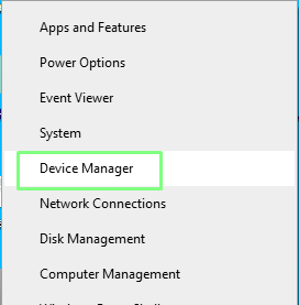
2. Right click on the Windows menu and select Device Manager.
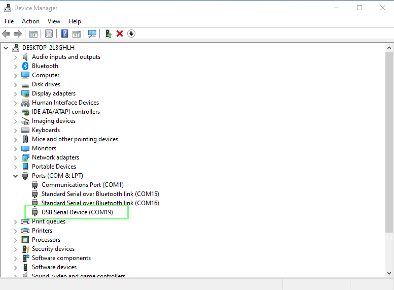
3. Scroll down to Ports (COM & LPT) and click on the drop down arrow. Make a note of the USB Serial Device COM port.
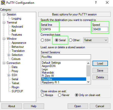
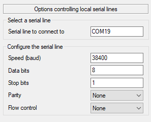
4. Open PuTTY and click on Serial. Enter the COM port for your PicoMite and set the speed to 38400.
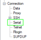
5. From the Category menu (left) click on Serial.
6. Set your serial configuration as follows. Speed 38400, Data bits 8, Stop bits 1, Parity None, Flow Control None.
7. From the Category menu, click on Keyboard and set the Backspace key to Control-H. This will enable us to use the backspace key to delete any errors in our code. If this setting is not enabled, the backspace key is deactivated.
8. Click on Session, name your session PicoMite and click Save. We now have the settings ready to go whenever we wish to use PicoMite with PuTTY.
9. Click on Open to create a connection.
Using PicoMite with MMBASIC
The first thing we see with MMBASIC is nothing. A blank screen with a prompt is all that greets. But from here we can write BASIC code, line by line, which runs each time we press the Enter key.
Lets use a quick print command to test that everything is working as expected. Press Enter at the end of the line to run the code, you should see the message appear on screen.
print “Hello World”We need to create a file to do more with the code.
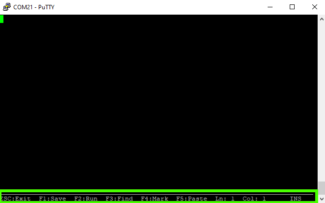
1. Type edit and press Enter. This opens a basic text editor and at the bottom of the screen we can see that the function keys are used to Save, Run, Find, Mark (highlight for cut/copy) and Paste.
2. Create a comment, starting with ‘, that will identify what the project will do. Comments, remarks in BASIC parlance, are ways to leave messages in our code. For MMBASIC they also double as project filenames.
‘For loop3. Create a for loop that will iterate ten times.
For i = 1 To 104. Inside the for loop, add a print command to print a message to the screen.
Print “Tom’s Hardware”5. Close the for loop using Next. This will increase the value of i each time the loop iterates. When it hits 10, the loop ends.
Next i6. Press F1 to save. This will also exit us from the editor.
7. Save the code to slot one of the onboard memory. PicoMite has seven slots into which we can save code.
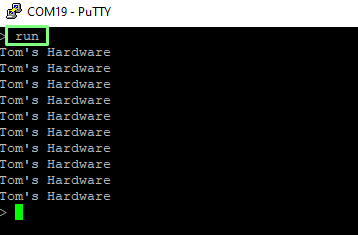
flash save 18. Type run and press Enter to start the code. A message will appear ten times.
For Loop Complete Code Listing
'For Loop
For i = 1 To 10
Print "Tom's Hardware"
Next i
Using the GPIO
As this is a Raspberry Pi Pico, we can do much more than print strings of text. MMBASIC has access to the GPIO. We have digital, analog, PWM, I2C, SPI, RS232 and 1-Wire. Let's start simple with an LED.
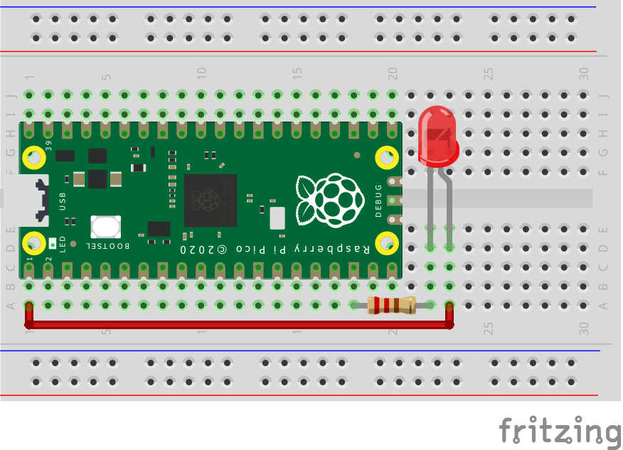
The LED has two connections, the anode and cathode. The Anode (long leg) connects to GP0 via a male to male jumper wire. The Cathode (short leg, GND) connects to any GND pin on the Pico via a 220 Ohm resistor.
1. Type edit and press Enter. This opens a basic text editor.
2. Name the project LED Blink.
‘LED Blink3. Set GPIO pin 0 as an output.
SetPin GP0, DOUT4. Create a variable, delay, into which we store the value 1000. This is a one second delay in milliseconds.
delay = 10005. Create a label, Blink_Loop: which indicates the start of our looped code. BASIC can use labels or line numbers, going up in steps of 10, to indicate positions in code.
6. Turn the LED connected to GP0 on, and use a print command to write “On” to the screen. By printing a message to the screen we can see that the loop is working, should our LED circuit be incorrect.
Pin(GP0) = 1
Print “On”
7. Add a pause, using the value stored in delay. This will keep the LED lit for one second.
Pause delay8. Turn the LED off, print off to the screen and then pause for one second.
Pin(GP0) = 0
Print "Off"
Pause delay
9. Use a GoTo command to send the code back to Blink_Loop, closing the loop.
GoTo Blink_Loop10. Press F1 to save and exit the code.
11. Save the project to slot two of the onboard memory.
flash save 212. Type run and press Enter to start the code. The LED should now blink every one second. Press CTRL+C to exit the code.
LED Blink Complete Code Listing
'LED Blink
SetPin GP0, DOUT
delay = 1000
Blink_Loop:
Pin(GP0) = 1
Print "On"
Pause delay
Pin(GP0) = 0
Print "Off"
Pause delay
GoTo Blink_Loop
Loading Code
We now have two projects saved to PicoMite but only one can run at once.
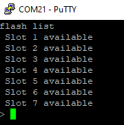
1. List the projects saved to the PicoMite.
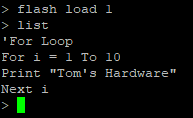
flash list2. Load the for loop code from slot one.
flash load 13. List the contents of the code, type list and press Enter.
4. Type run and press Enter to run the code.
What if we want to run our code when the Raspberry Pi Pico is away from a computer? Let's say that we want the LED blink project to load when the PicoMite is powered up.
Use this command to set the LED Blink code in slot 2 to load on boot.
option autorun 2Controlling NeoPixels with PicoMite
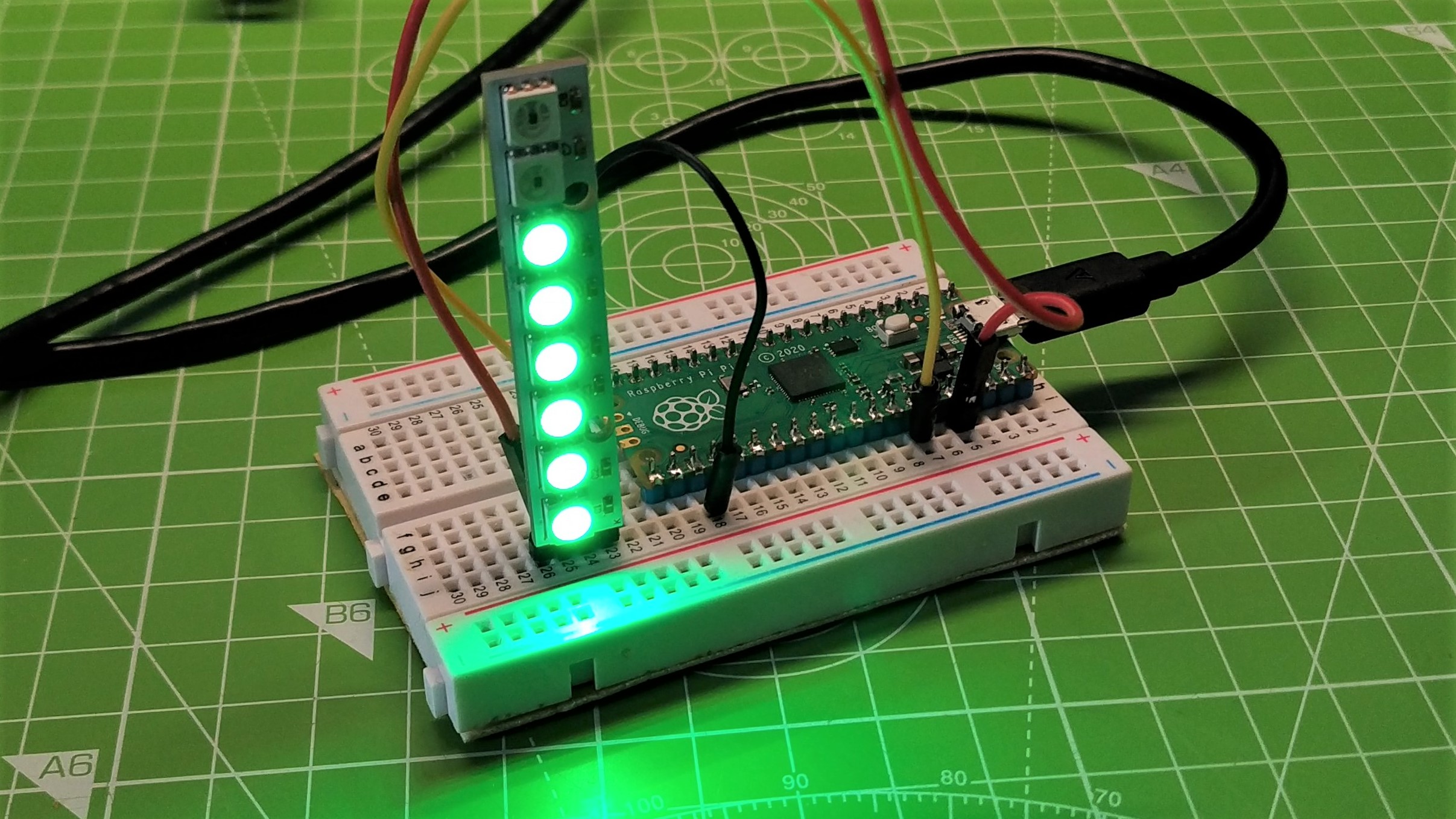
You read that right! Normally we need CircuitPython, MicroPython or C to control NeoPixels with the Raspberry Pi Pico. But PicoMite supports “bitbanging”, where we create the signals / pulses necessary to control WS2812 RGB LEDs in software.
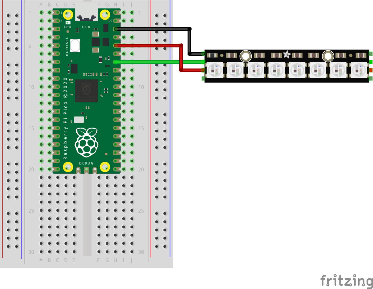
The circuit for NeoPixels is simple. We have three connections.
| Raspberry Pi Pico | NeoPixel | Wire Color |
|---|---|---|
| 3v3 | VCC | Red |
| GND | GND | Black |
| GPIO28 | Data In (DIN) | Green |
The code for this project is a little more complicated as we shall be using arrays (groups of variables essentially) to control the color of each LED in a chain of six.
1. Load an empty slot for the code.
flash load 32. Open the slot using edit.
3. Add the comment ‘Neopixels. Remember this will be the title of the code in slot 3.
4. Create a variable called delay and in there store 1000. This will be a one second delay between each color in the cycle.
delay = 10005. Create an array (Python calls this a list) which will contain the six values for each of the six Neopixels that we wish to control. In BASIC we have to create the dimensions (size) of the list. The ! denotes that our array contains Integers, and each is an RGB value, in this case red.
Dim a%(5)=(RGB(red),RGB(red),RGB(red),RGB(red),RGB(red),RGB(red))6. Create another array, this time to set the LEDs to green.
Dim b%(5)=(RGB(green),RGB(green),RGB(green),RGB(green),RGB(green),RGB(green))7. Create a final array, this time to set the LEDs to blue.
Dim c%(5)=(RGB(blue),RGB(blue),RGB(blue),RGB(blue),RGB(blue),RGB(blue))8. Set GPIO 28 to an output.
SetPin GP28, DOUT9. Create a label that indicates the start of a loop.
pixel_loop:10. Use the Bitbang command to simulate the WS2812 timing necessary to set the LEDs red. The WS2812 option has two settings for Neopixels. O for standard, and B for the WS2812B version. If one doesn’t work, try the other.
Bitbang ws2812 o, GP28, 6, a%()11. Add a pause.We use the value stored in delay as the duration.
Pause delay12. Use another bitbang to set the LEDs green, then add another pause. We use the values from the b array to set each LED green.
Bitbang ws2812 o, GP28, 6, b%()
Pause delay
13. Set the LEDs blue with a final bitbang command and short pause.
Bitbang ws2812 o, GP28, 6, c%()
Pause delay
14. Finally close the loop, instructing the code to go back to the label.
GoTo pixel_loop15. Press F1 to save the code.
16. Overwrite the code in slot 3. This makes sure that our code is correctly saved.
flash overwrite 317. Type run to start the code. Press CTRL+C to stop at any time.
Neopixel Code Listing
Your code for this project should look something like this.
'Neopixels
delay = 1000
Dim a%(5)=(RGB(red),RGB(red),RGB(red),RGB(red),RGB(red),RGB(red))
Dim b%(5)=(RGB(green),RGB(green),RGB(green),RGB(green),RGB(green),RGB(green))
Dim c%(5)=(RGB(blue),RGB(blue),RGB(blue),RGB(blue),RGB(blue),RGB(blue))
SetPin GP28, DOUT
pixel_loop:
Bitbang ws2812 o, GP28, 6, a%()
Pause delay
Bitbang ws2812 o, GP28, 6, b%()
Pause delay
Bitbang ws2812 o, GP28, 6, c%()
Pause delay
GoTo pixel_loop

Les Pounder is an associate editor at Tom's Hardware. He is a creative technologist and for seven years has created projects to educate and inspire minds both young and old. He has worked with the Raspberry Pi Foundation to write and deliver their teacher training program "Picademy".
-
lazzakin Thank you! This got me up and running. Question though: where can I find info on more fine-grained control of a neopixel strip with PicoMite basic? (e.g. brightness, RGB values, position, etc.)Reply
UPDATE: I found I can lower the brightness simply by changing the amount of RGB as a tuple. For example: this produces a dim red pixel, the rest black:
Dim a%(5)=(RGB(10,0,0),RGB(black),RGB(black),RGB(black),RGB(black),RGB(black))
