How to Make a Raspberry Beret with Raspberry Pi Pico
The Raspberry Pi Pico is the first official microcontroller from the Raspberry Pi Foundation. Because of its small size, it doesn't use a full-blown OS which makes it an ideal candidate for wearable projects and cosplay effects. In this project, I'm using a Raspberry Pi Pico to power and control an RGB LED inside of a hat—specifically a raspberry beret.
The Pico uses 3.3V, so it doesn't take much to get operations off the ground. Your biggest concern when it comes to power is physical size. It also helps that the Pico is Python-friendly offering both MicroPython and Circuit Python as an option for programming your LED functions. However, users can also take advantage of C.
This project was developed for our Raspberry Pi-themed podcast known as The Pi Cast. While this guide explains how I created my hat, you can easily adapt it to other projects with a little customization. This guide should ultimately provide enough information to get you started with using LEDs in wearable Pico projects.
Gather Project Components for Raspberry Pi Beret
At a bare minimum, your project needs a Raspberry Pi Pico, an LED, a resistor, wires and something for power. If you want to go bigger, you can add more LEDs and maybe even more Picos.
To get started and start prototyping, you will need:
- 1 Raspberry Pi Pico
- 1 LED, preferably an RGB LED
- 330 Ohm Resistors. If you have an RGB LED, get one each for R, G and B.
- 1 Battery (3.7V 1S Lipo, USB cable)
- Wires
- Breadboard (optional)
- Beret (you can sew or buy)
- Raspberry Pi Logo (3D-printed from this model)
I recommend using a USB cable to power operations while testing your circuit build. A battery is useful to have on hand to make sure everything is working wirelessly. I’m using a 3.7V 1S Lipo but a 2x or 3x AA battery pack may work in its place. In the end, I recommend using a battery like mine for form factor and performance.
Plan Your Design for Raspberry Pi Beret
This is the most creative part of the process! You need to decide what you're going to put your LEDs into. While I'm creating an LED hat, you could also adapt this project into something like a prop or decoration.
Get Tom's Hardware's best news and in-depth reviews, straight to your inbox.
If you want to sew your own beret like mine, the pattern is nothing more than circles drawn to match the measurements of my own head with a 3-inch brim. There are plenty of beret tutorials online so I'll focus mainly on the Pico integration. You can buy a raspberry-colored beret from Amazon to make things a little easier.
There are ways to disperse the light from LEDs for cool effects. Placing an LED behind thin paper will diffuse the glow while fiber optic filaments will refine it into bright points. Consider different ways you can make the most out of your LED effect.
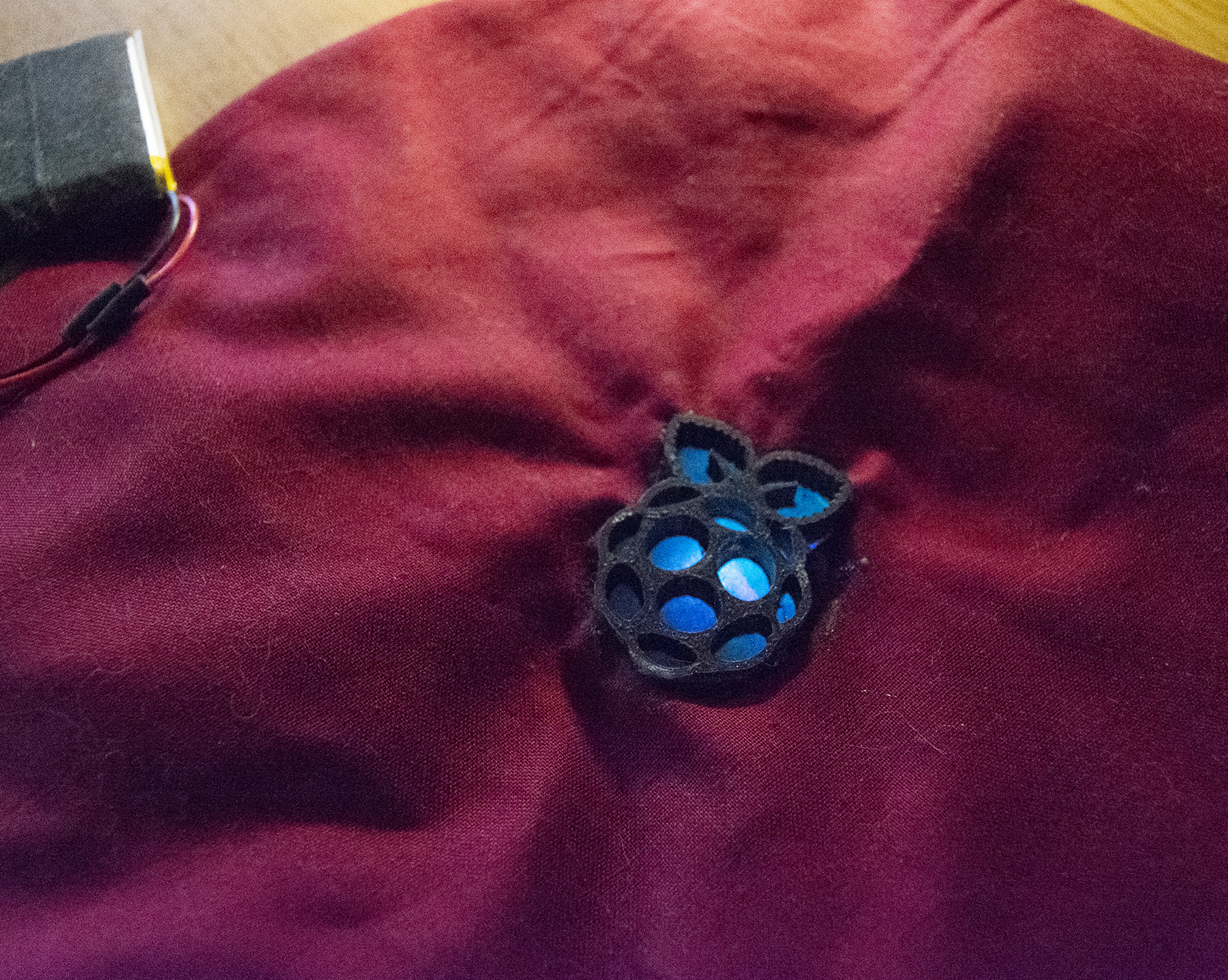
I'm 3D-printing a Raspberry Pi logo and backing it with pattern tracing paper to diffuse my RGB LED. You can download the file I used in this project from Thingiverse.
Prototype the LED Circuit for Raspberry Pi Beret
Before we go soldering our dream lightshow together, we need to prototype our design. This guide by our editor and resident Raspberry Pi guru, Les Pounder, walks you through setting up your Pico for the first time as well as controlling an LED. I'll assume you already know how to program the Pico and will focus on LED wiring. Please refer to Les's instructions for a more in-depth introduction to the Pico.
Your LED circuit will require a resistor, one per LED. The resistance value you need depends on the forward voltage of the LED you're using.
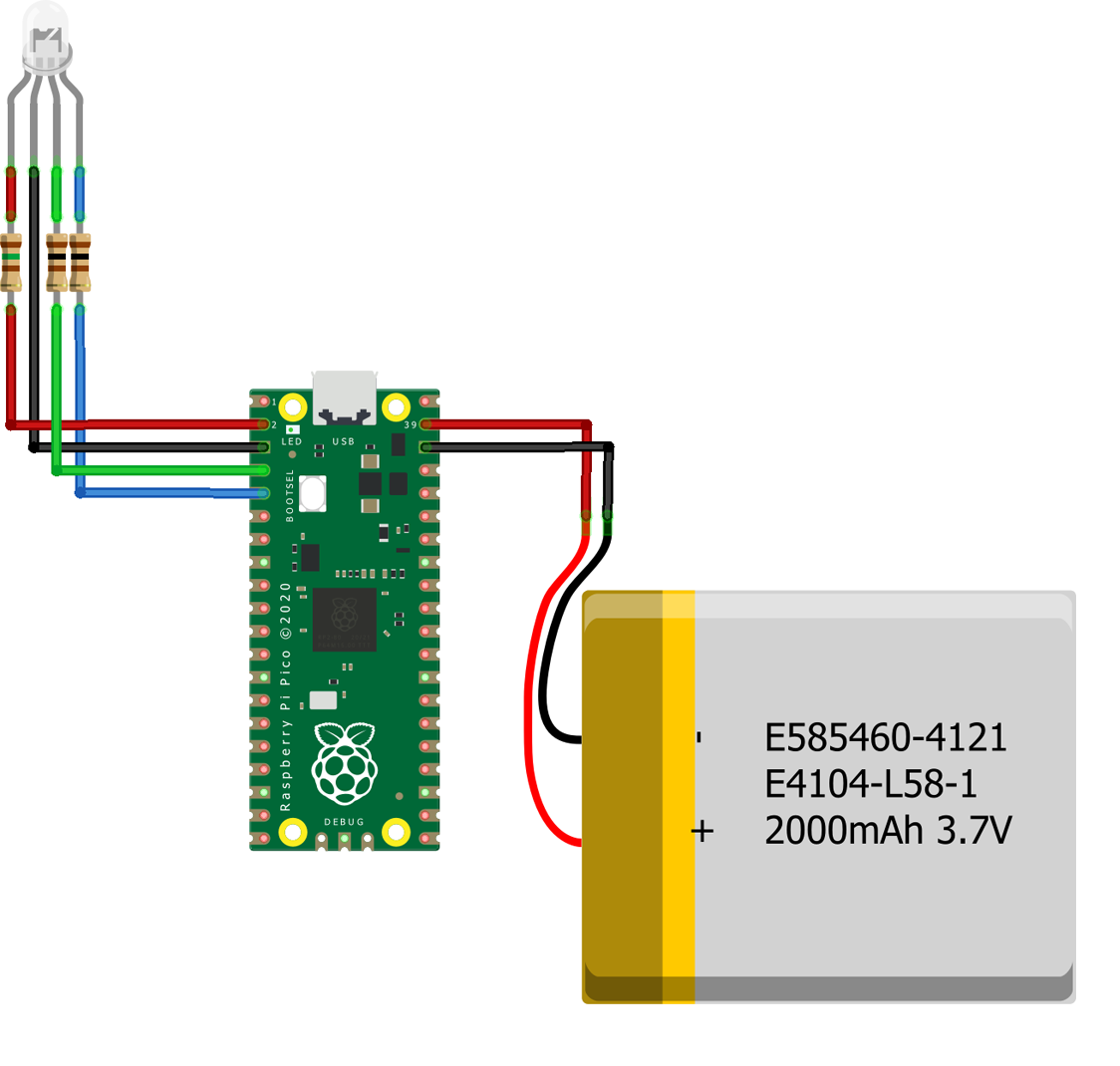
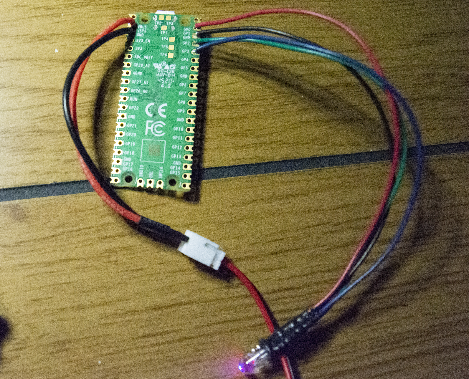
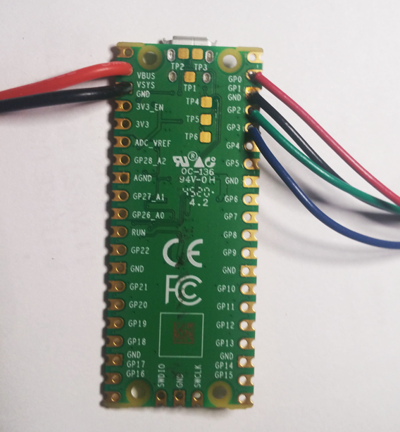
Here's a Fritzing diagram of the RGB LED configuration I'm using in the Raspberry Pi beret. The resistance requirements vary between each color of the LED, but a 330 ohm resistor will work for all of them (though some will be brighter than others). I'm using a common cathode LED, so each color shares the same ground. The LED is soldered to GPIO 1, Ground, GPIO 2 and GPIO 3. The 1s Lipo battery is powering the Pico using the VSYS and Ground points but it can also be powered using USB.
To build a test circuit, I recommend using a breadboard with jumper wires. This allows you to make changes in real time without commiting to a final design before it's ready.
Program Your LEDs
The LED circuit can be programmed using MicroPython, Circuit Python, or C. If you'd like to copy what I'm doing, here's a look at the MIcroPython code I'm using to make the RGB LED fade between different colors.
from machine import Pin, PWM
import math
import utime
blue = PWM(Pin(1))
red = PWM(Pin(2))
green = PWM(Pin(3))
blue.freq(1000)
red.freq(1000)
green.freq(1000)
def hsv_to_rgb(h, s, v):
   if s == 0.0: v*=255; return (v, v, v)
   i = int(h*6.) # XXX assume int() truncates!
   f = (h*6.)-i; p,q,t = int(255*(v*(1.-s))), int(255*(v*(1.-s*f))), int(255*(v*(1.-s*(1.-f)))); v*=255; i%=6
   if i == 0: return (v, t, p)
   if i == 1: return (q, v, p)
   if i == 2: return (p, v, t)
   if i == 3: return (p, q, v)
   if i == 4: return (t, p, v)
   if i == 5: return (v, p, q)
color_angle = 0
while True:
   color_angle += 1
   if color_angle > 360:
       color_angle = 0
   color_out = hsv_to_rgb(color_angle/360, 1, 1)
   red.duty_u16(int((color_out[0]/255)*1000))
   green.duty_u16(int((color_out[1]/255)*1000))
   blue.duty_u16(int((color_out[2]/255)*1000))
   utime.sleep(0.07)
This example uses modified code from Colorsys, an open-source Python library that isn't available for MicroPython. You can read more about the sample I'm using on Stack Overflow.
Powering Your Raspberry Pi Beret
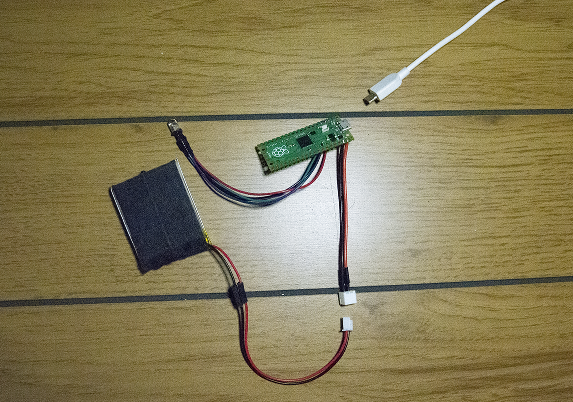
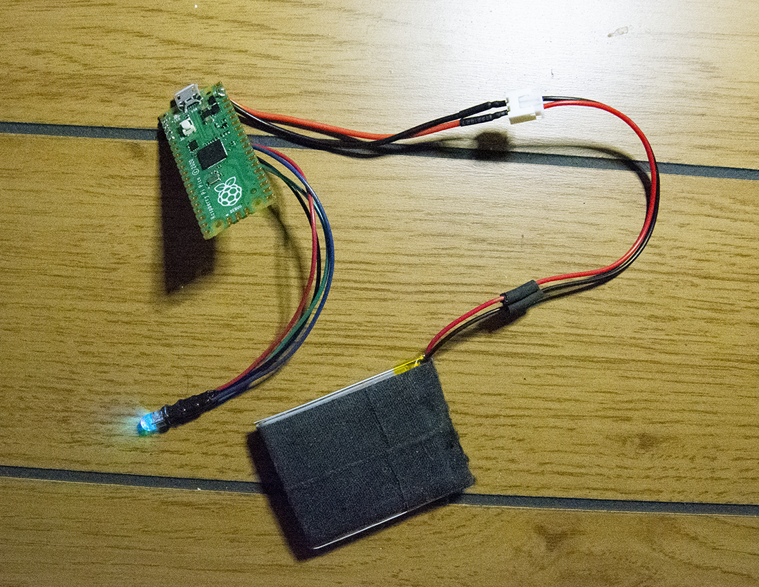
You can power your Pico via USB and use any portable battery to power the final project. To make things a little more compact, I'm using a small, 3.7V LiPo battery with a connector soldered to the VSYS and Ground points on the Pico. This allows the battery to be disconnected, exchanged or set aside for USB power.
Assembling the Hardware for Raspberry Pi Beret
Once you've determined what your circuit requires, how you're going to power it and what you're putting it inside of, it's time to begin assembly. Solder any permanent assets like battery connectors and LEDs into place on the Raspberry Pi Pico.
I recommend starting with the LEDs which can be tested with USB power as you go. I finished my project with heat shrink tubing. The resistors are soldered very close to the LED and wrapped in the black tubing for a clean finish.
Assemble Final Project
With your final LED circuit assembled, you can install the hardware in its new wearable case. This part involves creativity and at times persistence.
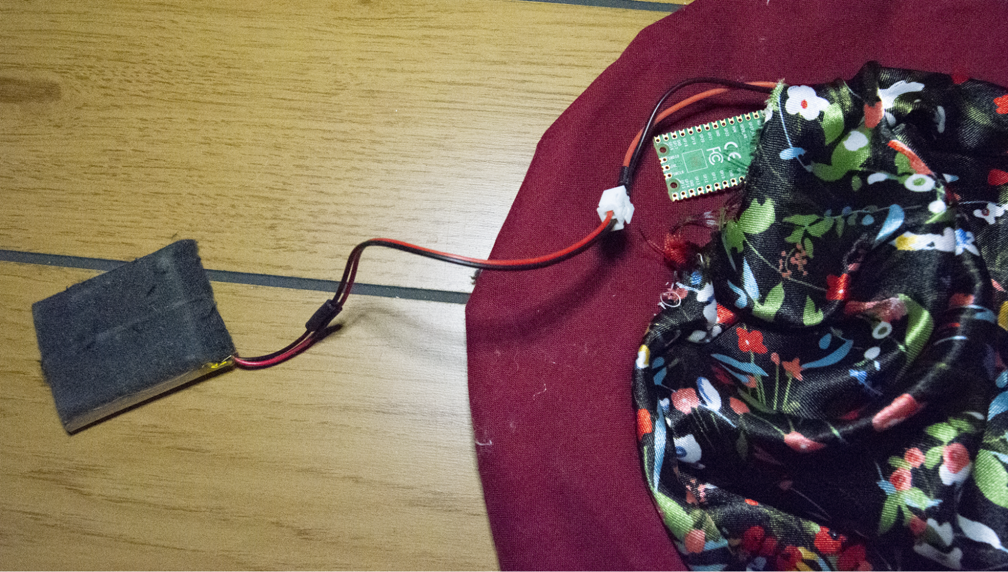
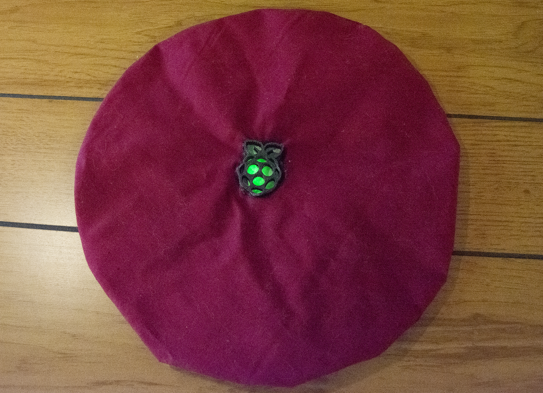
For my project, I cut a hole in the top center of the beret and glued the 3D-printed Raspberry Pi logo into place. The hat is lined with a gap between the outer and inner layer accessible through a small hole. The Pico, LED and battery can easily be put inside the hat and removed for maintenance. A small, removable pin is used to secure the LED behind the Pi logo but glue could be used to hold the LED into place permanently.
Show Off Your Hard Work
Once you've adapted your Pico-powered LED system into a wearable asset, it's time to show off your hard work! Share your creation with the community at large or maybe just a friend or two.
Upgrade Options
The best Raspberry Pi projects have room to grow. If this project left you itching for more, here are a few upgrade options that can take your Pico wearable to new heights.
Power Button - Adding a power button will save you precious seconds when turning your wearable project on and off. It also adds a professional touch.
Settings Button - If you want multiple lighting effects, a button could be used to change between them.
USB Rechargeable - For permanent projects, consider adapting your power system to be USB rechargeable. Adafruit has a few modules that can be used to accept USB input to recharge batteries.
Wi-Fi Support - Adding WiFi support to your Pico wearable is an option. Check out Les's guide on adding WiFi to the Pico. The LED could be programmed to respond to WiFi signals or remote commands.
No matter what sort of LED wearable you're trying to create, the Pico offers an affordable starting point with plenty of flexibility for both simple and complex projects. Upgrading is optional but the creative risks you take will ultimately make the final project your own.

Ash Hill is a contributing writer for Tom's Hardware with a wealth of experience in the hobby electronics, 3D printing and PCs. She manages the Pi projects of the month and much of our daily Raspberry Pi reporting while also finding the best coupons and deals on all tech.

