How to Use a Motion Sensor with Raspberry Pi Pico
Learn the basics of input and output by setting up a motion sensor.
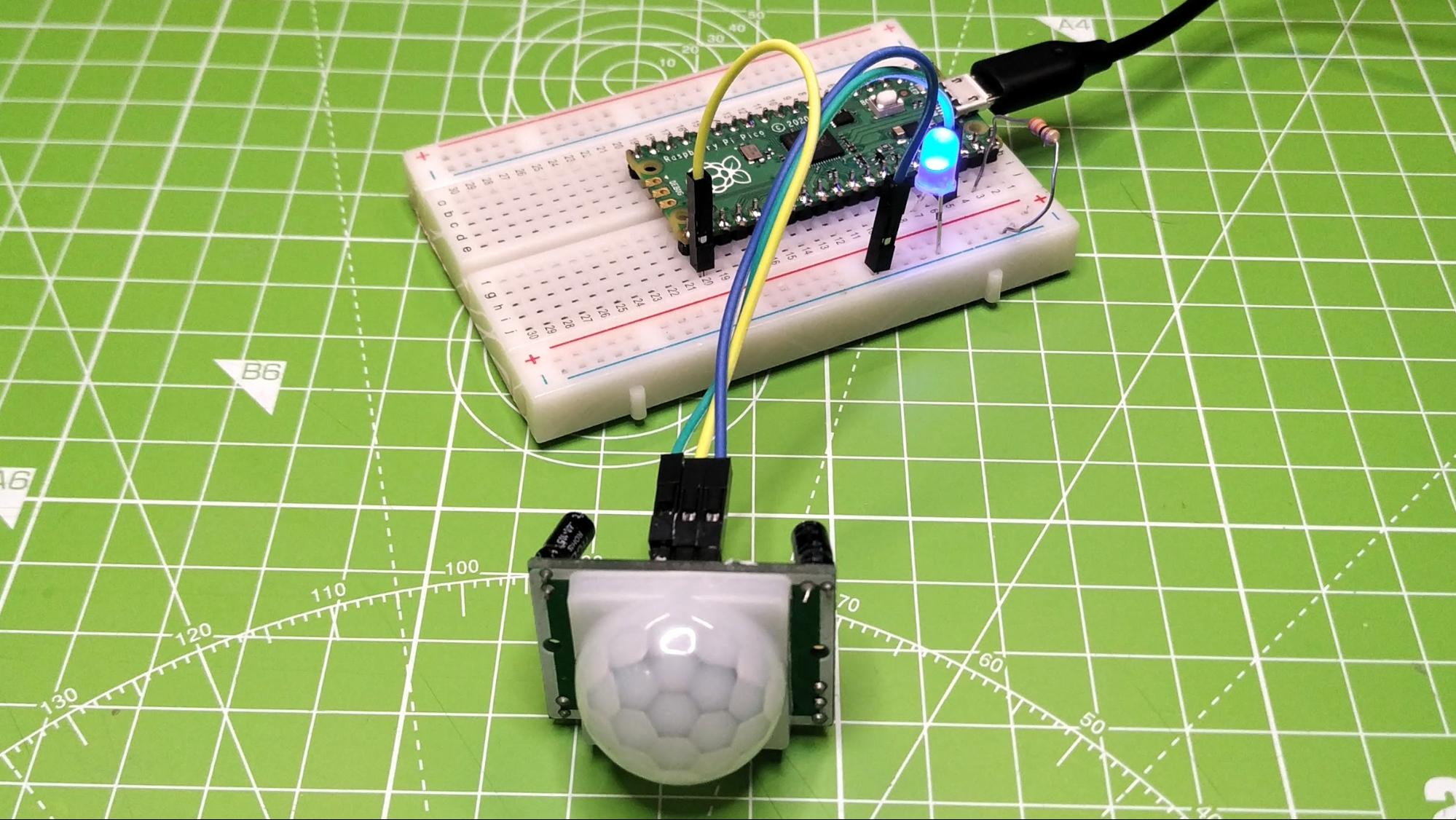
The Raspberry Pi Pico has a number of GPIO pins which we can use as inputs or outputs by simply configuring the pins in our code. In this guide, we shall learn how to work with inputs, in this case a sensor, and outputs in the form of an LED. At the end of this guide we will have a simple motion detector in 16 lines of MicroPython.
Before tackling this project, it would be beneficial to setup and test your Raspberry Pi Pico in our Raspberry Pi Pico Set Up Guide . We also use the circuit in that guide as the basis for this guide.
In this guide we shall be learning how to use the GPIO pins of the Raspberry Pi Pico as digital inputs and outputs which use high and low as a simple control method.
Setup
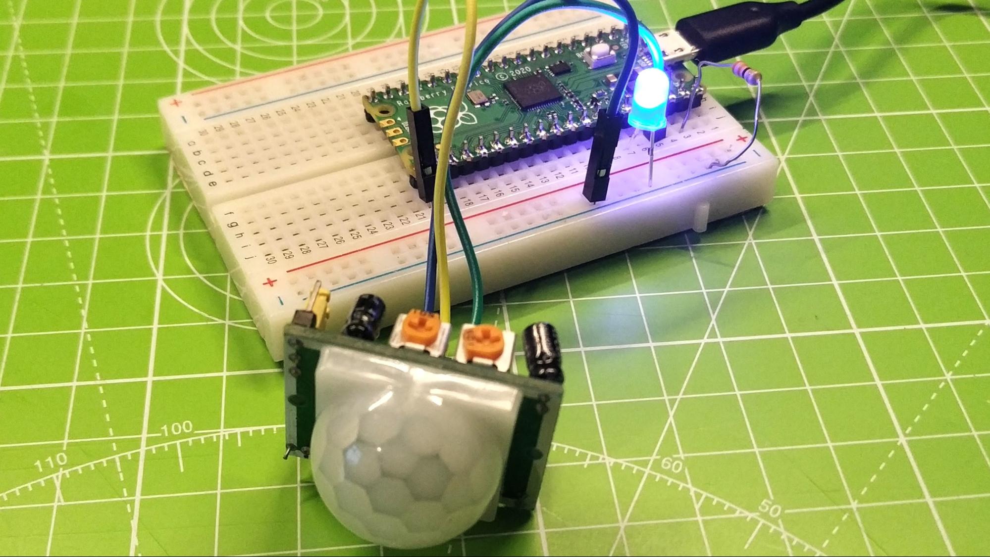
The circuit for this project adds one extra component, a Passive Infrared (PIR) sensor commonly used in home security systems to detect movement. In this project it will perform that same function, and our code will trigger an LED to turn on when the sensor reports movement.
Adding the sensor to the project requires:
- A half size breadboard
- An LED
- A 330 Ohm resistor (see 330 Ohm resistor color codes to identify)
- A PIR sensor
- 3 x Female to male jumper wires
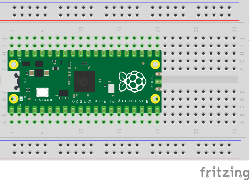
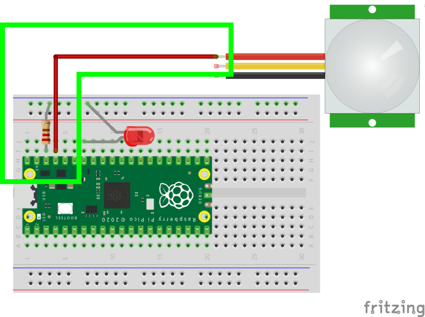
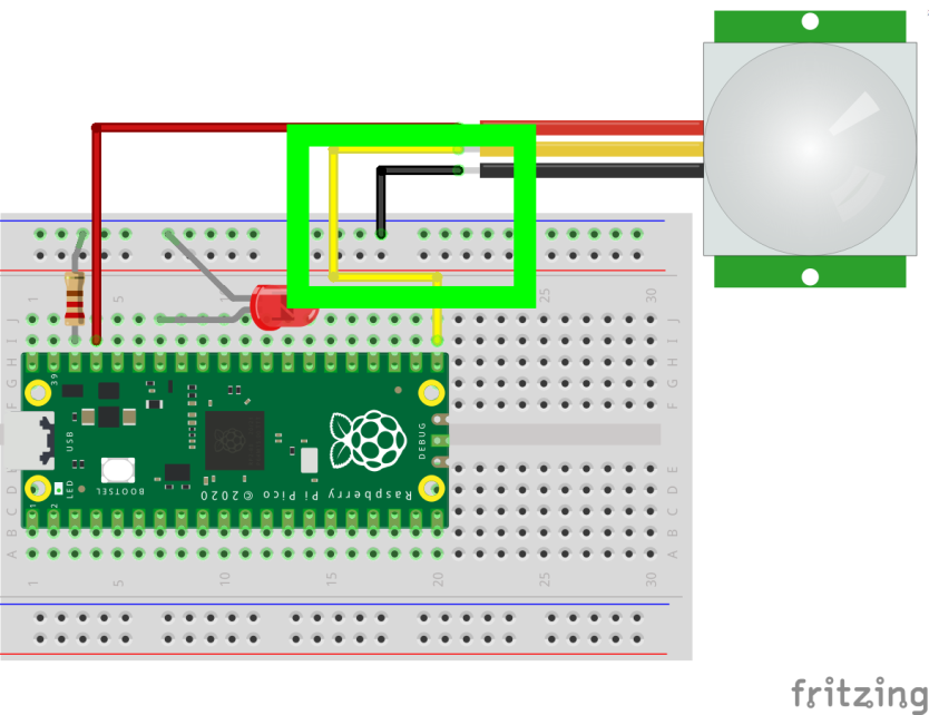
1. Insert the Raspberry Pi Pico into the breadboard so that it sits over the central channel. Make sure that the Micro USB port is at one end of the breadboard.
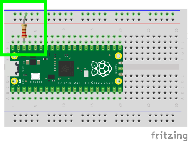
2. Insert a 330 Ohm resistor into the breadboard, one leg should be inline with GND, which is pin 38. The other leg should be inserted into the - rail of the breadboard. This provides us with a GND rail where all pins in that rail are connected to GND.
Get Tom's Hardware's best news and in-depth reviews, straight to your inbox.
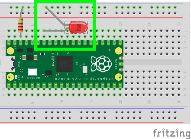
3. Insert an LED, with the long leg (the anode) inserted into the breadboard at pin 34, and the short leg inserted into the GND rail. The circuit is now built.
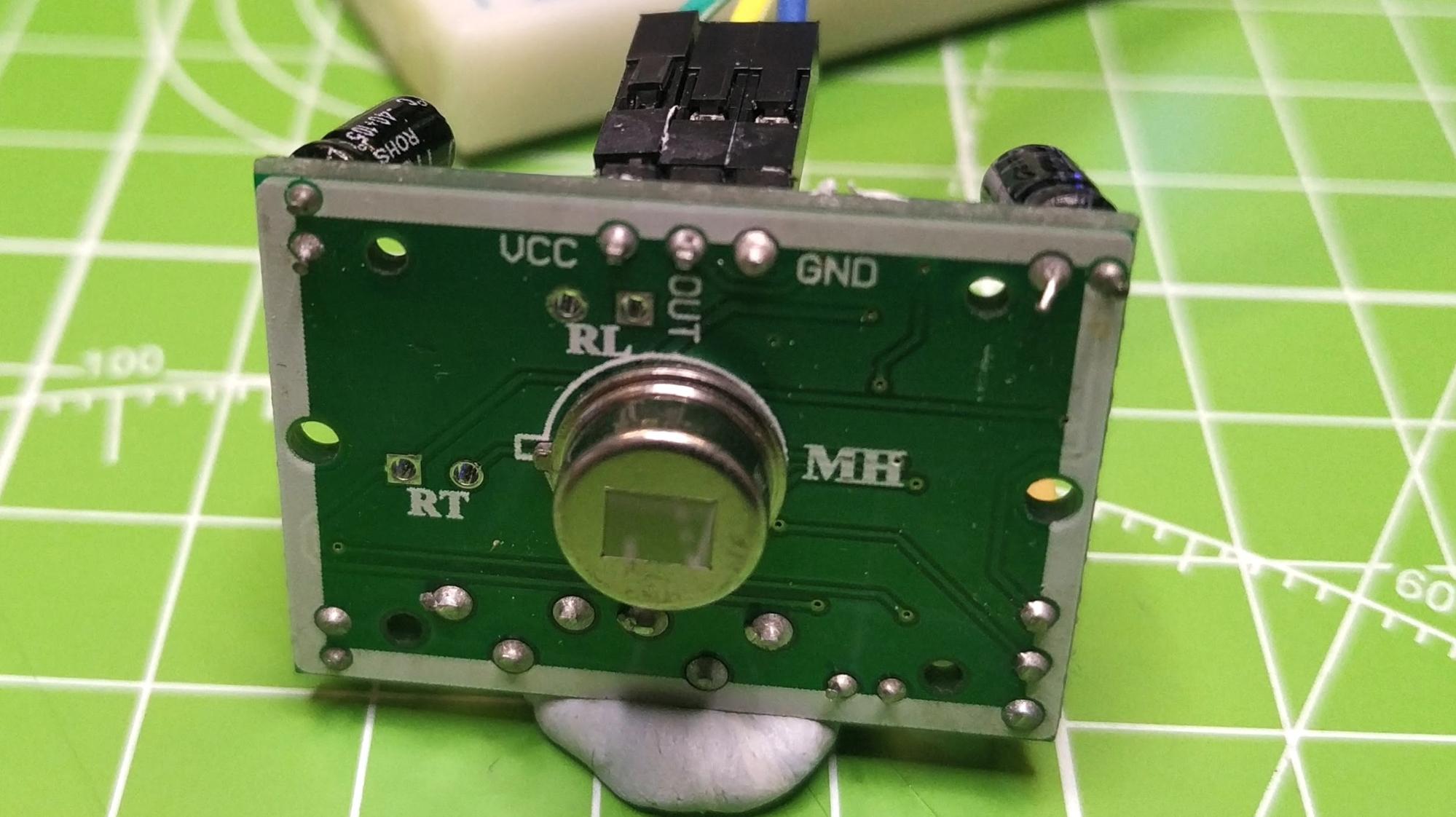
The PIR sensor has three pins. VCC, OUT and GND. The VCC pin is used to supply 3.3V of power from the Raspberry Pi Pico.
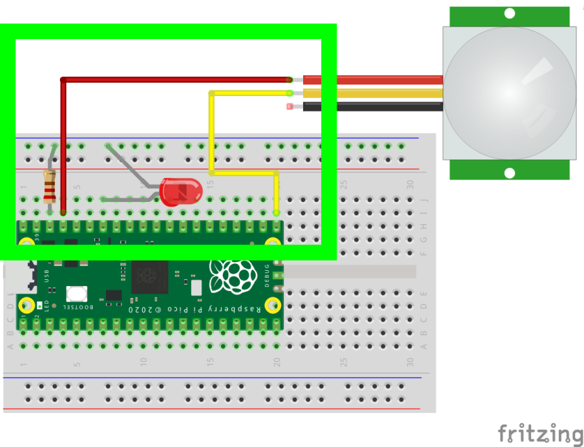
4. Using a jumper wire, connect VCC from the PIR to the 3.3V pin, (pin 37) which is just next to the resistor.
5. Use another jumper wire to connect the OUT pin of the PIR to pin 21 of the Pico.
6. Connect the GND pin of the PIR to the GND rail of the breadboard.
7. With the circuit built, connect the Raspberry Pi Pico to your computer using a micro USB lead. Open the Thonny application.
We now move to coding the project and we build upon the code used in the Getting Started project to include an input, our PIR sensor, and a conditional test to check whether the sensor has been triggered.
1. Import the Pin class from the machine library, then import utime. These libraries enable us to respectively communicate with the GPIO and to control the pace of our project.
from machine import Pin
import utime
2. Create an object, “led” which is used to create a link between the physical GPIO pin and our code. In this case, it will set GPIO 28 (which maps to physical pin 34 on the board) as an output pin, where current will flow from the Raspberry Pi Pico GPIO to the LED. We then use the object to instruct the GPIO pin to pull low., In other words this will ensure that the GPIO pin is turned off at the start of our project.
led = Pin(28, Pin.OUT)3. Create another object, “pir”. This object is used to create a connection between our code and the GPIO pin used for the OUT connection from the PIR. By default, the PIR sensor OUT is pulled high, and when movement is detected the PIR pulls the OUT pin low. To ensure that the sensor works correctly, we set the pin as an input, and then pull the GPIO pin high.
pir = Pin(16, Pin.IN, Pin.PULL_UP)4. Ensure that the LED is turned off at the start of the project, then wait for three seconds before moving on. These two lines ensure we do not see a “false trigger” from the LED, and give the sensor some time to settle before use.
led.low()
utime.sleep(3)
5. Inside of a while True loop, a loop with no end, use a print function to print the current value of the GPIO pin used for the PIR sensor. This will return a 1 if there is no movement, and a 0 if there is.
while True:
   print(pir.value())
6. Create a conditional test that checks the value stored in pir.value. If the value is 0, movement detected then print a message to the Python Shell. Then turn the LED on (high) and pause for five seconds, keeping the LED lit for that time.
if pir.value() == 0:
       print("LED On")
       led.high()
       utime.sleep(5)
7. The last part of the conditional test is activated when there is no movement detected. Use an Else condition to print a message to the Python Shell, then add a line to turn the LED off (low) and then pause for 0.2 seconds. Then the loop repeats and the conditional test is run again.
else:
       print("Waiting for movement")
       led.low()
       utime.sleep(0.2)
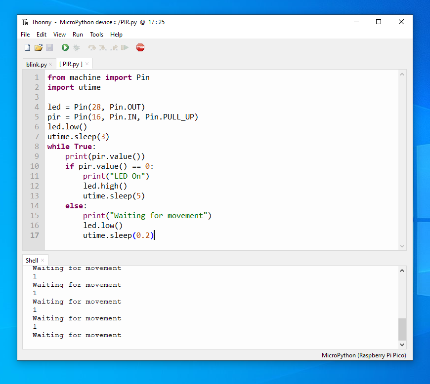
8. Click on Save and choose to save the code to the MicroPython device (Raspberry Pi Pico). Name the file PIR.py and click Ok to save. Your code should look like this.
from machine import Pin
import utime
led = Pin(28, Pin.OUT)
pir = Pin(16, Pin.IN, Pin.PULL_UP)
led.low()
utime.sleep(3)
while True:
   print(pir.value())
   if pir.value() == 0:
       print("LED On")
       led.high()
       utime.sleep(5)
   else:
       print("Waiting for movement")
       led.low()
utime.sleep(0.2)
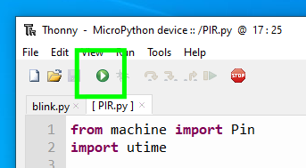
9. To run the code, click on the Green play / arrow button and the Python Shell will update to say “Waiting for movement” and “LED On”. The PIR sensor is exceptionally sensitive and at first you may see a few false triggers, but the sensor will settle.

Les Pounder is an associate editor at Tom's Hardware. He is a creative technologist and for seven years has created projects to educate and inspire minds both young and old. He has worked with the Raspberry Pi Foundation to write and deliver their teacher training program "Picademy".
-
mideal Trying this code with the SR505 (the smaller version of the PIR sensor), omitting the LED connection and its code.Reply
I simply wanted to test the motion sensor (to control a servo afterwards).
There is a motion detection every approx. 6 seconds - even when I put it into a black bag covered with a black cloth and no movement of nothing at all.
Any idea? -
mideal NOW I found it. ... it's a standard delay time.....Reply
More investigation needed, or I need a SR501 like in your example.
