How to Use Raspberry Pi and Arduino Together
Connect an Arduino board to your Raspberry Pi and take advantage of unique capabilities like a built-in ADC chip.
The Arduino and Raspberry Pi are two very different products, but they both cater to eager hackers and makers. What if we could connect an Arduino to a Raspberry Pi and use it as a slave device: one that reacts to input and sends the output to our Raspberry Pi via Python?
After all, the Arduino, while not a full-fledged computer, has a few things it does better, like converting analog-to-digital with its built-in ADC chip. To connect the Arduino to the Raspberry Pi, we are going to need some special software, and that is where this tutorial starts.
Software Setup to Use Raspberry Pi with Arduino
Before we can write any Python code we need to download and install Arduino IDE for Linux ARM 32-bit. Once it is installed, we need to add the user "pi" to the correct group to send data to the Arduino. So to add pi to the group, open a terminal and type the following:
$ sudo usermod -a -G dialout piThen reboot your Raspberry Pi before continuing. With the Pi rebooted, open Arduino IDE, and select File > Examples > Basic > Blink and then go to Tool > Board and select your board. For our tests, we used an Arduino Uno.
Then go to Tools > Port and make sure the port for your board is selected. Now click on Sketch > Upload (or click on the arrow in the menu) to upload the code to the Arduino. After a few seconds, the built-in LED of the Arduino should flash on/off slowly. This proves that we have a working unit.
With the test complete, we can now flash a special sketch that will enable us to talk to our Arduino with Python. Go to File > Examples > Firmata > StandardFirmata and flash this sketch to your Arduino. Once it is flashed, you can close the Arduino IDE. To install the pyFirmata library, open a new terminal and type the following:
$ sudo pip3 install pyfirmataProject Hello World on Raspberry Pi with Arduino
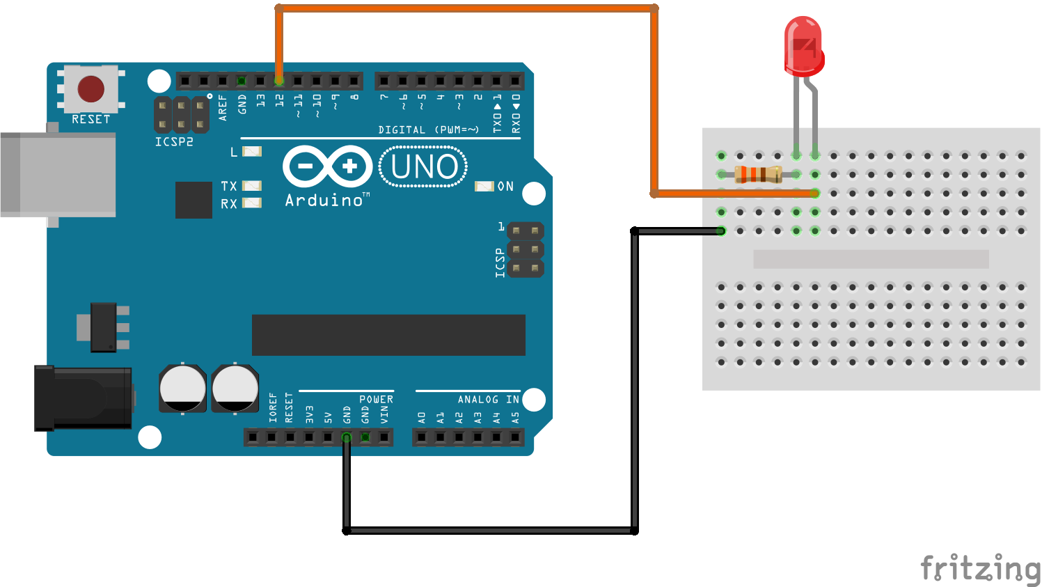
To test that our Arduino will work with Python we will write a quick script to turn on an LED connected to pin 12 of the Arduino. Please see the diagram for the Connections.
Get Tom's Hardware's best news and in-depth reviews, straight to your inbox.

Plug in the Arduino, and in the terminal type the following code. Look for USB devices such as ttyUSB0 and ttyACM0. Make a note before moving on.
$ dmesgUsing your favourite Python 3 editor (IDLE, Thonny, nano, Vim), create a new file and name it LED_test.py. We shall now write some Python code into this file. Start by importing two classes from the pyFirmata library, which will enable our code to connect to the Arduino. We can then import the sleep function from the time library, by typing:
from pyfirmata import Arduino, util
from time import sleep
The next step is to create an object called board that will be the connection from our Pi to the Arduino. For this, we shall need to use the USB device information from dmesg . In our case our Arduino was at ttyUSB0.
board = Arduino('/dev/ttyUSB0')A variable called led is used to store the Arduino pin number. You create it by adding the line:
led = 12Inside of a while True loop, we can write the code that will turn the LED on and off every 0.2 seconds. We will call the object board, with a class to control the pin digitally (0,1) and then write 1 to the pin to turn it on. Note that we use the variable led to identify the pin. Then we sleep for 0.2 seconds, before turning the pin off and sleeping once more.
while True:
board.digital[led].write(1)
 	sleep(0.2)
 	board.digital[led].write(0)
 	sleep(0.2)
Save the code and then run it from your editor (IDLE Run > Run Module/Thonny Run > Run Current Script) and after a few seconds the LED connected to the Arduino will flash, proving that we have a working connection.
The final python script should look like this:
from pyfirmata import Arduino, util
from time import sleep
board = Arduino('/dev/ttyUSB0')
led = 12
while True:
        board.digital[led].write(1)
 	sleep(0.2)
 	board.digital[led].write(0)
sleep(0.2)
Flashing LED Lights with Raspberry Pi and Arduino
Now let’s make a new project. This will be an LED that flashes, but the interval between each flash is controlled via a potentiometer, an analogue electronic component –- something that the Raspberry Pi cannot ordinarily use without extra ADC (analog-to-digital conversion) boards.
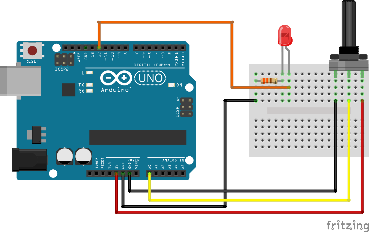
We can use the value returned from the Arduino to control the speed at which the LED flashes. We will add the potentiometer to the existing LED test circuit that we have just built and tested. Please see the diagram below for more information on this.

We’ll start the code for this project In a new blank file, using the same lines to import and configure the pin being used on the Arduino.
from pyfirmata import Arduino, util
from time import sleep
board = Arduino('/dev/ttyUSB0')
led = 12
To read the analogue values from the Arduino we need to create a thread that will run and not interrupt the main code. We should create an object called it and then connect this to the Arduino, before then starting the thread.
it = util.Iterator(board)
it.start()
board.analog[0].enable_reporting()
The main body of code is a while True loop, which will read the current value of analogue pin 0, which is connected to the potentiometer, and store the value in a variable called value. This value will then be printed to the Python shell.
while True:
     value = board.analog[0].read()
     print(value)
A conditional test is now applied to the value variable. If the value has no data, then it will return none, and this will crash the code. Therefore an if condition checks the value, and if it is none, it changes it to 0.
     if value == None:
          value = 0
Another condition to test this is if the value is greater than 0.05, the analogue values returned are between 0.0 and 1.0. If the value’s greater than 0.05 the LED is turned on, and the sleep interval, used to keep the LED on/off by pausing the code, is controlled by the value.
     elif value > 0.05:
          board.digital[led].write(1)
          sleep(value)
          board.digital[led].write(0)
          sleep(value)
The final lines of code are an else condition, which turns the LED off if the value is less than 0.05. Save the code and run. Now turn the potentiometer and watch the LED come to life. Your final python code should look like this:
from pyfirmata import Arduino, util
from time import sleep
board = Arduino('/dev/ttyUSB0')
led = 12
it = util.Iterator(board)
it.start()
board.analog[0].enable_reporting()
while True:
     value = board.analog[0].read()
     print(value)
     if value == None:
          value = 0
     elif value > 0.05:
          board.digital[led].write(1)
          sleep(value)
          board.digital[led].write(0)
          sleep(value)
This article originally appeared in Linux Format Magazine Issue 260.

Les Pounder is an associate editor at Tom's Hardware. He is a creative technologist and for seven years has created projects to educate and inspire minds both young and old. He has worked with the Raspberry Pi Foundation to write and deliver their teacher training program "Picademy".
-
glenn_n Why not just use an A/D converter? There's less hardware, much less complicated, you only need to program the R-Pi, don't need to also write code for Arduino. This article shows you the way (except the software bits are outdated): https://learn.adafruit.com/raspberry-pi-analog-to-digital-convertersReply -
Dr.J Reply
Because its fun and after learning that way knowing will be fun as wellglenn_n said:Why not just use an A/D converter? There's less hardware, much less complicated, you only need to program the R-Pi, don't need to also write code for Arduino. This article shows you the way (except the software bits are outdated): https://learn.adafruit.com/raspberry-pi-analog-to-digital-converters