SSD Recovery: How Pros Bring Flash Memory Back To Life
Scanning Stations
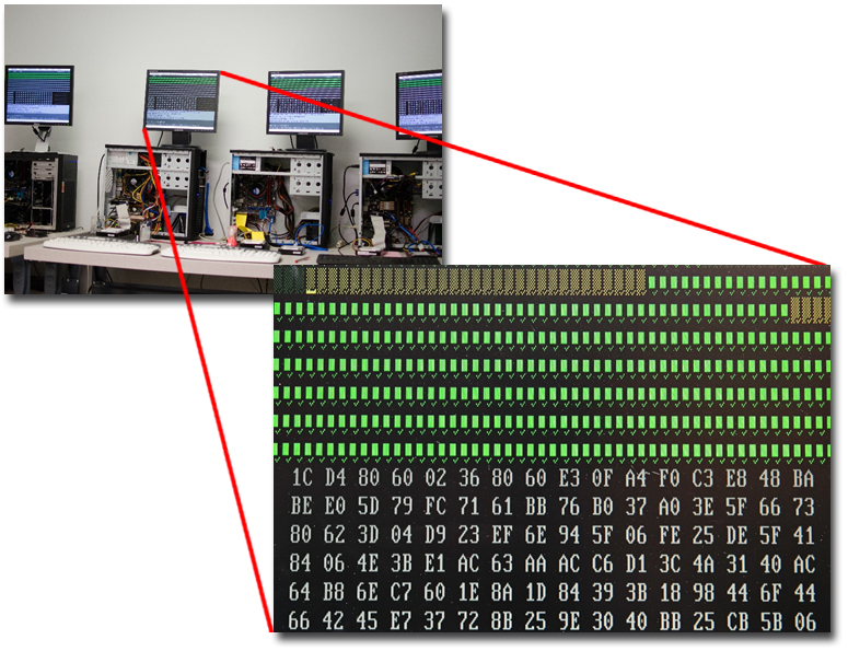
Once chips are connected in such a way that they can be read by external devices, Flashback brings in its house-built systems for reading the data. The systems are fairly simple except the fact that they have Flashback’s special imagers in them that allow techs to jump around to different sectors, control time-outs, and so forth. If something is reading more slowly than normal, the imager can force drives to jump to the next good sectors and keep going in order to get the most data possible as quickly as possible.
“We can go forward and backward and jump around,” says Chozick. “We can tell it to just scan the MFT of the drive and only image the allocated data instead of trying to get free space, so we can do the job very quickly. Sometimes, you’re fighting against a device still in the process of failing, and sometimes you’ve got a client who just needs one or two things back with absolute haste.”
Stock It—It’s A Socket
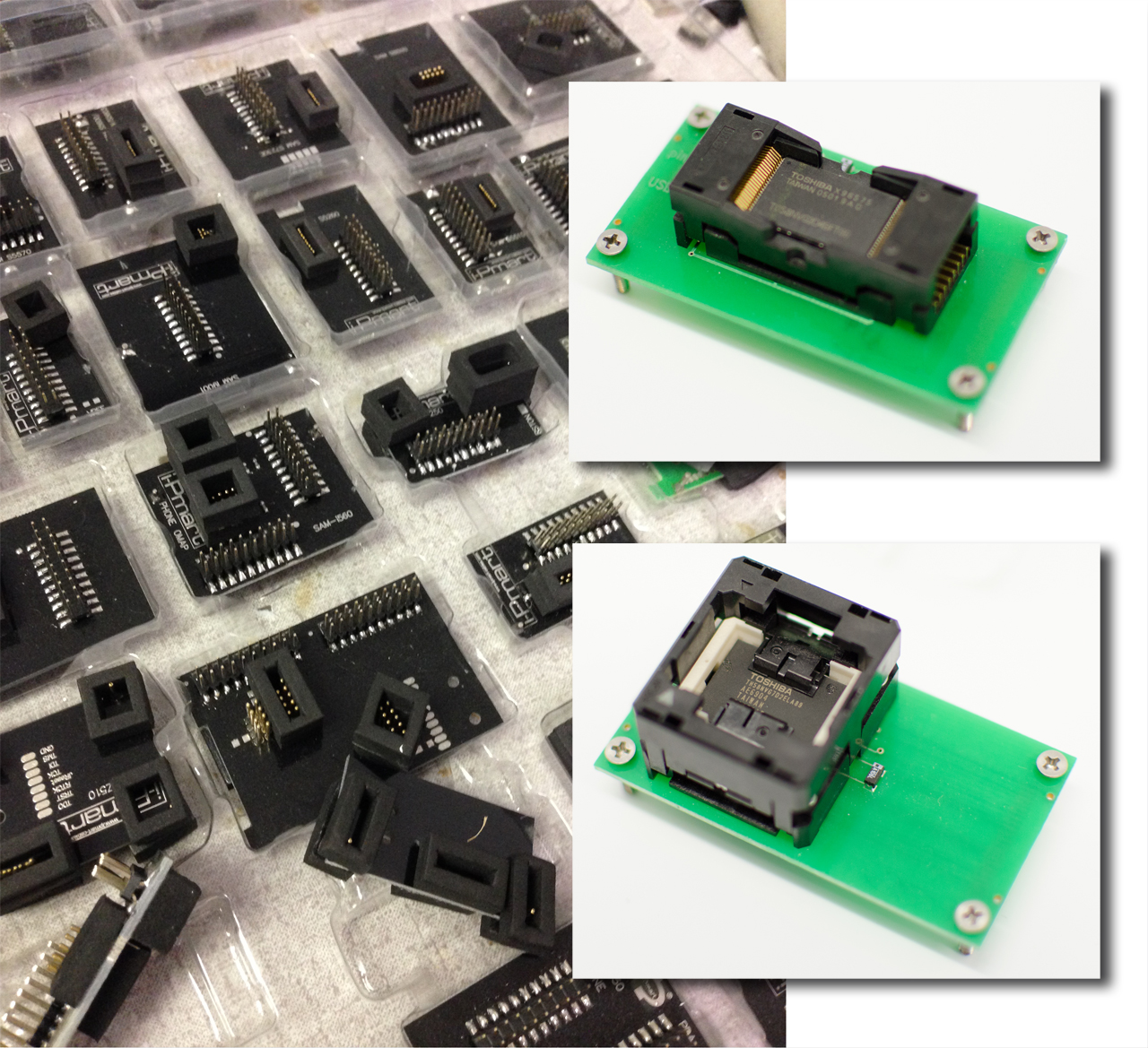
In order to connect flash chips to its reading systems, Flashback employs a startling range of chip mountings. Highlighted here are one type of adapter used to read TSOP48 chips as well as a TLGA reader. Within the adapters, each of the socket pins touches one of the pins on the memory chip. The adapter screws into an underlying board with data contacts for connecting with the TSOP socket. The lower board, in turn, features a USB interface for linking into the scanning station systems.
Data Spaghetti
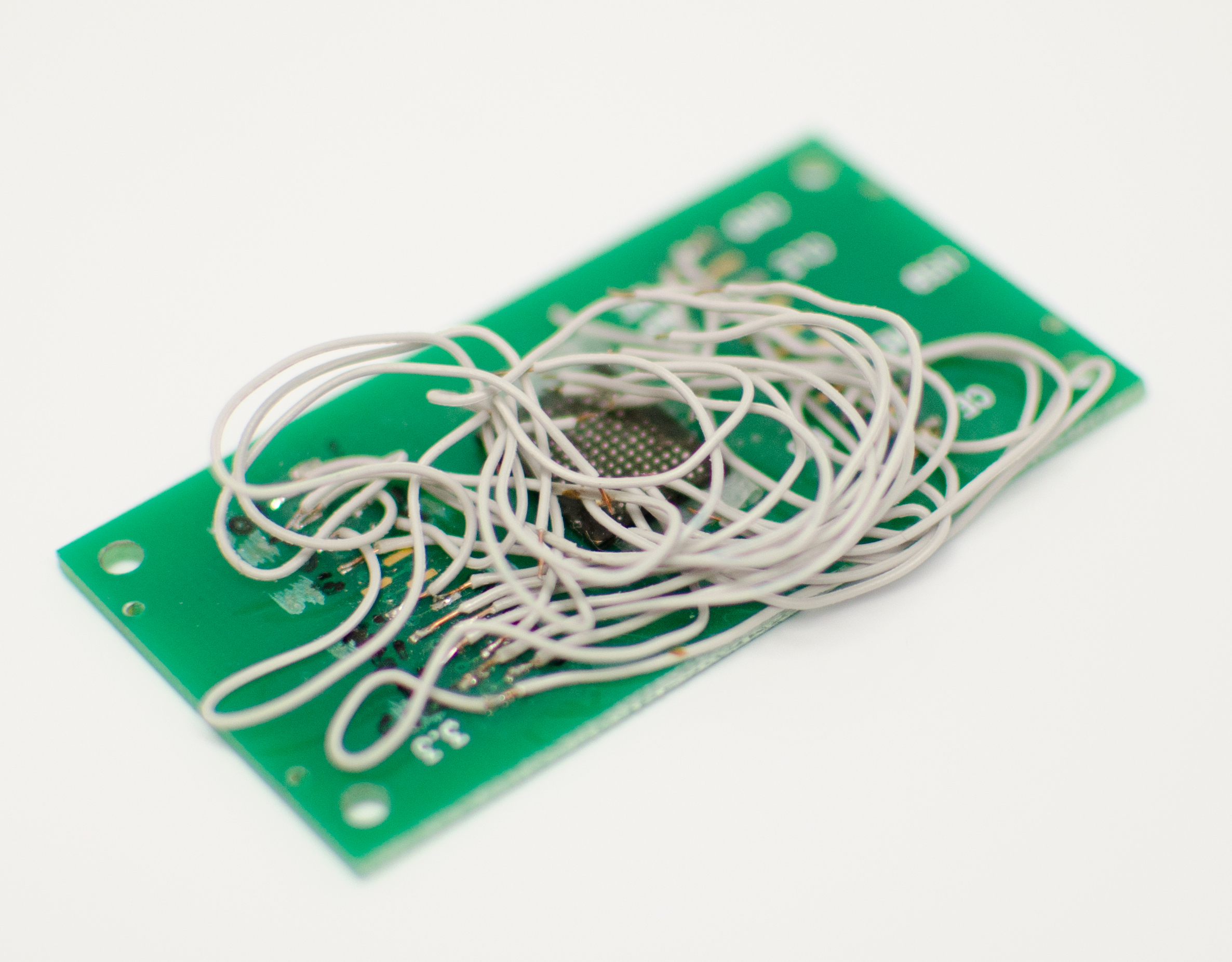
Remember the memory chip pulled off that HTC phone? Here it is again, partially wired up for reading. Flashback had these PCBs custom made for this exact use. They hook up to a USB device programmer. The holes in each corner help secure the chip to an underlying board. With the TSOP adapter shown on the prior page, each of the socket pins touches one of the pins on the memory chip. But in this “spaghetti” shot, all of the chip pads are exposed so that techs can solder right onto them instead of requiring a socket. Since there are so many monoliths and pin-outs, Flashback needs to wire to specific data points and solder directly to the chip.
This is an 8-bit chip, as evidenced by there being eight wires connected to the PCB. If this has been a 16-bit product, there would be twice as many wires.
Reading For Hours
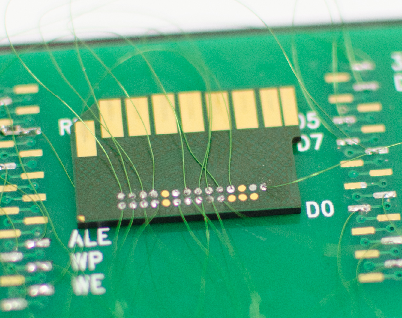
Wiring up monolith chips follows on much the same “spaghetti” approach as seen in the last page. Different devices require different wiring, but the idea stays the same, with each lead connecting to a distinct feature. The lead on the top-right, for example, is 3.3 V power. Examining this process, you begin to appreciate how time-intensive simply extracting data from chips can be.
Welcome To The Jumble
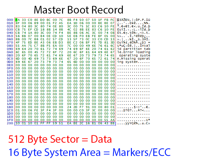
Let’s take a look at what recovery techs have to work with. What you see here are the contents of a raw data dump of an SSD’s master boot record. The data is jumbled up by the algorithms applied by the controller when optimizing read and write speeds, wear leveling, etc…
Get Tom's Hardware's best news and in-depth reviews, straight to your inbox.
“Once we’ve read in the chips,” says Chozick, “we simply have a pile of raw data. In this example, the flash memory chip has a 528-byte sector. The first 512 bytes are used for the data. The last 16 bytes are used to store information about what order the data is in and error correction information. We call this the service area. So, when we first look at a flash dump in hex(idecimal code), we need to find known data structures to see how the data is mixed up.“
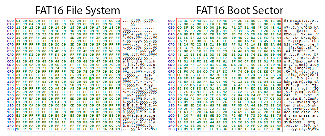
This and the following page show examples of known data structures in hex.
FAT Under The Microscope
Shown here are a FAT16 file system and a boot sector.
“The MBR is usually sector 0,” says Chozick. “Now, it’s not going to be 0 in the flash dump, but we can at least find where that is and determine the known structure of data. We know where it is, how far it is from the boot sector, and so on. You can see it in the next image. It’s like evidence gathering. We find the MBR, the boot sector, the FAT. Now we can look at these known structures and figure out how to put everything back together.”
Chozick notes that sometimes techs can’t find any of these structures, usually because of some algorithm applied to the device. Some algorithms will invert all of the data bits. If that approach is discovered, techs know to reinvert it back. Some algorithms will join everything by a single byte instead of a whole sector, so every byte will be on a different flash chip. This necessitates rejoining those data by byte rather than by the whole sector. Some algorithms will use ciphers, which makes things, understandably, even harder. For a process driven by computer, recovery often proves very manual.
Come Back Together
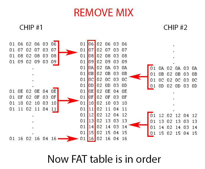
Let’s take a closer look at the sector data in a case wherein information is scattered across multiple memory chips. You can see what the first part of each sector looks like.
Hex numbers are supposed to run in this order: 0, 1, 2, 3, 4, 5, 6, 7, 8, 9, A, B, C, D, E, F, 10, 11, 12, 13, 14, 15, 16, 17, 18, 19, 1A, 1B, 1C, and so on. On flash chip #1, though, you can see that the hex order is broken twice. First, there’s a jump from 09 to 0E, then there’s another four-sector gap between 11 and 16. What happened to the corresponding data? The answer sits waiting on flash chip #2.
Back In Order
Technicians need to rejoin these separated 2112 bytes (528 bytes per sector * 4). When joined, the result will look as you see it here.
Now imagine if there are 64 flash dumps that have to be combined! Why 64? Because a single chip might not have only one dump. Some could have four—one for each bank within the chip. So take the 16 flash chips you might find on an SSD, multiply by four, and that’s 64 dumps to put back together.
Before And After
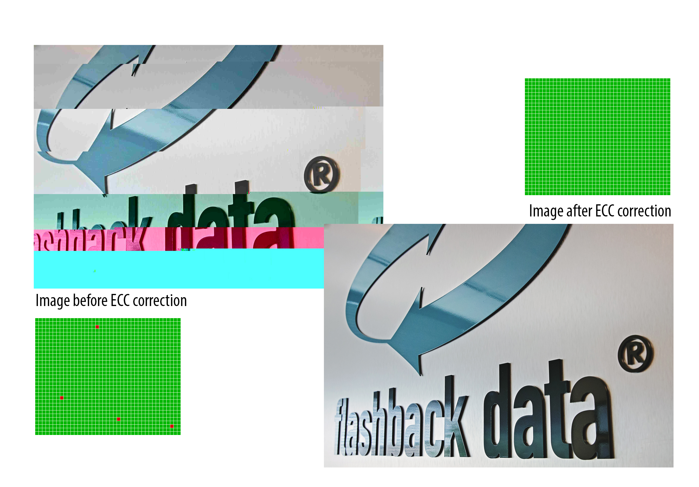
It can be difficult to visualize what all of these byte-level gyrations mean at the macro level. An empty cell on a spreadsheet (or a corrupt file, for that matter) doesn't quite capture it.
Flashback supplied this image to illustrate the concept. Some examples will still have their header and part of their data intact, so they may look close, but they could be jumbled up or render as half-pictures with gobs of noise all over them.
Starting with an originally corrupted JPEG, technicians applied ECC correction and block translation to order data and remove bit errors that were handled by the controller. They also reordered and removed the service area from the reassembled data so as to have a clean, continuous data stream.
The End Result
After hours of manipulation and repair, even using algorithms that help automate some of the data restitching, Flashback technicians finally have information that looks like files and folders. Everything is back in order. The burning question remains, though, as to whether the data is sound and in its original form.
In part, such things can be checked by file headers. SD cards and similar media tend to contain a lot of images, and those are pretty easy to check visually for errors. ECC errors in specific files are fairly easy to spot. Other data types can be harder. Utilities can tell technicians by the file header if they think a good file is sound, but they may not flag a bad sector that would be plainly visible to an observer.
“With most customers, we try to be pretty hands-on,” says Chozick. “We ask them what they’re looking for and test files for them if they ask us to. If it ends up being something where we can’t recover the directory structure, we might just have to do it by file header. This is like a raw recovery where we won’t get file names anymore. We’ll pull off data and sometimes get people more than they thought they had, because we might also get deleted information. Sometimes we might find the FAT table is completely damaged, and then we’ll have to do this sort of raw-type recovery.”
-
Eggz What did I just look at? Maybe it's displaying wrong on my screen, but there were no words and the pictures were pretty bad.Reply -
artk2219 Thanks for the story! Very cool to get a general overview of the flash media based file recovery process.Reply -
TyrOd "In an earlier article we did on data recovery, at least one commenter noted that essentially anyone could get into the recovery business and that Flashback was a small fry operation on a completely different level than more recognized names. Of course, the proof is in the recovery results and the client roster, which includes a broad spectrum of commercial and government accounts."Reply
No. Nobody was conflating the physical(or financial) size of the business or name recognition with the level of their technical capabilities.
In fact, the biggest and most recognized data recovery labs are the most notorious for abandoning attempts at complex recoveries due to the shear volume of cases they receive.
The point that you are still missing is that everything you saw at flashback was commercially available to start-ups.
In fact there are literally dozens of labs out their that have sprung up in the past 10 years with the same array of tools.
One laughably obvious example of the basic marketing spin is slide 12.
Where exactly do you think "Flashback's Special Imagers" came from?
Hw exactly do you call a commercially available tool,sold by the thousands to data recovery start ups for years "Special".
Also, I literally Laughed out loud when I read the bit about ASCLD cert.
Do you really believe that ASCLD Lab Cert actual says anything about the technical capabilities of a forensic lab?
ASCLD lab is an operational certification and it's completely irrelevant to Data Recovery Labs on the technical level.
Hoiw do I know this? because I called them and asked.
I verbatim said "what criteria are used to test for technical the capabilities of a proprietary piece of hardware in Recovering forensically sound images?"
There response was "...as long as it does what you say it does"
Funny, right?
Though Flashback seems to be making an honest effort, at least from a marketing standpoint, of doing complex recoveries(like monolithic/SSD Flash rebuilds) it says very little about their actual ability to minimize corruption and maximize recovered data.
I was actually impressed by the thoroughness of this article, but unfortunately it could have been done at dozens of other labs with similar technology. -
TyrOd I also want to mention that ASCLD lab is definitely a robust qualification for Forensic Labs. But it only extend it's relevance to the Computer Forensics aspects that only sparsely overlap with physical data recovery.Reply
you actually see a lot of this cert padding among bigger labs, because people don't understand how different a data recovery Lab is from the rest of the IT world.
For example: If you use a piece of encryption software or Virtual machine platform of some kind and something goes wrong, how useful is having a engineer certified by the software maker?
For the IT professional, the answer is probably "useful' generally speaking.
What about when their are physically damaged sectors and it's not possible to recover a few hundred sectors?
Then what?
Well you call the encryption software maker...you get elevated to their highest level of support...and they tell you it's not possible...in fat they don't even understand the difference between bits and sectors, claiming literally every single bit has to be read to decrypt with their software.
That's the normal everyday of how far a certification, even from manufacturers will get you in the Data recovery field.
Beyond that you're on your own to develop solutions. -
Eggz Reply13365168 said:Texts are on the right side of the images. Perhaps you need to update your browser to make images along with text visible.
Thanks. For some reason, the computer I was using didn't update the text corresponding to pictures. So when I scrolled photos, the text for only the first photo was displayed. Got it now. Great article! Thanks for keeping a flow of stuff like this. -
smeezekitty This is why on the fly encryption is a bad idea. And not only that, its pointless.Reply
Because if someone has access to the drive it does exactly zero. It only stops reads directly from the flash chips.
