Why you can trust Tom's Hardware Our expert reviewers spend hours testing and comparing products and services so you can choose the best for you. Find out more about how we test.
Results: Power Consumption And Temperatures
Power Consumption
These aggregated results are a lot more telling than extremely short peaks due to the latter’s very brief nature. We took a look at a total of eight different scenarios.

Some of the applications consume more power over time. This is due to the CPU heating up. We found that the difference between a cold and fully warmed up CPU can be up to 3W. If these 3W are interpreted as leakage currents, then this is actually a very good result.
We took the average of the power consumption curves after the CPU had reached its full operating temperature and put the results in a bar graph to provide a summary.

Temperatures
Keeping the processor cool is more important than ever due to AMD’s XFR and related technologies. Lower temperatures have the potential to translate to higher clock frequencies. This is why we used a custom water cooling loop, which was very much needed during the rendering benchmarks with all cores running at 3.8GHz.
The CPU diode that AMD uses should be closest to the Tpackage value, which is the part of the CPU that has to endure the most heat in the long run. Tcore doesn’t matter as much anymore due to the massive areas that the cache takes up these days.

Infrared Video and CPU Temperatures
We decided to make an infrared video and spare no expense. Shooting it also required a degree of bravery, since we had to take off the CPU cooler to record it. We installed the camera so that it was pointed downward directly facing the CPU’s heat spreader. The camera’s distance from the processor was a function of the camera’s focal length and efforts to avoid any reflections caused by the camera’s lens and the metallic surface of the heat spreader.
We also applied a total of six thin layers of special lacquer used in board manufacturing to the heat spreader. This is necessary because the pure metal’s temperatures can’t be measured accurately due to its emissivity changing along with its temperature. After the usual calibration, we recorded the following video.
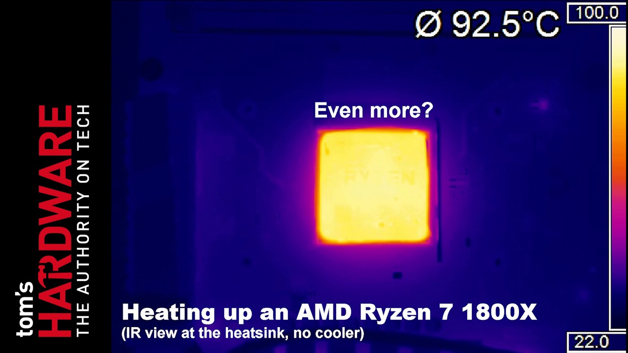
It’s easy to locate the processor’s die this way. It appears to be long and narrow in shape. The heat spreader’s uniform heat distribution indicates that there’s sufficient contact between the die and the heat spreader, especially in light of the fact that we weren’t able to assert any pressure on the heat spreader while we were recording the video. We recently discovered that the die is soldered to the Integrated Heat Spreader (IHS), which is typically much more efficient than Intel's technique of using thermal paste.
AM4 Kit Incompatibility
One of the hardware components that’s seen some changes is the AM4 motherboard’s backplate. It’s different in two very significant ways: The distance between the holes has changed and the threaded pins are longer. Even though AMD seems to have informed manufacturers of the first change, they apparently forgot about the second one.

We asked the manufacturers, and they confirmed that this is what happened. This means that if the original motherboard backplate’s used in conjunction with longer screws, then the cooler might not be held against the processor tightly enough.

The solution involves adding the needed millimeter by using either thick ring washers or suitable nuts. We’ll keep in touch with the manufacturers, since the problem doesn’t seem to affect all of the kits.