Testing EVGA's GeForce GTX 1080 FTW2 With New iCX Cooler
Does a new heat sink translate to new success? EVGA complements its existing technology with some on-board sensors and gives enthusiasts access to asynchronous fan control.
Cooler Design And Technical Implementation
Sensors in abundance
Based on our close examination of graphics card circuit board layout, we know that the usual tools only read the GPU diode’s temperature. You’ll sometimes see a reading for VRM or VRM2, but that’s simply the PWM controller’s temperature. EVGA wants to prove it can provide a much more thorough picture of thermal performance, though.
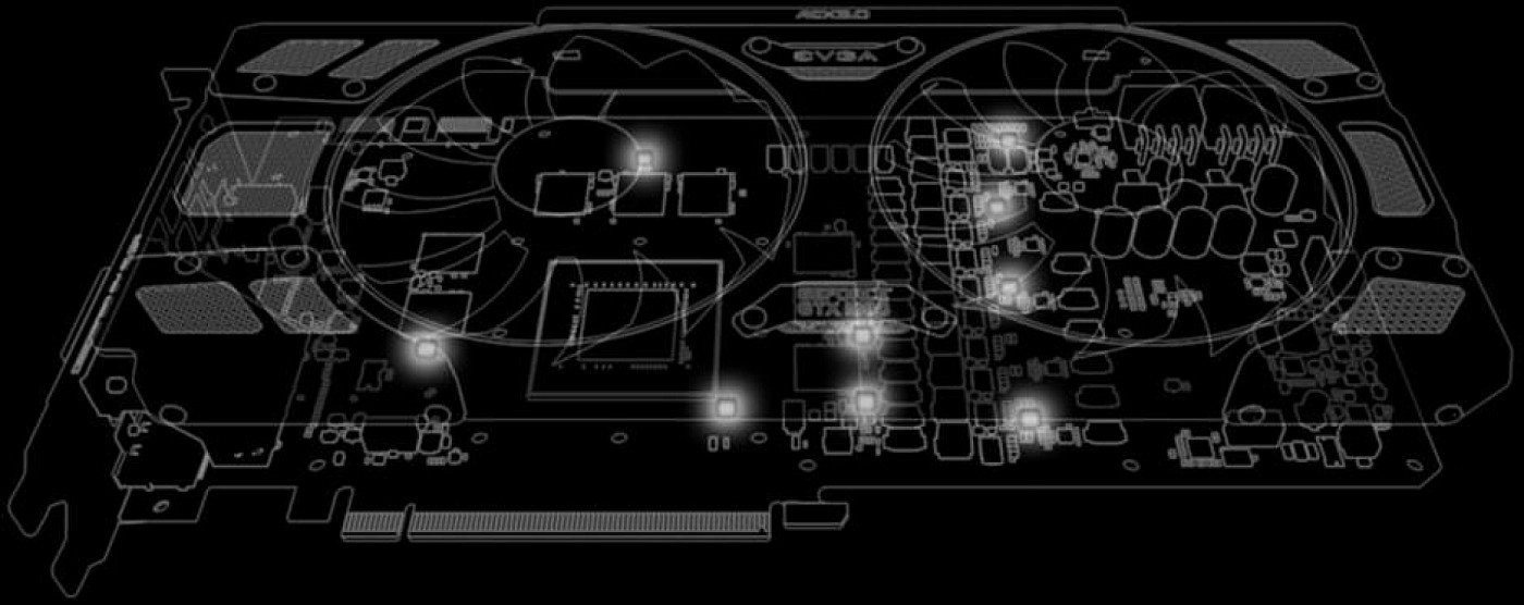
On its slightly modified board, the company places a total of nine thermal sensors in locations where hot-spots may occur. The measured values can be displayed and also logged by EVGA’s Precision Software. Truly, hardcore control freaks have to love that amount of information provided in real-time. It might even be too much goodness, though. After all, worrisome hot-spots only really occur in two places on the cards we’ve dissected.
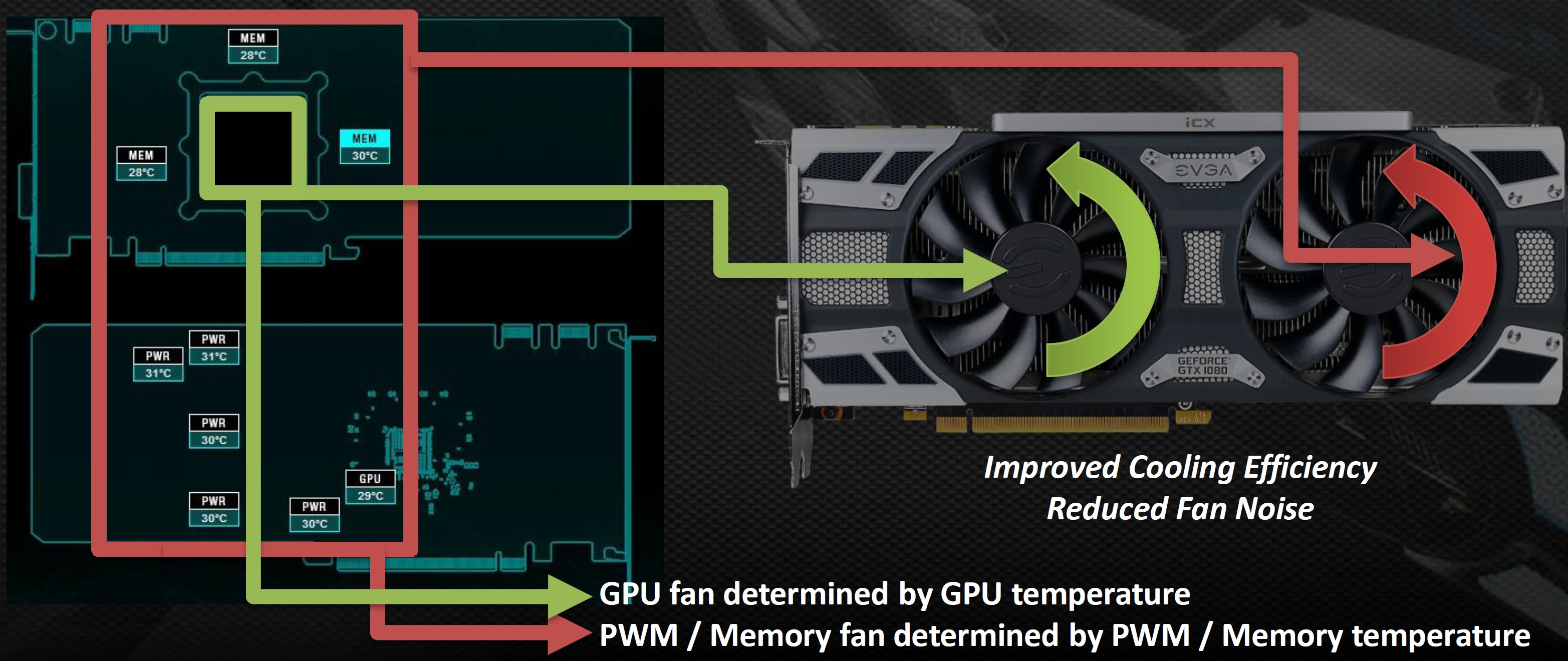
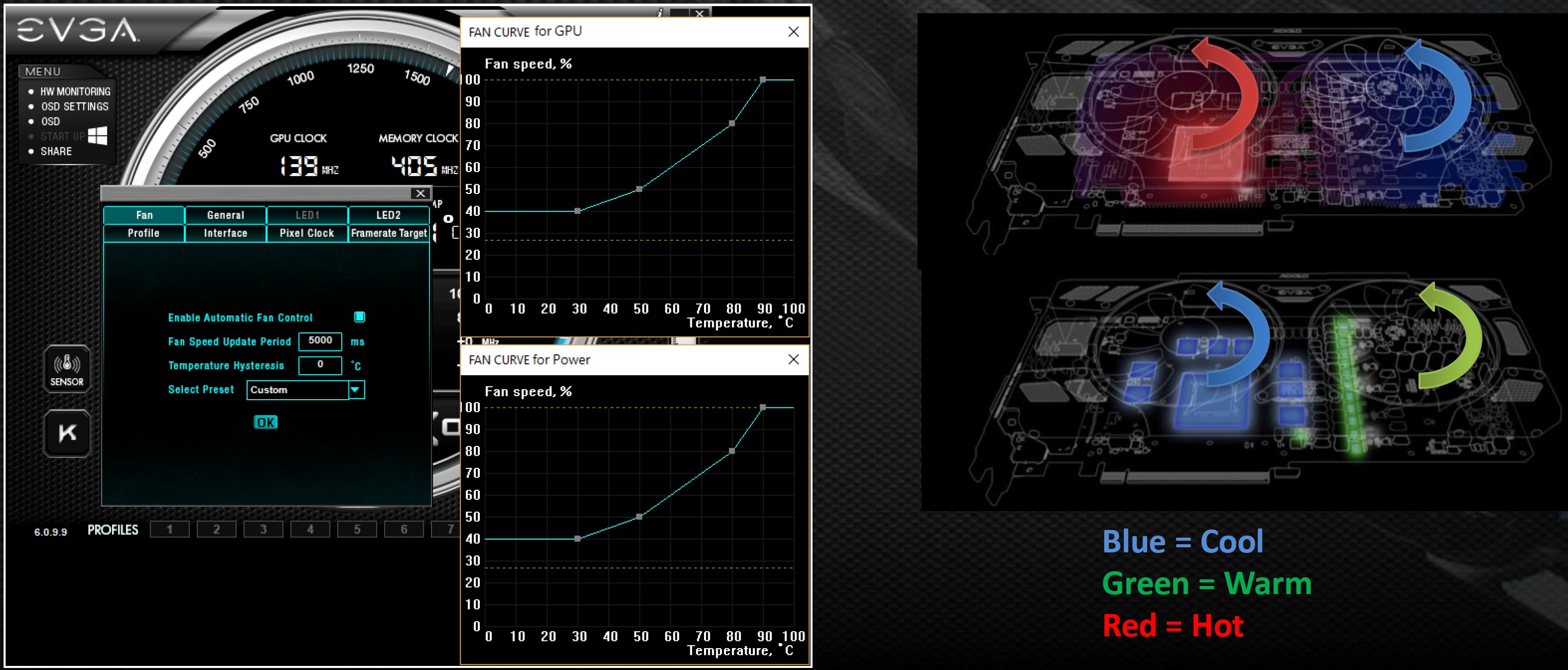
Be that as it may, this functionality serves as the foundation for a first for EVGA: asynchronous fan control based on real measured data, enabling separate curves for each of the two fans.
The assignment of sensors to the corresponding fans seems a little illogical, though. The RAM sits almost entirely under the left fan. According to EVGA’s slide deck, however, the readings from those sensors are supposed to affect the right fan, which is above the voltage regulator.
This bears out in practice. The actual hot-spot is observed on memory module M7 (the same place we found on the GTX 1080 FTW, incidentally). After removing the backplate, the right fan turns faster because the RAM is hotter than the VRM. We have already informed EVGA about this behavior.
EVGA developed on a very effective solution to capture sensor values in near-real-time using Sonix’s eight-bit flash-type microcontroller.
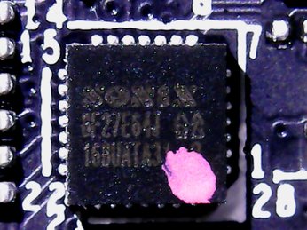
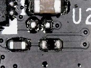
In addition to the sensors directly next to the MOSFETs in the above-right picture, sensors are also found below the GPU package (bottom-left) and near the memory modules (bottom-right).
Get Tom's Hardware's best news and in-depth reviews, straight to your inbox.
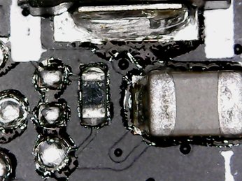
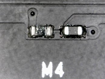
All of the data generated by these sensors can only be read by EVGA’s proprietary software, not surprisingly.
The Cooler: An Old Friend Made New
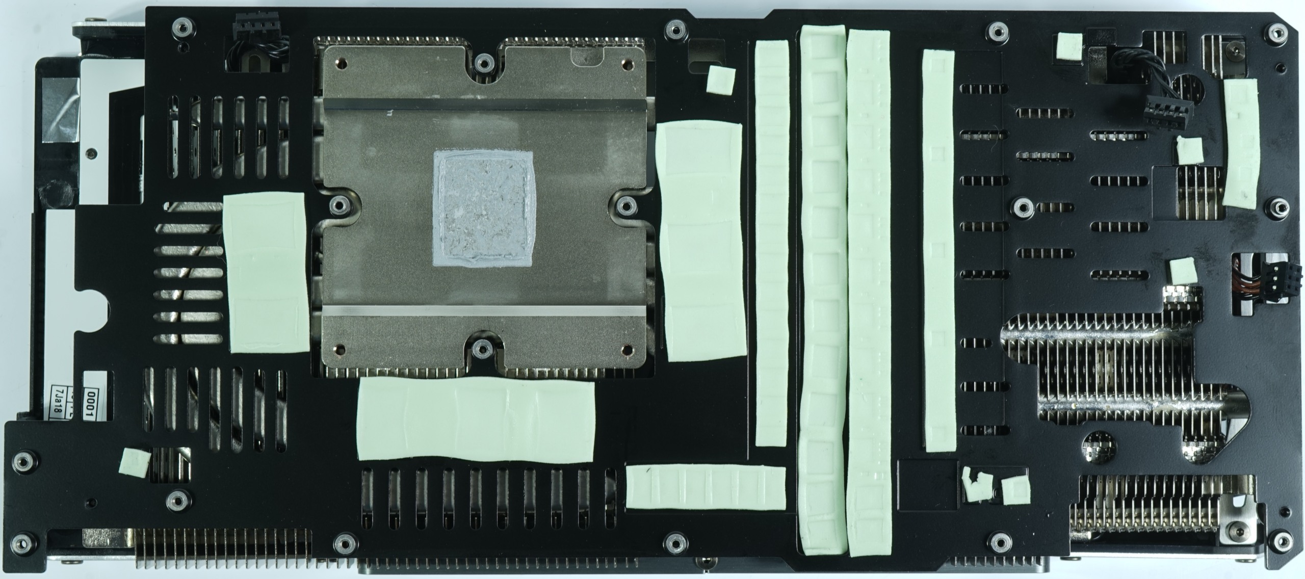
Before diving into our measurements, we wanted to disassemble the cooler. Although EVGA permits removing its thermal solution without voiding the card’s warranty, you have to use the right tool. As with the ACX cooler, iCX is based on the well-known sandwich principle, whereby a heat sink above the circuit board cools the memory modules and voltage regulator. In turn, this sink holds the large fins and contributes to the assembly’s stability.
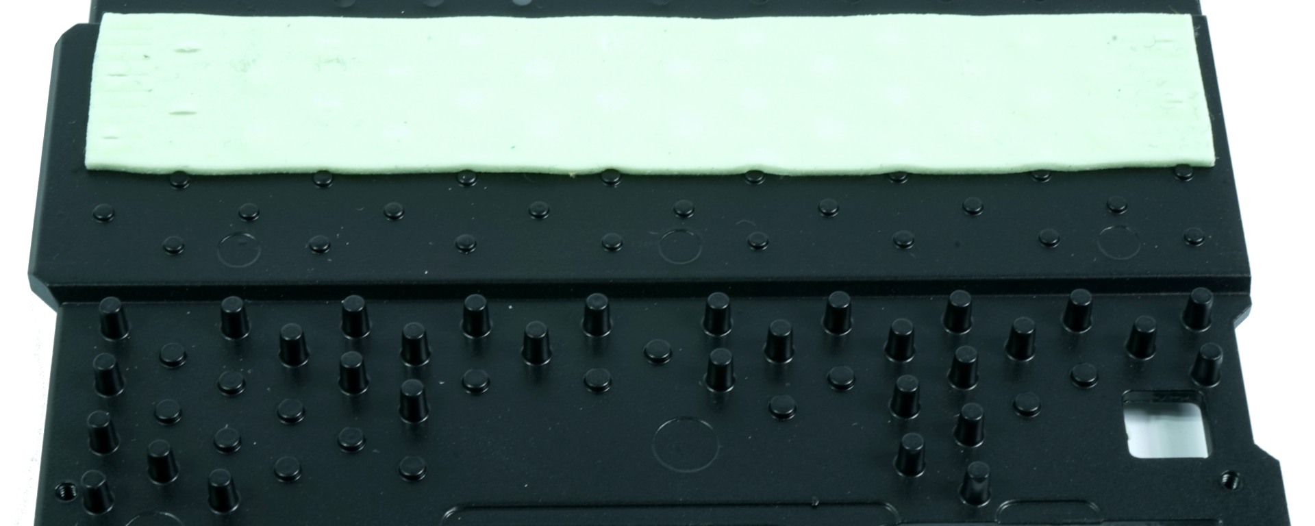
Certain parts of the cooling and mounting plate are peppered with small pins that protrude and increase the surface area. We’re a little skeptical of this approach’s usefulness; surely grooves would have been more effective.
The complete heat sink, which carries the fan modules, the fan shroud, and the LED backlighting, is then placed on this plate.
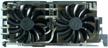
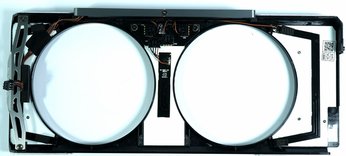
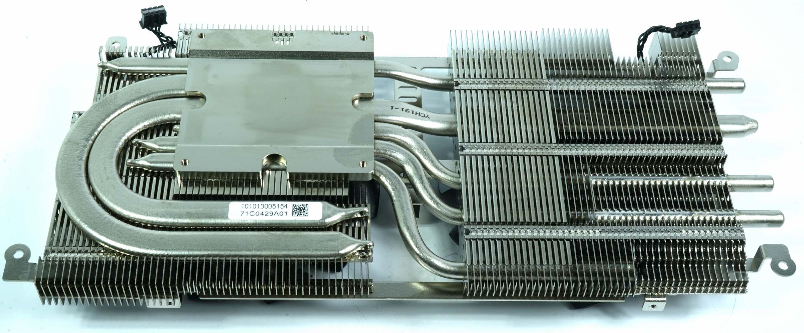
A nickel-plated heat sink on the GPU transfers waste heat to a short and a continuous two 8mm heat pipes, as well as to four 6mm pipes.
The vertically-oriented fins are bent in an I-shape, which EVGA says improves cooling performance. Frankly, we would have liked to see a larger radiator with integrated sinks to draw heat away from the memory, VRMs, and coils instead of the new sandwich solution.
Current page: Cooler Design And Technical Implementation
Prev Page EVGA GeForce GTX 1080 FTW2 With iCX Next Page Power Consumption And Cooling Performance
Igor Wallossek wrote a wide variety of hardware articles for Tom's Hardware, with a strong focus on technical analysis and in-depth reviews. His contributions have spanned a broad spectrum of PC components, including GPUs, CPUs, workstations, and PC builds. His insightful articles provide readers with detailed knowledge to make informed decisions in the ever-evolving tech landscape
-
FormatC Very similar to the AVX after thermal mod and BIOS flash. And as I wrote: generally a little bit better :)Reply
No idea, were are all the previous posts. Horrible tech... -
redgarl My first 1080 GTX FTW exploded. These cards were having huge issues due to the cooler.Reply -
FormatC I don't think, that any card can explode if you use it in a normal case with a good PSU. Normally ;)Reply
The main problem is every time the cooler philosophy. You can see three main solutions on the market:
Most used cooler types:
(1) Sandwich (like EVGA or MSI) with a large cooling plate/frame between PCB and cooler with tons of thick thermal pads
(2) Cooler only and a separate VRM cooler below the main cooler, memory mostly cooled over the heatsink
(3) Integrated real heatsink for VRM/coils and larger CPU heatsink/frame for direct memory cooling (Gigabyte, Palit, Zotac, Galax etc.)
I'm investigating this things since years and visited a lot of factories in Asia and the HQs of the bigger manufacturers. I have contact to a lot of R&D guys of this companies and we exchanged/ discussed my data over a long time. I remember, that I was sitting with the PM and R&D from Brand G in Taipei to discuss the first coolers of Type 3 in 2013 and it was good to see, how the R&D was following my suggestions:
This were the first coolers with integrated heatsinks for VRM and memory. Later it was improved to include the coils into this concept. The problem was at the begin the stability of the heavy cards and they moved to backplates. I was also in discussion with a few companies to use this backplates not only for marketing or stabilization but also for cooling. One of the first cards with thermal pads between PCB and backplate was the R9 380X Nitro from Sapphire. Other companies copied this and the cards with the biggest amount of thermal pads are now the FTW with thermal mod and the FTW2. I reported the issues to EVGA in early August 2016 and we had to wait over 3 months to see the suggested solution on the market.
One of the the problems is based on the splitted development/production process. The PBCs are mostly designed/produced from/together with a few big, specialized OEMs. But nobody is proceeding a simulation to detect possible thermal hotspots (design dependend) first. The cooler industry works also totally separately and the data exchange is simply worse. Mostly they are using (or get) only the main info about dimensions of the PCB, holes and component positions (especially height) and nothing else. This may work if you lucky, but the chance is 50:50. Other things, like a strictly cost-down and useless discussions about a few washers or screws (yes, it's not a joke!) will produce even more possible issues. Companies like EVGA are totally fabless and it is a very hard job to keep all this OEMs and third-party vendors on a common line. Especially the communication between the different OEMs is mostly too bad or not existing.
Another problem is the equipment and the utilization in the R&Ds. If I see pseudo-thermal cams (in truth it are mostly cheap pyrometers with a fake graphical output and not real bolometers) and how the guys are using it (wrong angle and distance, wrong or no emissive factor, no calibrated paintings) I'm not surprised, what happens each day. Heat is a real bitch and the density their terrible sister. :D
For all people, interested in development and production of VGA cards:
I collected over the years a lot of material and pictures/videos from inside the factories and write now, step-by-step, an article about this industry, their projects, prototypes and biggest fails. But I have to wait for all permissions, because a few things are/were secret (yet) or it was prohibited to use it public. But I think that's worth to be published at the right moment:)
-
FormatC The MX-2 ist totally outdated and the performance is really worse in direct comparison with current mid-class products. The long-term stability is also nothing to believe (on a VGA card). The problem of too thick thermal grease to compensate some bigger gaps (instead of pads) is the dry-out-problem. The paste will be thinner and lose the contact to the component or heatsink. The sense of such products is to have a very thin film between heatsink and heatpreader/die in combination with a higher pressure.Reply
I tested over the weekend the OC stablity of the memory modules. If I use the original ACX 3.0 or the iCX, I get not more than 100-150 MHz stable (tested with heavy scientific workloads). With a water block I was able to OC the same modules up to 300 MHz more and got no errors - with a big headroom. I write not about gaming, some games are running with much higher memory clocks. But this isn't really stable. It only seems so. But this is nothing to work with it. :) -
FormatC Gelid GC Extreme or Thermal Grizzly Kryonaut. A lot better and not bad for long-term projects. The Gelid must be warmed up a little bit, it's more comfortable without experience. :)Reply -
FormatC Too dangerous without experience and not so much better. And it is nearly impossible to clean it later without issues.Reply -
Martell1977 I've used Arctic MX-4 on several CPU's, GPU's and in laptops. In fact I just used some last night in a laptop that was hitting 100c under load. I put some of the MX-4 on th CPU and both sides of the thermal pad that was on the GPU and the system runs at 58c under load now.Reply -
FormatC The MX-2 is entry level, the MX-4 mid-class but both were developed years ago. The best bang for the buck is the Gelid GC Extreme (a lot of overclockers like it) but the handling is not so easy. The Kryonaut is a fresh high-performance product and easier to use (more liquid). You have only a short Burn-In time and the performance is perfect from the begin. The older arctic products are simply outdated but good enough for cheaper CPUs. Nothing for VGA.Reply
I tested it a few weeks ago, also here (how to improve VGA cooling):
