Transient Response

Upon transient application, the output voltage dips by approximately 100mV and the regulator needs a respectable two milliseconds to compensate. But when the transient gets removed, output shoots up by 150mV or so and needs at least five milliseconds to settle back down. That's about right for switching regulators with primary-side sensing that iteratively adjust based on the previous cycle’s feedback (as opposed to opto-isolators, which provide continuous proportional feedback).
Short-Circuit Response

What happens under an output short-circuit condition? Exactly what you'd expect: the flyback converter tries to drive the output as hard as it can, and once it detects that the voltage isn’t coming back up, it shuts down for a little while. Here, the controller needs approximately 17ms to call it quits, taking a one-second break between restart attempts.
Isolation Withstand Test, Part One

Based on past experience, a clean board with smooth copper traces can withstand as much as 2kV down to 0.5mm of creepage distance, which is more than what 1kV ceramic capacitors tend to fail at. Here, the minimum creepage is closer to double that amount, and the lack of solder mask makes it easy to tell the board is clean along its border. Since the transformers we've looked at so far have all made it past 2kV, the non-Y capacitor should be the weakest link.
Article continues belowPredictably enough, that’s exactly what happened at 1300V.
Dead Cap

As is often the case with ceramic capacitors that have failed from a limited energy over-voltage, there is no way to tell when one is bad without actually testing them for withstand voltage. It typically takes tens of volts before the internal faults becomes conductive.
I let this capacitor stew for several seconds at 10mA (~3W), and it still shows no sign of overheating. If I really wanted to blow one of these up, I would need to crank both voltage and current up a notch by borrowing an old microwave oven’s transformer.
Isolation Withstand Test, Part Two

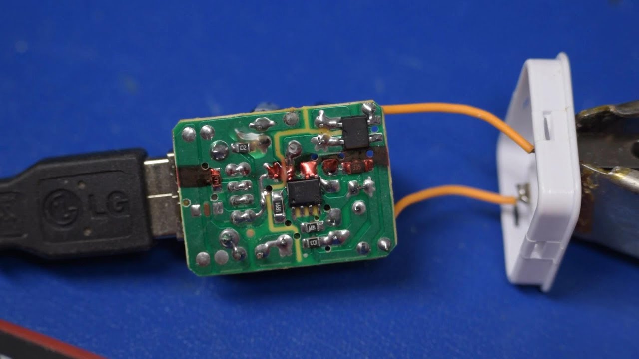
Again, as predicted, the second thing to fail is creepage across the board's primary and secondary boundary, from the corner of an SMD resistor pad on the primary side to a solder blob on the secondary side.
Track Close-Up

While the arc may have started between the slight copper point near the mid-right and the solder blob tip on the left, most of the charring is concentrated along the hole’s edge.
Since the edge of a hole has less specific heat to help it cope with thermal dissipation, the arc burnt itself a path across the separation and managed to creep most of the way across the hole from where it started. As old material smoldered and sputtered off, it enabled new and more effective paths to get charred into existence.
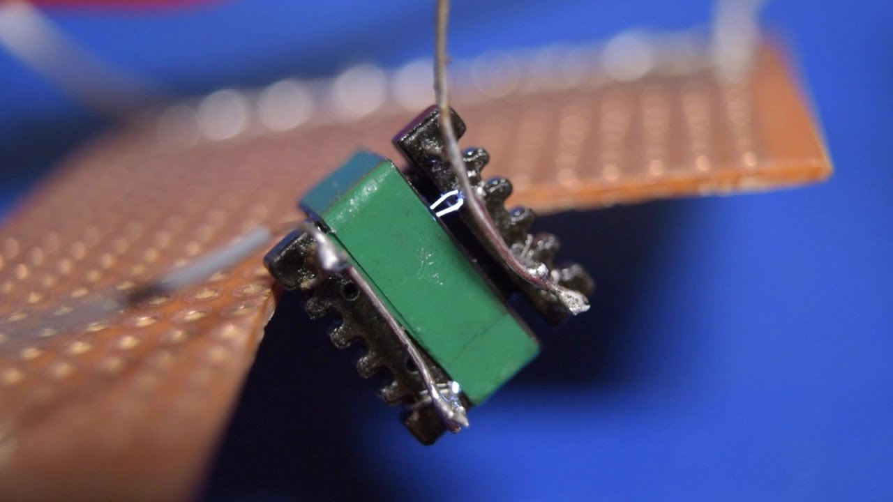
Transformer Close-Up

There is only one thing left to test to destruction: the transformer, which is also the most critical safety component. How far short of 3500VAC will it fail? What sorts of ugly secrets (aside from the lack of double-insulation) lie within?
I was really hoping for an arc fault between those two crossed wires. Is it wrong to be disappointed when something fails to fail?
Isolation Withstand Test, Part Three

At first, it arced from pins and jumper wires to the ferrite core at around 2800V. That would have been okay if the board had a proper spark gap to prevent such a voltage difference from building up between sides. Then it went quiet. So now we now have an internal arc to investigate. What sort of horror are we going to dig out of it?
Transformer Autopsy

As far as transformer windings go, this is one of the worst possible cases imaginable, aside from an outright short between primary and secondary straight from the factory. Right under the top tape layer, the thin wire feedback winding sits directly on top of the much heavier-gauge output winding with nothing more than the wires’ coating separating them. All of the favorable conditions for a primary-to-secondary short are here.
I would not have expected the transformer to make it to 2800V like this.
Full-Contact Weave

On the winding side opposite the previous image, the wiring is partially covered in a hard varnish or lacquer, and the feedback winding can be seen going over and between output winding turns.
While lacquering or varnishing windings can be used as an alternative to tape, this only works when windings are wound, fully varnished, and cured before the next winding is wound on top of it, not as a patchy job after everything has already been wound on the core.