







Self-destructing graphics cards: Why are power connectors melting, and what can you do about it?
12VHPWR and 12V-2x6 power connectors are still melting and taking graphics cards with them.
If you own a recent graphics card, perhaps one of the best graphics cards, with a 12VHPWR or the latest 12V-2x6 power connector, you're probably aware of the many stories of these plugs melting. You may be wondering what you can do to protect your own GPU from an expensive failure.

Unfortunately, because of design choices baked into this connector standard and the way it’s implemented on graphics cards, it’s difficult, if not impossible, to guarantee that your GPU is 100% safe from becoming a melted mess. We dug into why this is happening to help you understand your exposure to this risk and some steps you can take to keep your card safer.
The primary reasons for this persistent risk of failure are related to design choices outside of our control. The biggest issue, of course, is that the total rated power draw of today’s highest-end graphics cards, like the GeForce RTX 5090, has climbed right up to the 600W limit of what the 12V-2x6 connector is rated to carry for extended periods.
According to this analysis, each pin in the 12V-2x6 connector is operating with a minimal safety factor when carrying that much current. If anything does go wrong in a PC's power delivery path when an RTX 4090 or RTX 5090 is running all-out, the low safety factor of this connector at its limits means that any one wire in the cable is more likely to end up carrying more current than it's rated for or even physically able to, and that means a greater risk of catastrophic failure like overheating, melting, or fire, which would destroy your graphics card.
In contrast, the six- and eight-pin PCIe connectors we’ve used for years offer such large safety factors that it would be extremely difficult to create a situation where one would be at risk of melting down. Indeed, I can’t recall a single instance where one of these older connectors suffered a failure due to an overload in typical use.
Less power-hungry cards like the RTX 4080, RTX 5080, and below either have board power ratings well within the 600W maximum of the 12V-2x6 connector, or they use the older six-pin or eight-pin connectors. Simply due to their lower power draw, these cards are less likely to experience catastrophic failures.
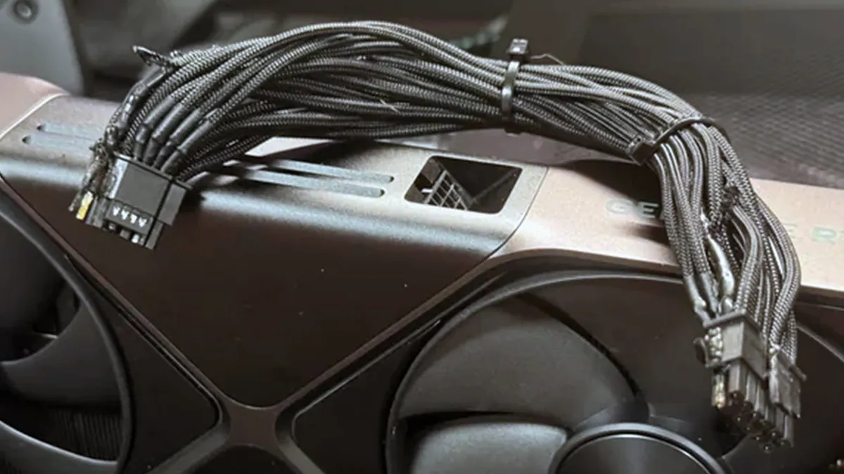
Beyond the physical limits of the connector itself, the power-delivery designs of graphics cards have also changed in a way that can decrease safety. As explained by extreme overclocker and power-delivery guru Buildzoid, graphics card board designs have been simplified over time to reduce cost and complexity, but those same changes have removed the ability for a graphics card to actively balance its current draw in order to maintain safe operation in the event of a failure.
Get Tom's Hardware's best news and in-depth reviews, straight to your inbox.
Because recent graphics cards that use this connector, like the RTX 4090 and RTX 5090, are only aware of the state of the overall 12V signal rather than including circuitry that monitors and rebalances the current on each 12V pin, a failed cable or poor contact on this connector won't be detected or mitigated by the graphics card. That coarse monitoring and management is by design, and it's not something you can fix.

It's rare to see the 12V-2x6 connector on AMD graphics cards, but it has been used on designs like the Sapphire RX 9070 XT Nitro+. Buildzoid notes that Sapphire's 12V-2x6 implementation lacks any kind of current balancing or monitoring circuitry, just as we see on some RTX 40-series and RTX 50-series board designs. This RX 9070 XT only comes rated for 330W of total board power, though, so a catastrophic failure at the power connector or its cabling is less likely.
Not every graphics card today is built with such coarse power monitoring. We found that ASUS' ROG Astral RTX 5090 32GB cards do mitigate these risks to some degree by implementing a more sophisticated monitoring circuit at the power connector. If you’re using Asus’ GPU Tweak software, this circuitry will warn you if it detects an imbalance so you can check the connection. Even so, Buildzoid warns that circuit design can only alert the user that a current imbalance exists, not actively rebalance load across the individual pins to avoid failures.
How to lower your risk of a melted cable or connector
If you're purchasing a GPU with a total board power that approaches the 600W maximum sustained power that the 12V-2x6 connector is rated for, and that card also doesn't implement a fine-grained current monitoring or balancing solution in its board design, there's only so much you can do to protect your system and your card. There are a few common-sense steps you can take, though.
The first is to be aware of how much power your GPU will draw when choosing your components, and to plan accordingly. Make sure every part of your power delivery setup is properly rated and of the highest quality it can be.
Choose only a high-end, high-wattage power supply from a reputable vendor that's more likely to include heavy-duty cabling, properly tuned overcurrent and overvoltage protections, and wattage ratings on the 12V rail or rails that are more likely to be trustworthy. It's never wise to skimp on your power supply, but it would be especially foolish to cheap out when you're looking at a top-end graphics card like an RTX 4090 or RTX 5090.

If you're thinking of carrying over a PSU from an older build or using the one in your existing system, you might also put that older unit on your shelf as a backup and buy a new one to go with your new graphics card. Power supply performance does degrade with age, and your older unit might not be able to deliver its rated performance any longer.
A new PSU that conforms to the latest ATX 3.0 or ATX 3.1 standards is also more likely to have been designed with the demands of the latest components in mind. Check out our list of the best PSUs to help you in your search.
When you build your PC or install a new graphics card in an existing system, take utmost care that you're fully inserting the power connector at both ends. Be extra careful with your cable routing to ensure that neither end of the cable is placed under any kind of strain that would result in poor contact.
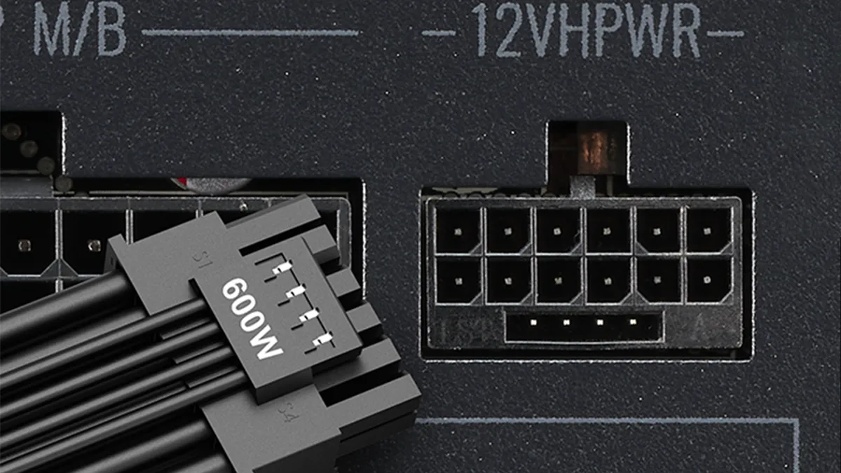
Seasonic, for example, suggests that users not introduce any bends or strains in the 12V-2x6 cable any closer than 35mm from the connector. Given the massive size of many RTX 5090 graphics cards, you might find that you have less clearance between the side of the GPU and the side panel of your case than you expect, so be careful and measure clearance yourself.
If it's not possible to avoid such strain at either end with your existing parts, you might consider a high-quality 90° cable that gives you more routing flexibility. You might even need to swap out your entire case for one with more clearance and a more accommodating cable-routing path. Check out our list of the best PC cases for suggestions.
Given that some investigations of this issue have shown changes in current balancing across individual supply wires after 12VHPWR or 12V2x6 cables are unplugged and then replugged, you could be extra cautious and perform only one mating and unmating cycle of this cable type at either end before discarding it and using another. If you do need to replace your cable, make sure that you're purchasing a compatible replacement directly from your PSU's manufacturer or that any third-party cable you purchase is from a reputable supplier.

Finally, you might add a third-party hardware monitoring tool, like Thermal Grizzly’s Wireview Pro or the upcoming Wireview Pro 2, to your system. These tools give you fine-grained, in-depth monitoring capabilities on the 12V-2x6 connector, like current draw and temperature, on a per-pin basis.
If something does go wrong, these tools can sound an alarm to let you act before a catastrophic failure occurs. It’s worth noting that these tools add another potential point of failure in your power delivery path, remote as that risk may be. You can also take advantage of community-developed solutions that monitor connector temperatures and warn of overheating.
To banish this risk forever, it appears that the industry heavyweights that comprise the PCI Special Interest Group (or PCI-SIG) are going to have to create an even more robust version of the 12V-2x6 specification with a higher safety factor than the spec includes today. We look forward to the day when PC builders won’t have to worry about the risk of melting connectors or overheating wires when they fire up a game on a high-end GPU. Until then, if you have one of these connectors on your graphics card, it’s worth being extra cautious with your PC’s power delivery setup, all the way from the PSU to its cabling to the GPU.

As the Senior Analyst, Graphics at Tom's Hardware, Jeff Kampman covers everything that has to do with graphics cards, gaming performance, and more. From integrated graphics processors to discrete graphics cards to the hyperscale installations powering our AI future, if it's got a GPU in it, Jeff is on it.
-
Loadedaxe Reply
I agree, even if it is sarcasm..I think we are headed there, PC gaming has just become way to expensive.Notton said:Ditch desktop PC gaming, switch to a PS5 or Steamdeck/handheld PC. Problem solved. -
ezst036 There are limited options. According to this image from this Toms' article: https://www.tomshardware.com/pc-components/gpus/nvidias-rtx-5090-power-cables-may-be-doomed-to-burnReply
https://cdn.mos.cms.futurecdn.net/MJzPaCkPWQSKV8xTRmHUsj-970-80.png.webp
1) An Astral RTX5090 is according to rumors properly shunted and will not melt down at the connector. So that is an option. (also mentioned in the article)
2) An RTX 4090 Matrix also will not have a connector melt down.
3) Any RTX 3090/80/70 was safe, Nvidia set them all up properly from the information I have
4) Any AMD or Intel video card. It had to be listed.
It would really be nice as well as a good service for Tom's Hardware readers if Tom's Hardware would sniff out any and all Nvidia video cards anywhere and list the ones where the provider went above and beyond to protect the card. Such as the Astral and Matrix lines. A spreadsheet would be by far the best service Tom's could provide. Perhaps a html table if it has to be that way.
I would like to get actual confirmation of these things. I find it a little hard to believe that the Astral and the Matrix are the only two options of the newer generations that a buyer can have confidence in. There have to be at least a handful of others out there among the sea of those who will melt the connector at any time. -
hotaru251 Reply
idk if I would say "flawed" but i'd for sure use poorly implemented.logainofhades said:The design is flawed.
The thing afaik hasnt ever damaged a mid/low end gpu using it..just the 90 & 80 tier.
which is likely issue of the user error risk w/ its very littel tolerance on bending coupled w/ the fact nvidia reduced safety on gpu end that would prevent a cable/gpu from being too hot and melting the plastic. (as back on 3090 they had actual safety built in)
but yeah honestly there should of been a lawsuit over it given how widely known an issue it is and them doubleing down on it with 50 series. -
milleron Undervolting the 4090 has been recommended to prevent frequency throttling. I did undervolt my 4090 from the "get-go." I do have a Thermal Grizzly WireView installed between the cable and my 4090. While using it for MS Flight Simulator, I've never seen any wattage even close to 600. Is there any suggestion, theoretical or practical, that undervolting the 600w GPUs can make melted components less likely?Reply -
Eximo Well, yes, less power should mean less potential for overheating the wires.Reply
The main issue is unbalanced current flow though. So nothing says that at 400W a single wire won't take too much current and melt anyway. It comes down to the pin interface mostly it seems. Wear and tear of multiple insertions is a factor, as well as how much bending is needed to fit it in some chassis. -
Why_Me It's a Darwin thing imo. Those gpu's separate the people who have a PC IQ north of a turnip from the people who should stick to consoles and pre builts.Reply
Don't stick those cards inside a crackerbox size case, use a proper psu and make sure you have a solid connection. -
John Nemesh Reply
Came here to say exactly this. Plenty of good cards out there that don't use this defective standard!logainofhades said:Don't buy a GPU with said connector, problem solved. The design is flawed. -
chaz_music I have commented on this topic nearly a dozen times. I am a power electronic engineer who has worked on systems up to 12MW in size and currents up to 6300A. So I easily understand this kind of application. It is very evident that someone inexperienced has decided on this configuration without consulting the connector company on how to derate the pin current and how to implement this reliability. And then there is marketing specmanship that you find in the connector datasheets themselves.Reply
I would have selected an Anderson connector or something similar. Paralleling DC power pins is a dangerous thing to do, especially in light of the complex physics. If they are Hell bent on sticking with this configuration on the GPUs, they should be using interleaved PWM switching stages, with one power stage used per pin. This allows the PWM controller to force each pin to draw a balanced load and not rely on uncontrolled path resistances. These resistances are for example: connector pins, wire crimp, and wire - on both ends of the cabling system. So the imbalance can occur at the GPU side and the PSU side.
The 9A current derating quoted in the article seems high. When I looked at the Minifit application notes for similar parts, I saw that it showed a derating to 5A (or was it 5.5A?) for a 16 way housing. That is 8 pins bringing power into the GPU, and 8 pins taking power out (return). So for the current coming into the GPU I get:
I (total) = 8 pins x 5.5A per pin = 44A
I would expect the voltage to droop badly with this much loading on the PSU and cabling so for a 600W load the voltage could easily be around 11.75V or even lower. The GPU will pull what it needs regardless. So 600W / 11.75V = 51A.
Connector systems are all about power dissipation, cooling, and material heat capability. Most UL approved nylon housings are 94V0 which will tend to not flame up and self extinguish when the heat is stopped. This nylon is usually rated for 105 Deg C at the housing.
The connector industry is not very transparent on what assumptions they used for the datasheet, and where the alligators exist in the usage. So for the datasheet info they will take a brand new pin and socket, crimp on a freshly stripped wire, and plug the entire assembly together and make measurements. The connector system is almost never this pristine the rest of its existence. Was the PSU or interface cabling made in Asia and sent by boat? It will suffer from humidity and corrosion. This is a double hit if it was shipped in the summertime. Accelerated failure modes due to higher heat.
And the datasheets are expecting decent wire cooling to draw heat away from the connector housing, i.e., no "pretty" nylon shroud covering the wiring to allow for reasonable convection cooling of the wire. The wire is expected to act as a heatsink for the connector pins and sockets.
Here are some suggestions to help people with this issue - but this is offered as unpaid assistance. In some states they say "buyer beware". But these should help:
1. Do not use cabling that has a wiring loom wrapped around it, which acts as to reduce and constrict the airflow. The datasheets are expecting decent wire cooling to draw heat away from the connector housing, i.e., no "pretty" nylon shroud covering the wiring to allow for reasonable convection cooling of the wire. If this loom exists, remove it and allow the wire insulation to convection cool better. The wiring looms should require yet another current derating if you want to use them.
2. The wire is expected to act as a heatsink for the connector pins and sockets. Again this is simple physics. The pin and socket contact points are tiny and much smaller than the wire cross-sectional area. For this reason, suppliers should find a way to use larger wire than is presently being used.
3. Since the pin and socket contact points have gone through oxidation and corrosion before you even install them, you should plug and unplug them several time to knock this oxidation off. Don't get excessive with it because you don't want to create fretting failure by scrapping off too much tin plating. About 3-5 time is great. Make sure the last pass is seated well.
4. You want to get the heat out of the cabling ends. So mount a fast fan by the GPU connector, as well as at the PSU connector. The imbalance can occur at both ends!
I hope these suggestions help people while the industry addresses these shortcomings.