Tom's Hardware Verdict
A solid and dependable design backed up with great software support. If you want to build your own RP2040 powered device, and don’t want the hassle of wiring the bare chip, this is for you.
Pros
- +
+ Small form factor
- +
+ GPIO selection is excellent
- +
+ PCB Design footprints
- +
+ Ease of use
Cons
- -
2mm pin pitch
Why you can trust Tom's Hardware
We’ve seen the Raspberry Pi Pico in some rather interesting form factors. From Pimoroni’s Tiny 2040 to Adafruit’s Feather RP2040 via Arduino’s Nano RP2040 Connect, we’ve seen many of the best Raspberry Pi Pico boards cross our workbench. But Solder Party’s RP2040 Stamp is something a little different.
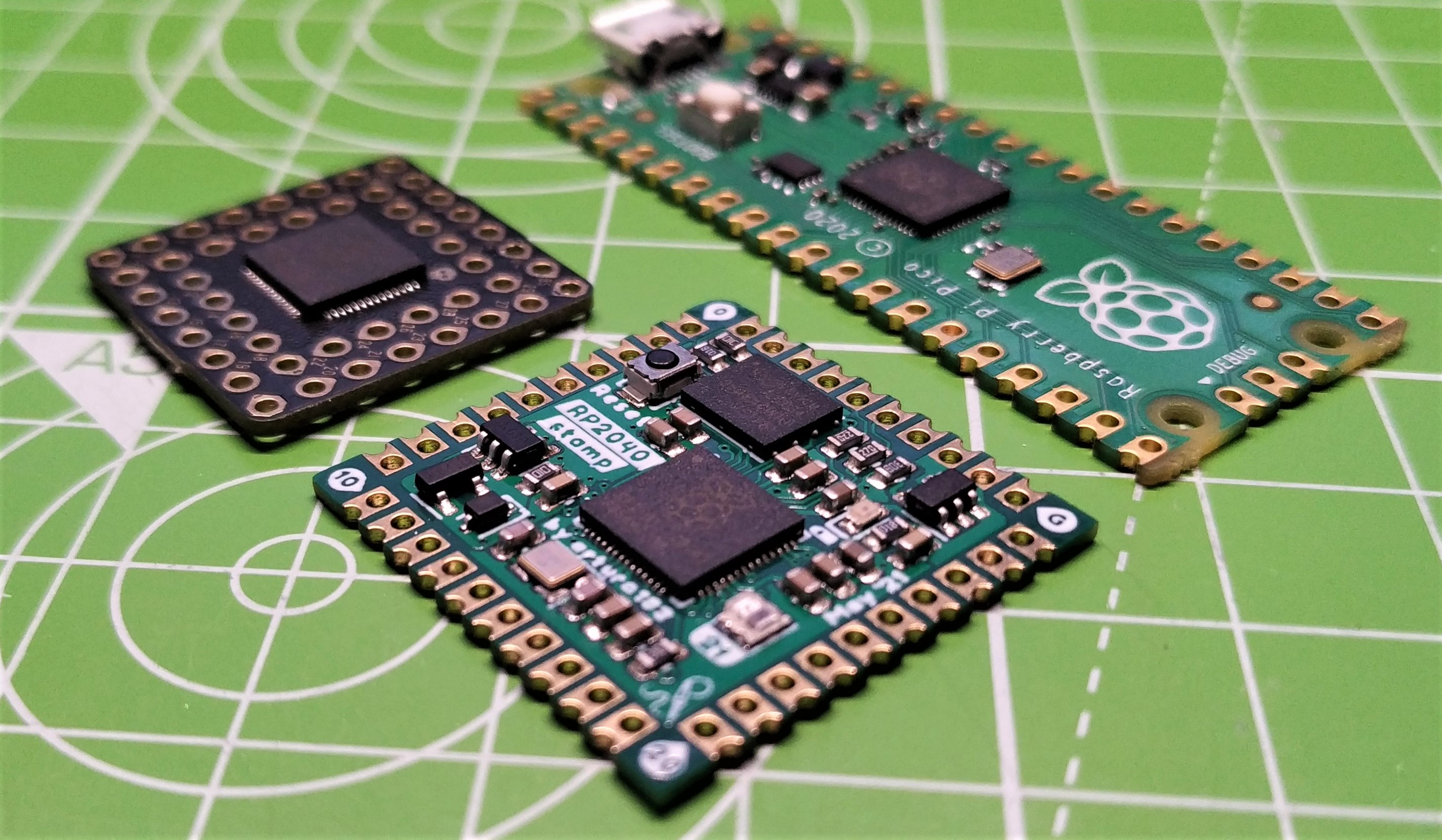
This $12, one-inch square board resembles a postage stamp but emblazoned on the center is the familiar RP2040 SoC, along with 8MB of flash storage and a full complement of GPIO pins forming a perimeter of castellations around the board.
Solder Party’s RP2040 Stamp is made for those of us that want the power of the RP2040 in our own custom PCB, but we don’t want the hassle of soldering small-pitch electronics. Drop this into your own custom robot, machine learning, computer vision project and you're good to go.
With that in mind we soldered our test unit to the $6.50 RP2040 Stamp carrier board, and settled down to an afternoon of tests with this rather curious board.
RP2040 Stamp Specifications
| System on Chip | RP2040 microcontroller |
| Dual-core Arm Cortex M0+ processor, flexible clock running up to 133 MHz. | |
| 264KB of SRAM, and 8MB of on-board Flash memory | |
| GPIO | All 30 GPIO pins |
| 16 x PWM | |
| 2 x UART | |
| 2 x SPI | |
| 2 x I2C | |
| 1 x WS2812B NeoPixel (GP21) | |
| LiPo supply and charging circuit | |
| USB breakout | |
| 500mA 3.3 LDO Low-Dropout Regulator | |
| SWD (Debug) Breakout | |
| GPIO pins have 2mm pitch | |
| Dimensions | 1 x 1 inch (25.4 x 25.4 mm) |
Using the RP2040 Stamp
The one inch squared form factor of the stamp, along with the castellations around the perimeter of the board mean that this board is destined to be used in a custom PCB. Something that Solder Party is keenly aware of and provides footprints for use with the popular PCB design applications. These footprints are for surface mount and through hole soldering.
The most basic way to connect your RP2040 Stamp to a custom PCB is by matching the footprint. This will line-up the RP2040 Stamp’s castellations with pads on your PCB, then using a blob of solder we can join the two together.
If you wish to use the RP2040 Stamp with a breadboard, things get a little tricky. The 2mm pitch favored by the board means that we can’t just drop this onto a breadboard. Sure we can buy 2mm pitch header pins and breadboards, but we have to factor this into our project costs. That said, 2mm pitch was the right way to go for our testing as it affords us all the GPIO pins present on the RP2040 and keeps the board small. The pins are logically laid out, starting at 0 and moving counterclockwise around the perimeter of the board.
Get Tom's Hardware's best news and in-depth reviews, straight to your inbox.
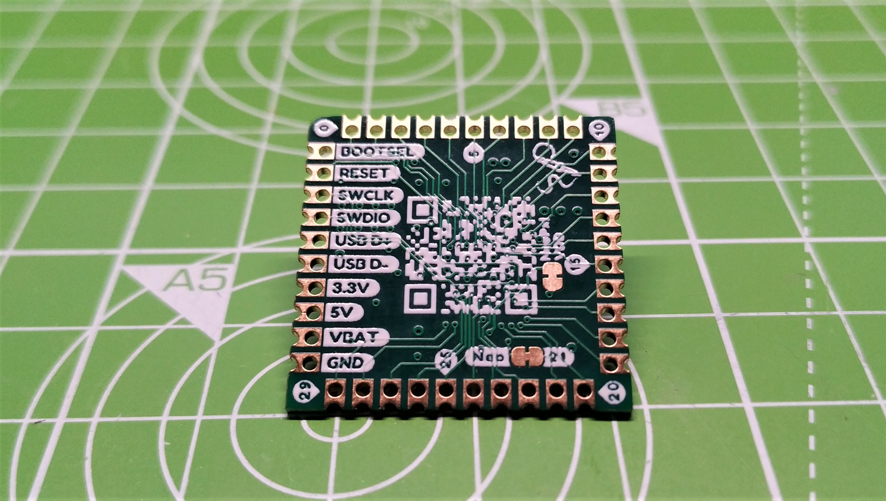
Speaking of GPIO pins, RP2040 Stamp has a few extras built in. On the underside of the board, we spotted breakouts for USB (D+ and D-), Battery and serial debug (SWCLK, SWDIO) which enables the board to work with the carrier board, but more importantly it enables it to work with your custom board. Clever stuff!
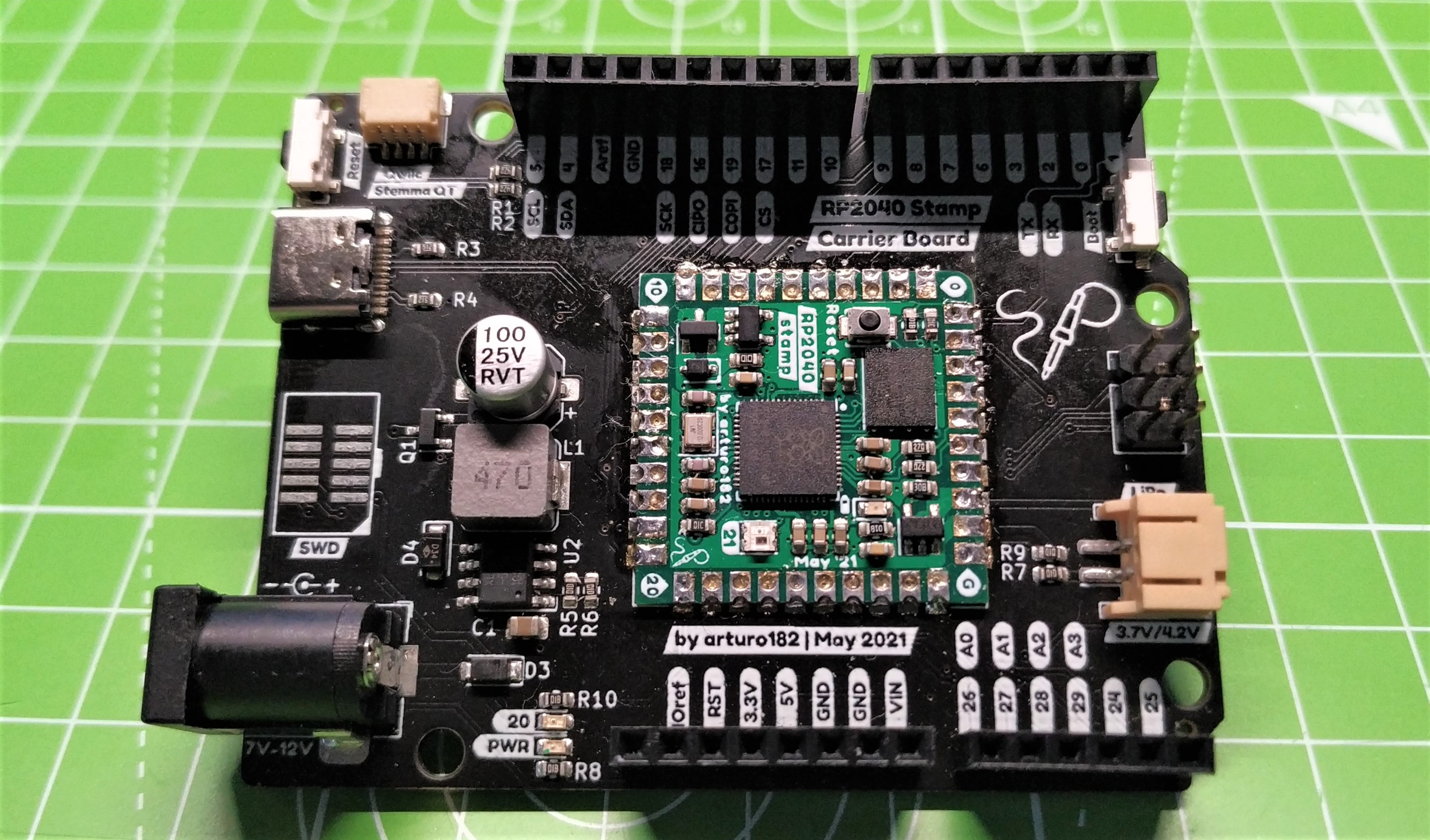
For our test we used the RP2040 Stamp Carrier Board, a board that bears a similarity to the Arduino Uno form factor and breaks out enough, but not all of the GPIO pins. Soldering the RP2040 Stamp to the carrier board was simple. We just had to make sure that we got the orientation correct before we started.
Once it was soldered, we connected the board to our machine via the USB-C port. It is great to see another board using USB-C. The connector is robust and practically foolproof. We updated to the latest version of CircuitPython, but as this is an RP2040, we can use one of many programming languages. For this review we are going to stick with CircuitPython as it provides the best means to access all of the board’s features. On the CircuitPython homepage there is a special version of CircuitPython for the RP2040 Stamp.
We started with the simple stuff. Could we blink the user LED, located just behind the DC power jack? The answer is of course yes. The user LED is connected to GP20 and it only took a moment to write a simple script to blink the LED 100 times with a 0.1 second delay.
This simple test confirms that our RP2040 Stamp is soldered correctly, and that we can communicate with it.
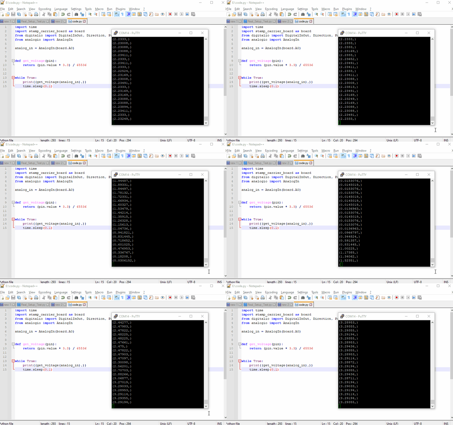
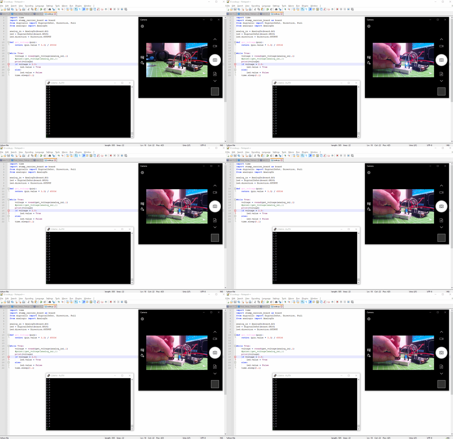
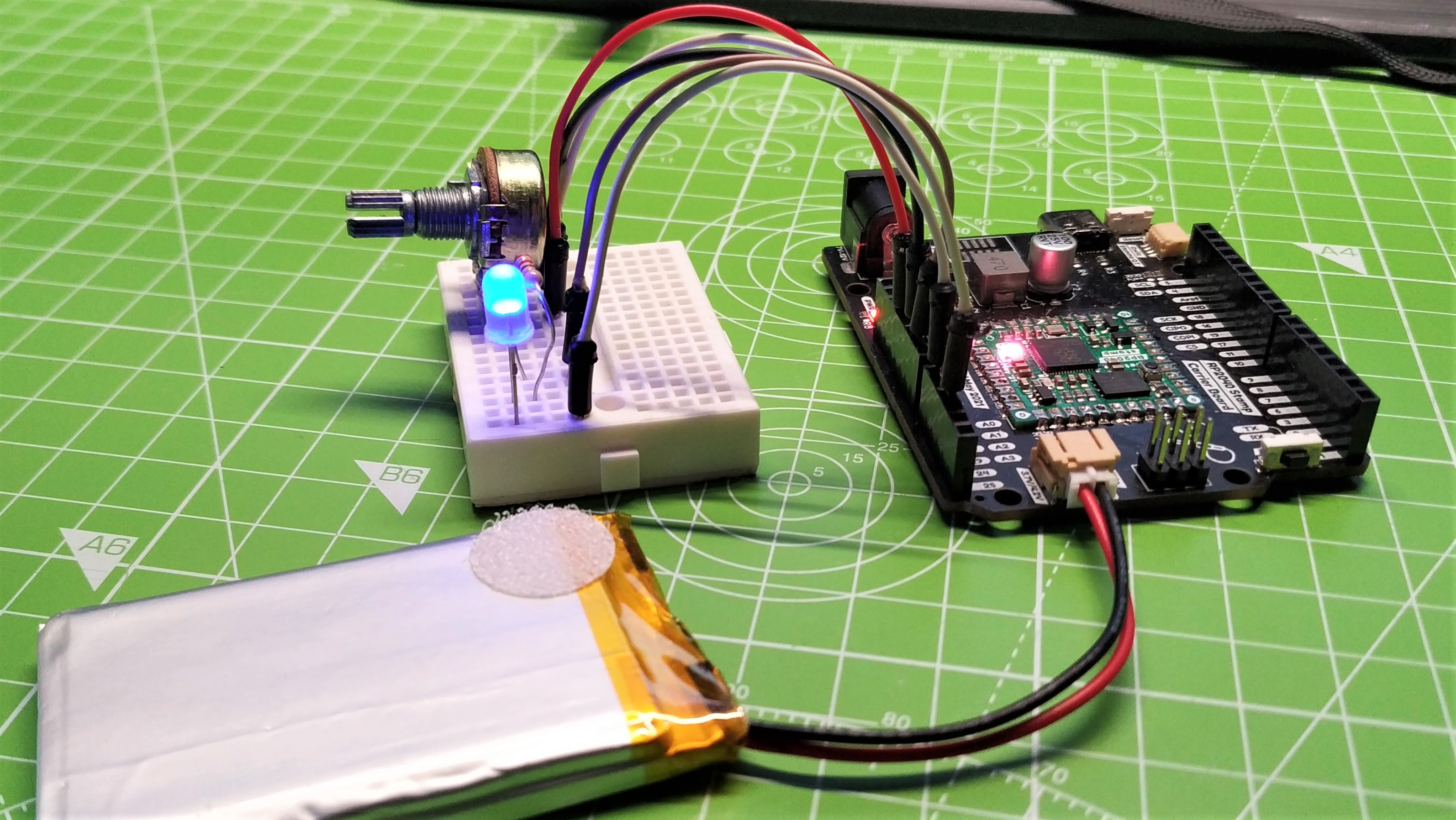
We performed two further tests. The first was an external LED connected to GP9 and then we added a 10K Ohm potentiometer and edited the code to use the potentiometer as a crude switch. The switch triggers the LED on / off based on the voltage read from Analog pin 0. This test also afforded us the opportunity to try out the carrier board’s 7 - 12V DC barrel jack with a 9V PP3 battery. It went perfectly and our code ran independently of a USB power supply and computer.
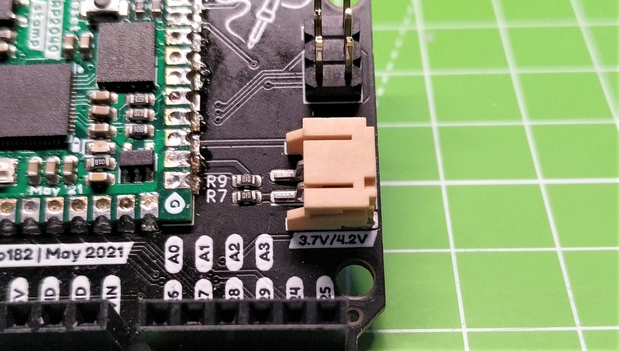
We also tested the carrier board’s onboard LiPo charging system, which provided a steady 600mA charge current to the 2000mAh battery. When the USB power source was removed the board kept on working, running from the LiPo.
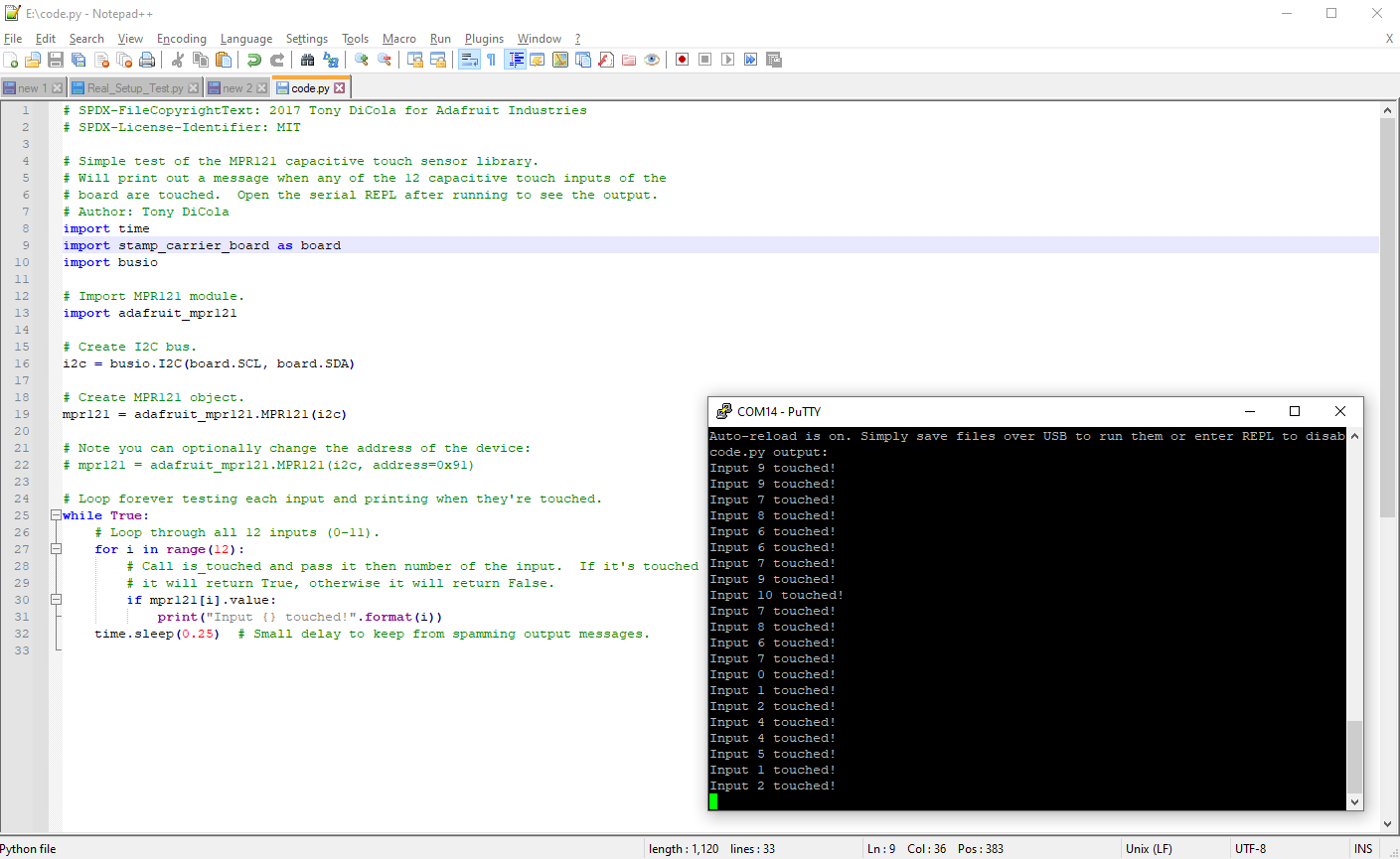
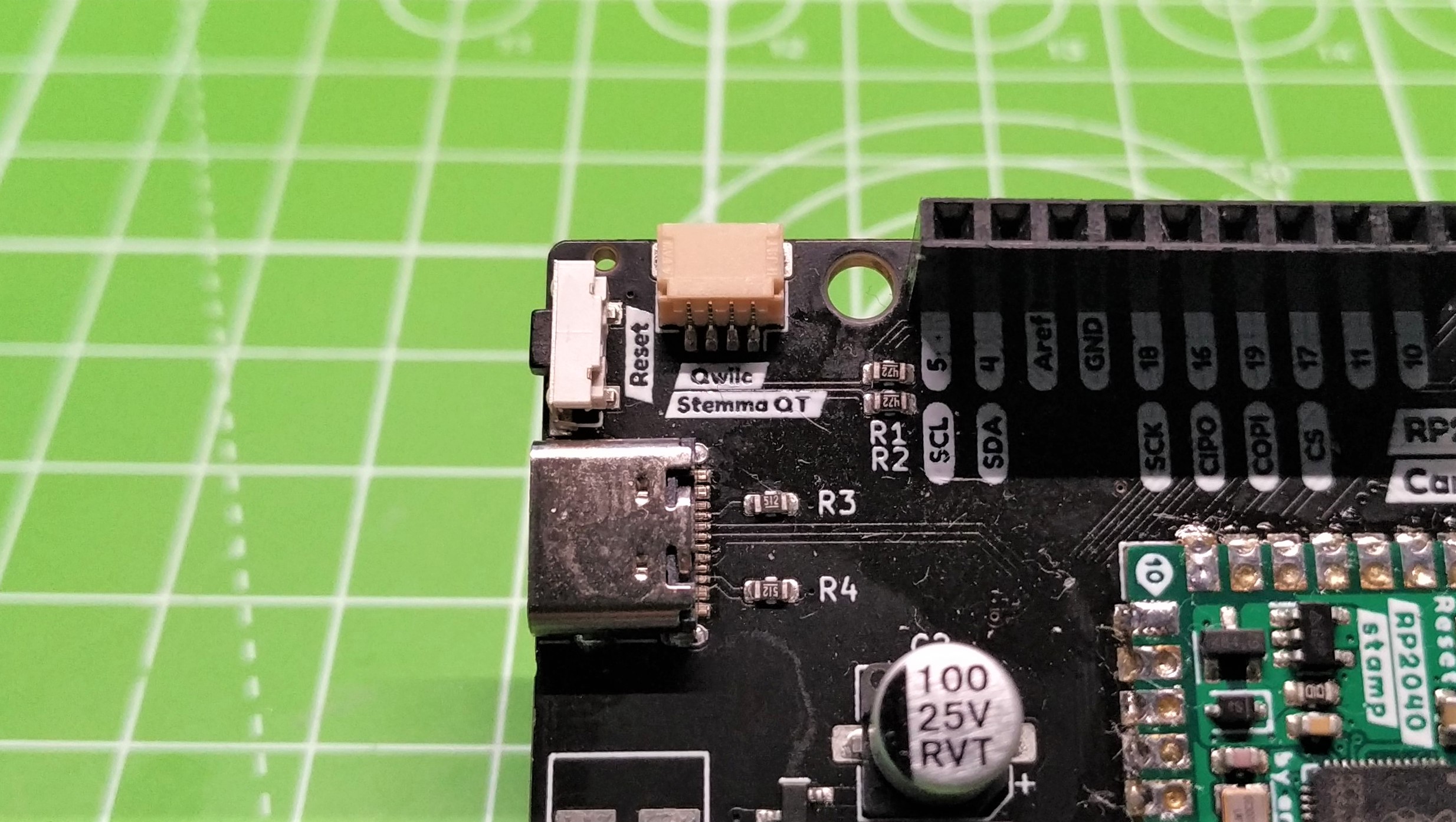
Now onto the more challenging stuff. The carrier board supports Stemma QT, Qwiic and QW/ST compatible boards, which makes interfacing with compatible devices a breeze. We dug around in our bits box and found the venerable MPR121 capacitive touch board. This is our go-to board for testing Stemma Qt / Qwiic / QW/ST connections as it is so simple to work with.
Touch one of the numbered inputs and it will print which was touched, and the current state. We put the code on the RP2040 Stamp, then saved to code.py. It was then that we saw an error in the Python shell; something was missing.
Normally we import the Board CircuitPython library to enable access to the GPIO pins. For RP2040 Stamp, we needed to modify the import so that we used import stamp_carrier_board as board. Stamp_carrier_board is a board specific version for the RP2040 Stamp. With that done we saved and ran the code and everything checked out with zero issues.
Use Cases for RP2040 Stamp
If you just need a breadboard compatible RP2040 board, then go and grab one of the best RP2040 boards. If you want to build your own RP2040 powered boards with custom PCBs, then Solder Party’s RP2040 Stamp is for you. Offering the footprints for the popular board design applications is a smart move. It means that board designers can just get on with making an RP2040 Stamp powered project.
Bottom Line
This isn’t for everyone, but if you need the power of the RP2040 in a small and convenient form factor, then RP2040 Stamp is for you. Ease of use, great form factor and a full GPIO make this a great way to make your own boards.
There is an alternative, in the form of Pimoroni’s PGA2040 which offers a similar, slightly smaller experience. PGA2040 has a 2.54mm pin pitch, which means it can be used with breakout headers, but due to the high pin density, it is not broadband compatible.
In our opinion we think that Solder Party’s offering is the better of the two, and that takes into consideration the 2mm pin pitch. We get a small board that breaks out all of the tricky wiring into a much easier-to-solder package.

Les Pounder is an associate editor at Tom's Hardware. He is a creative technologist and for seven years has created projects to educate and inspire minds both young and old. He has worked with the Raspberry Pi Foundation to write and deliver their teacher training program "Picademy".
