


In the 1980s and 90s the 9-pin D-Sub connector reigned supreme across the home computer scene. Atari, Commodore, Sega and many more used the ubiquitous connector for joysticks and pads. These controllers are our interface to the retro games that we love and that's why there’s nothing quite like implementing vintage hardware in your Raspberry Pi project. This project was originally from NickZero over at Instructables but we saw this via maker and developer Lee from More Fun Making It. The project relies on a Raspberry Pi Pico to convert a 9-pin D-Sub interface to USB in order to use an old-school joystick with his Raspberry Pi 400 Amiga project.
If you’re new to More Fun Making It, you’re in for a treat. Lee specializes in retro gaming and vintage tech—building arcade cabinets and pinball machines as well as repairing retro hardware, as the YouTube channel name suggests, just for the fun of it. This Pico-powered adapter is just one of many in his portfolio of projects and definitely one of the most useful when it comes to retrogaming.
Like many Pi projects, this one was born out of necessity. After setting up his Raspberry Pi 400 to run Pimiga—he realized that his Atari-ready Zipstick joystick had no way of connecting. To remedy this issue, he delved into this project that uses the RP2040 board to convert 9-pin D-Sub input to USB.


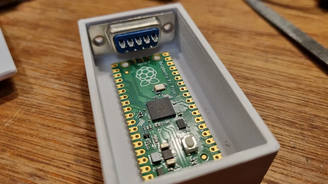
It doesn’t require much hardware to get off the ground with this adapter. It uses a Raspberry Pi Pico as the main board with a male 9-Pin D-Sub connector soldered to the GPIO. What is interesting about this project is that it doesn't use any logic level conversion. Typically the older 9-pin D-Sub connectors run at 5V, which isn't strictly compatible with the Pico's 3.3V GPIO. If we were to build this project we would use a logic level converter or a simple voltage divider (1K Ohm and 2K Ohm resistors will work; see resistor color codes to identify them) to ensure that the Pico's GPIO remains safe.
The housing is a simple, 3D-printed case held together with a couple of M2.5 screws and standoffs with access to both the D-Sub port and USB-C port. There is a top panel that can be removed to access the Pico hardware inside.
To aid in the construction process, Lee is using this Joystick to USB converter guide over at Instructables for help. The software used to program the adapter was created using Arduino IDE but it could be easily replicated in MicroPython or CircuitPython. We also have a guide on how to emulate Amiga on the Raspberry Pi if you’re interested in creating an Amiga-based Pi project of your own.
If you want to recreate this D-Sub to USB Raspberry Pi project, check out the original thread over at Twitter to get a closer look at how it goes together. Be sure to follow Lee for more cool retro projects as well as any updates on this one.
