APC's Current-Gen SurgeArrest: A Modern Tear-Down
After our first tear-down, APC wanted to send in a modern equivalent to demonstrate the company's dedication to quality. Follow along as we tear open another power strip and dig deep into its electrical composition.
Coax Protection
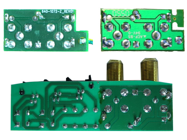
In the top-left corner, we have the new SurgeArrest. The top-right is APC's SurgeArrest from August's tear-down. And my oldest SurgeArrest is on the bottom.
The first two are identical except for the missing tab on the new bar's PCB. The elder's circuit board is also almost identical on the RF half. Apart from being mirrored horizontally, it has a link of some sort (a fuse, perhaps?) between its input F-connector and the remainder of RF traces instead of a very thin trace, like the other two. In other words, the hardware is practically unchanged from 10 to 15 years ago.
Phone Protection
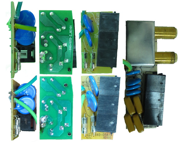
The top-left trio of images comes from the new model, while the bottom-left three are from August's tear-down. Their PCBs and components are identical apart from the silkscreen markings and solder mask colors.
My oldest unit has a considerably different phone surge suppression design using positive thermal coefficient (PTC) thermistors in a full four-wire configuration. The phone surge protection in the BX1000 UPS tear-down from last month had PTCs, but only on the primary phone pair. It looks like APC stopped using PTCs between the time I bought my oldest SurgeArrest/BX1000 and whenever I bought my other two SurgeArrest bars.
The Mains Course
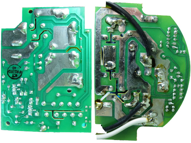
This is where things got interesting in my first SurgeArrest tear-down. All three power cable solder joints were bad in different ways, with half of the strands on the live wire not going through the PCB, the neutral wire not poking through the PCB and the ground wire with a blatantly obvious case of cold-solder. My third vintage bar, pictured on the right, does not have solder mask on its power traces like my other two, and it also has fewer routed-out gaps. Can you spot the soldering issue on the old unit's PCB, though? Here's a hint: it's near the mains neutral wire; solder blobs just right from dead-center.
The new model's PCB on the left is a little smaller with much shorter power traces, courtesy of the combination breaker switch. APC's soldering job looks about as good as it gets. The large copper areas without solder mask are tin-plated instead of sporting a solder coating. But considering how wide and short the power traces are, that extra step was likely unnecessary. I would expect no less from any power bar over $30...or any cost, for that matter, considering the potential safety implications.
Not Quite Flawless
Of course, when you look hard enough to find something worth criticizing, you usually find something. Just to prove that I really scrutinized, I found this: on the ground wire at the bottom, the solder blob has a void in the middle of the wire strands. It's not ideal, however, considering how narrow the trace is, that'll blow up long before soldering becomes an issue.
Get Tom's Hardware's best news and in-depth reviews, straight to your inbox.
Unlike the old models, where the outlet ground passed through the PCB, the new version's ground wire connects to the outlet ground strips first, so the PCB only needs the ground for wiring fault detection and occasional surges to ground, making it far less critical. Compared to what I found in my oldest unit on the next page or in August's tear-down, this is barely worth noting.
Forward To The Past
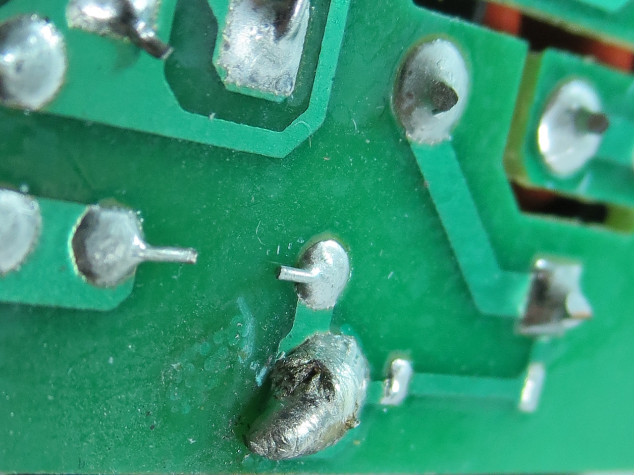
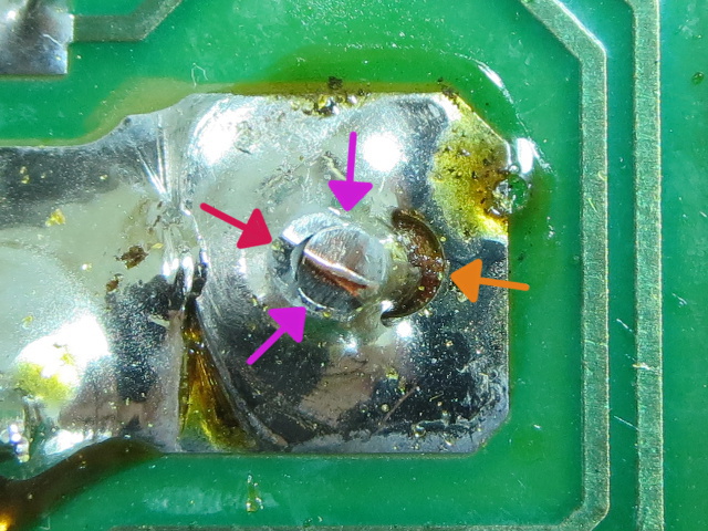
This picture was taken from my third 10+-year-old SurgeArrest, not the new unit. The new one's soldering is practically flawless.
Remember that bit earlier about opening my oldest SurgeArrest for curiosity's sake? It looks like I have one more bar with bad solder joints for the records. On the left, next to the red arrow, you can see that the solder and wire came apart when the wire got trimmed, indicating that the wire did not get hot enough for solder to bond properly. The rim around the wire with the purple arrows indicates that the solder bonding has also failed along the circumference. And the right side of the joint with the orange arrow simply has no solder on it. Since this is one leg of the neutral-side inductor, contact failure there would cause live mains voltage to show up on downstream “neutral” wires, becoming a shock hazard on non-grounded loads.
Better Than New
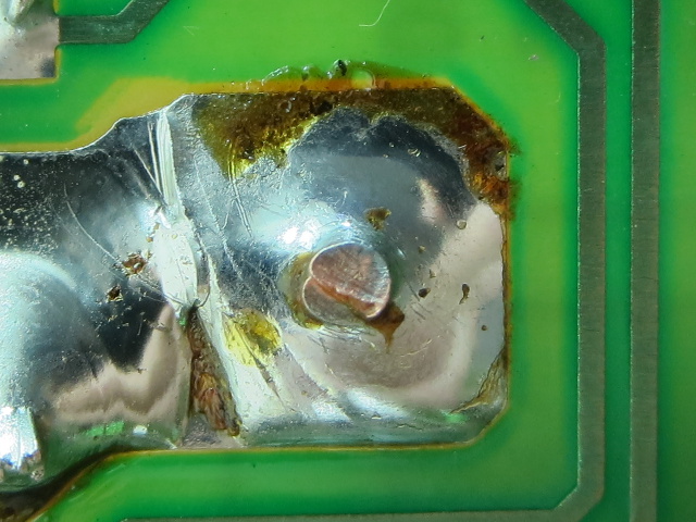
On the plus side, bad solder joints are usually very easy to fix. Apply heat, add solder if necessary and to help with heat transfer, reflow the whole pad and pin/wire until solder readily sticks to both. Remove the heat and you should end up with a nice, smooth and shiny solder joint.
With a thick copper wire and a large solder blob nearby, getting the joint to reflow takes a fair amount of heat. This is likely why the original joint ended up uneven and unbound. The yellow-brown stuff is just solder flux, nothing to worry about.
Two out of three units purchased about a year apart requiring rework is not a good average. Either I got extremely unlucky, or QA was not quite what it should have been back then.
Flipping The Boards
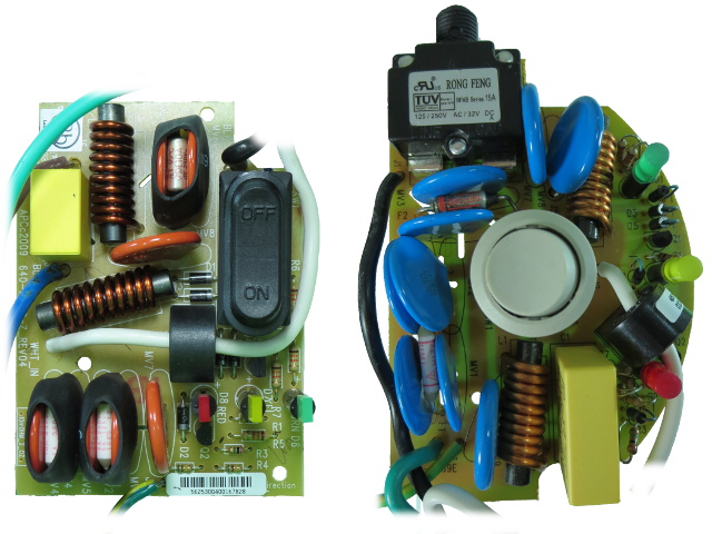
Removing the standalone breaker and accommodations for the switched outlets freed up a fair amount of space, enabling a less cluttered layout. It looks like APC did not start heat-shrinking MOVs to its thermal shutoff until some point after after my oldest bar was purchased. On the new one, each ground-side MOV pair gets bundled with a thermal protection instead of sharing one thermal fuse four ways. The two lone devices are GNR 20D471K and the others appear to be GNR 20D201K.
Without reverse-engineering the two boards, we can see that the type and count of individual components is mostly unchanged: the new model has one less MOV, one extra thermal shutoff, a much smaller 47nF X-cap and a combination breaker switch. Those appear to be the obvious parts list changes.
Two Sides Of The Same Coin
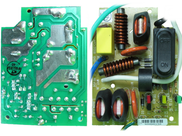
With both sides next to each other, we see the main thermal cut-off sandwiched between the top two MOVs in series with the live wire and switch, as expected. One of those MOVs goes from the fuse to the filtered neutral island in the middle (largest one), while the other goes from filtered live to unfiltered neutral. The horizontal un-fused MOV near the switch is directly across filtered live and neutral to catch what the other MOVs do not.
In the bottom-left corner of the component-side image, we have the four live-ground and line-ground MOVs with one MOV both before and after the inductors. The inner two MOVs are across ground and mains neutral, the middle one connects to filtered neutral, the fourth to unfiltered live and the outer MOV connects to filtered live. I really was not expecting this much snaking around with the MOV traces, nor such narrow traces, which are nothing like the older bar's fat solder-coated ones.
Testing, Testing
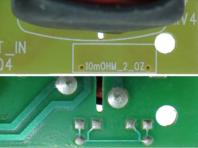
Considering how narrow the MOV traces are compared to the surge currents that may pass through them, the circuit board etching process and the copper thickness need to meet or exceed requirements with a high degree of confidence. APC tests for this using four-terminal “Kelvin” resistance measurement across a very narrow sample. If the copper is too thin or the etch too aggressive, this trace's resistance will exceed the control value. The only multimeter I own goes down to 0.1Ω, so I am two digits short of being able to tell it is there if I tried measuring it.
More Testing
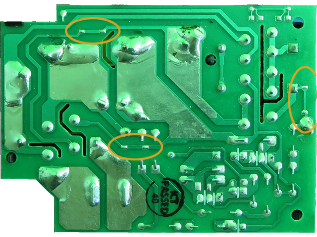
There are three pairs of middle-of-nowhere pads: two along the main MOVs' traces on the left and another along the ground path on the right. I solder-wicked two of those small blobs to see if they may have been solder fuses, but all I found underneath was the trace going through. I suspect those are additional test points, much like the trace in the previous slide. A Kelvin resistance measurement works by applying a known constant current through a circuit (a trace in this case) and measuring the voltage drop directly across the load (the piece of trace between test points) to calculate the load's resistance without having to worry about voltage drop in the source wires. This is why Kelvin resistance measurement requires four wires.
