Fractal Design Edison M Series 750W Power Supply Review
Why you can trust Tom's Hardware
A Look Inside And Component Analysis
Our main tools for disassembling PSUs are a Thermaltronics soldering and rework station and a Hakko 808 desoldering gun.
Parts Description
| Primary Side | |
|---|---|
| Transient Filter | 6x Y caps, 2x X caps, 3x CM chokes, 1x MOV |
| Inrush Protection | NTC Thermistor |
| Bridge Rectifier(s) | 1x GBU1506 |
| APFC MOSFETs | 2x Infineon SPP20N60C3 |
| APFC Boost Diode | 1x STTH8S06D |
| Hold-up Cap(s) | 1x Nippon Chemi-Con (420 V, 470 uF, 105 °C, KMQ) |
| Main Switchers | 2x Infineon IPP50R250CP |
| APFC Controller | Infineon ICE3PCS01 |
| Switching Controller | Infineon ICE2HS01G |
| Topology | Primary side: Half Bridge & LLC Resonant ConverterSecondary side: Synchronous Rectification & DC-DC converters |
| Secondary Side | |
| +12V MOSFETs | 2x NXP PSMN2R6-40YS, 2x SBR10U45 SBRs |
| 5V & 3.3V | 2x DC-DC Converters |
| Filtering Capacitors | Electrolytics: Nippon Chemi-Con, KY, KZH, 105 °CPolymers: Chemi-Con |
| Supervisor IC | SITI PS223 |
| Fan Model | HA1225M12F-Z (12V, 0.22A, Fluid Dynamic Bearing) |
| 5VSB Circuit | |
| Rectifying Diode | SBR10U45 |
| Standby PWM Controller | Infineon ICE2QR4765 |
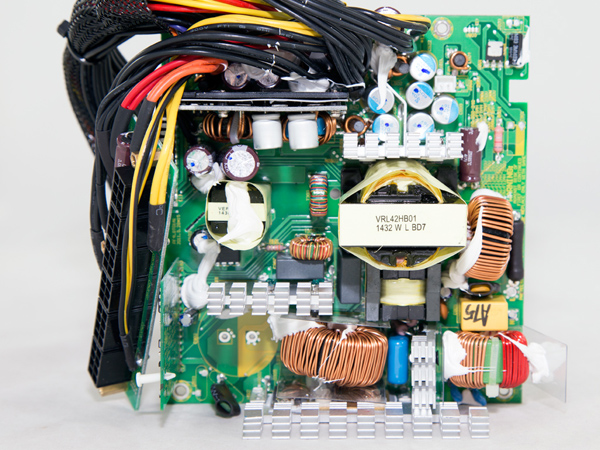
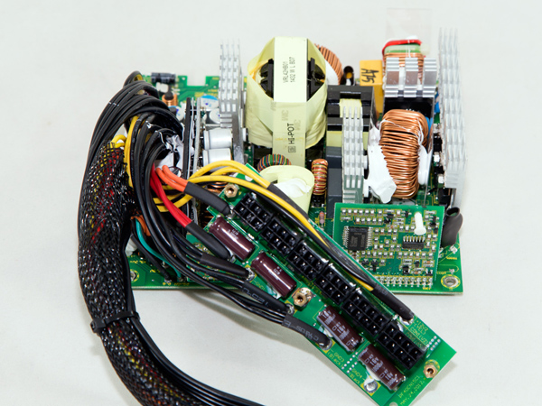
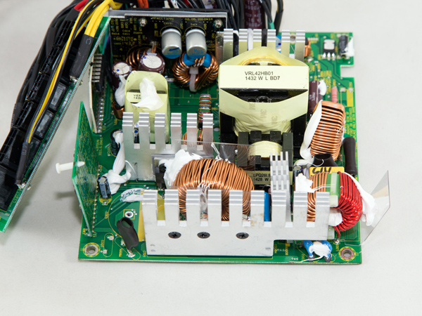
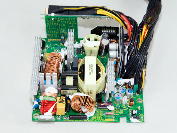
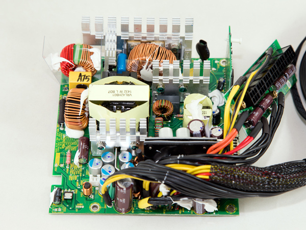
Fractal Design's Edison M units are based on the same platform as Seasonic's G-series PSUs. The platform uses a half-bridge topology in the primary side along with an LLC resonant converter, while in the secondary side a synchronous design is utilized for the rectification of the +12V rail along with two DC-DC converters for generating the minor rails. The quality of components is very high and all capacitors are provided by Chemi-Con, a highly reliable Japanese manufacturer.
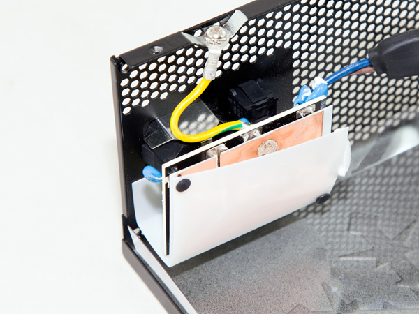
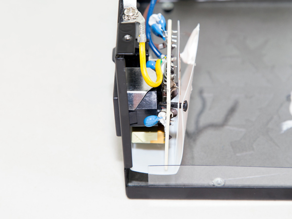
A small PCB behind the AC receptacle hosts the first part of the EMI filter, which includes four Y caps, a single X cap and a CM choke. The rest of the components of the EMI filter are located on the main PCB and consist of two CM chokes, two Y caps along with a single X cap and an MOV (metal oxide varistor).
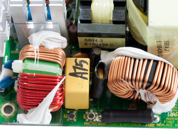
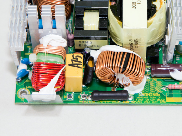
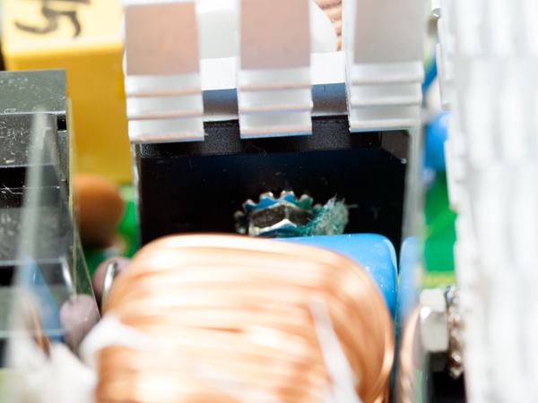
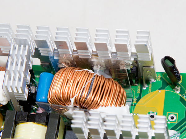
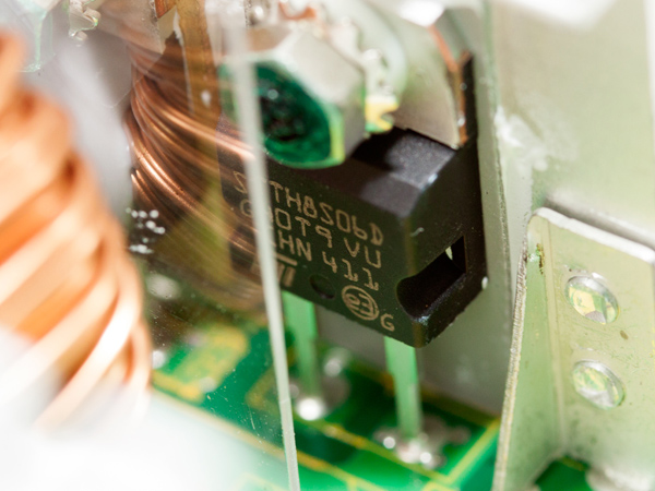
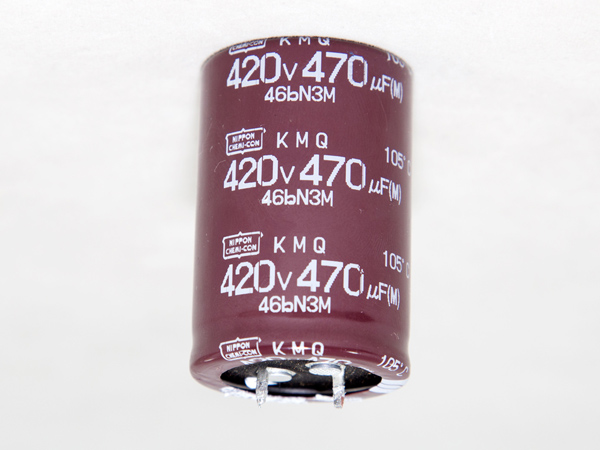
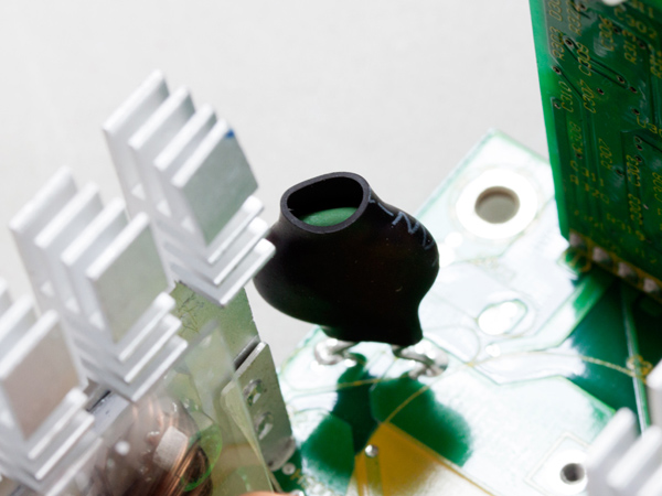
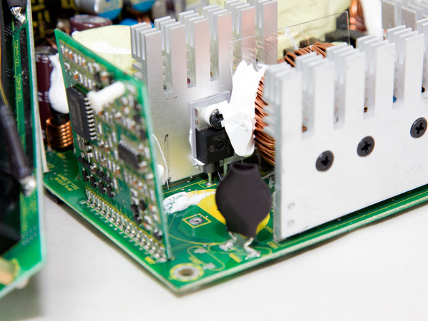
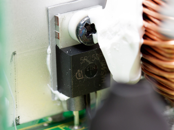
The single bridge rectifier (model number GBU1506) is bolted on a dedicated heat sink. After the bridge rectifier, the fully rectified voltage enters the APFC converter, which in this PSU uses two Infineon FETs (model number SPP20N60C3) and a boost diode (model STTH8S06D) to shape the current waveform and make it identical to the mains voltage in order to bring the power factor as close as possible to unity. Finally, close to the bulk cap is the NTC thermistor, which is responsible for protecting against large inrush currents. The only problem here is that, once the start-up phase finishes, there is no bypass relay for the thermistor, allowing it to cool down and regain its original resistance. We also didn't see a diode, which in some cases plays the same role as the relay mentioned above.
The main switchers are two Infineon (IPP50R250CP) FETs, arranged into a half-bridge topology.
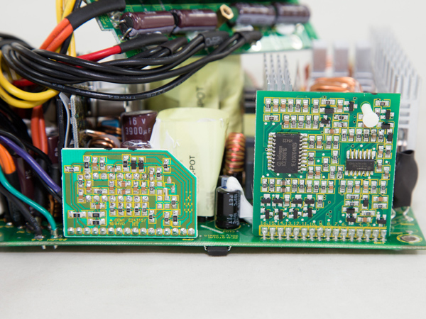
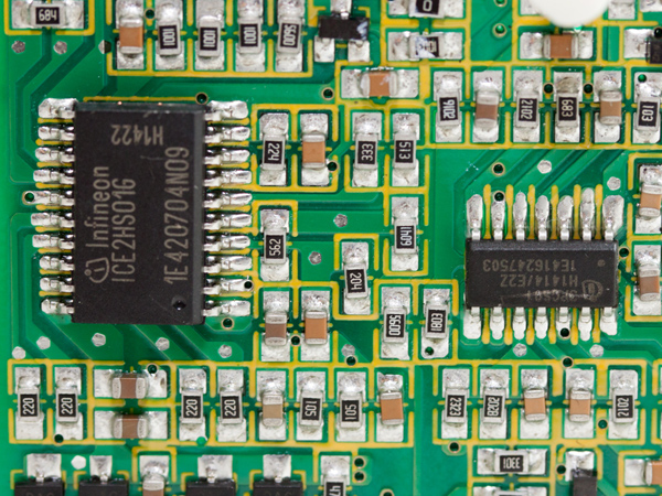
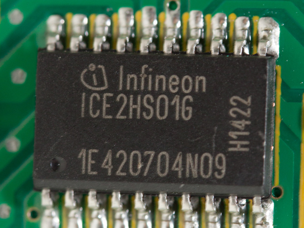
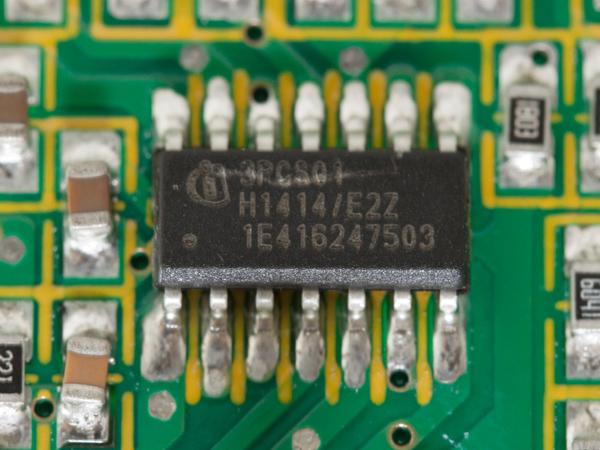
The resonant controller (the large IC on the left, model number ICE2HS01G) and the PFC controller (the small IC on the right, model number ICE3PCS01) are installed on a daughter board located in the primary side. The resonant controller operates in pulse-frequency modulation (PFM) mode, in which the repetition rate (or frequency) of fixed-duration pulses varies, unlike with PWM where the width of square pulses is varied at a constant frequency. In order to avoid high-frequency switching, the resonant controller employs missing cycle mode at light loads and burst mode with no load.
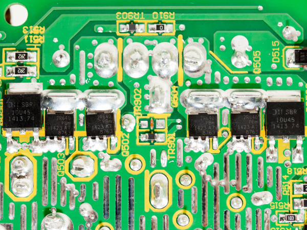
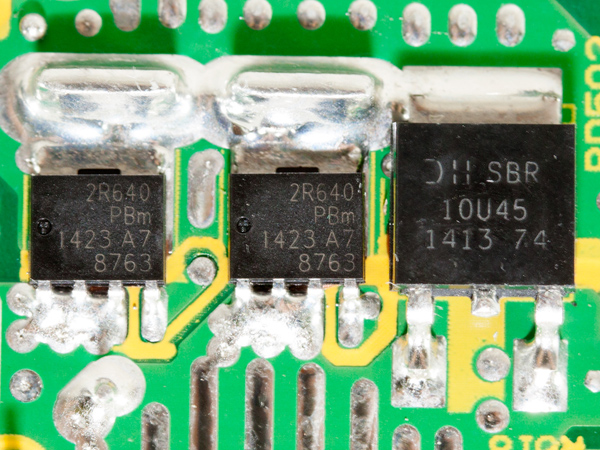
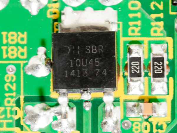
The four +12V FETs (model number PSMN2R6-40YS) are located on the solder side of the main PCB and are cooled by the heat sink above them and by the PSU's chassis as well. We also found two Schottky diodes (model number SBR10U45) on the sides of the FETs, which further increase efficiency by reducing switching loss, since they actually replace the body diodes of the slower FETs that have higher forward-voltage drops.
Get Tom's Hardware's best news and in-depth reviews, straight to your inbox.
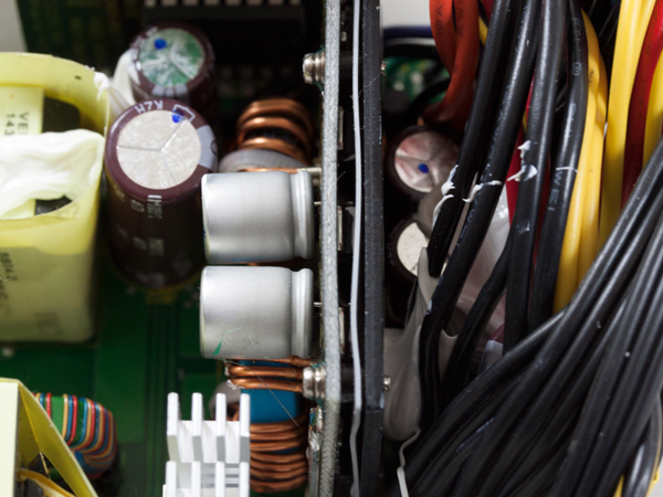
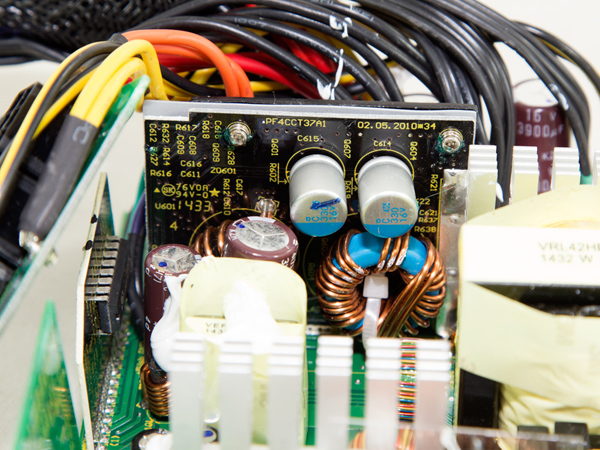
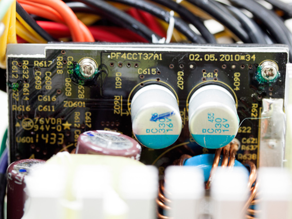
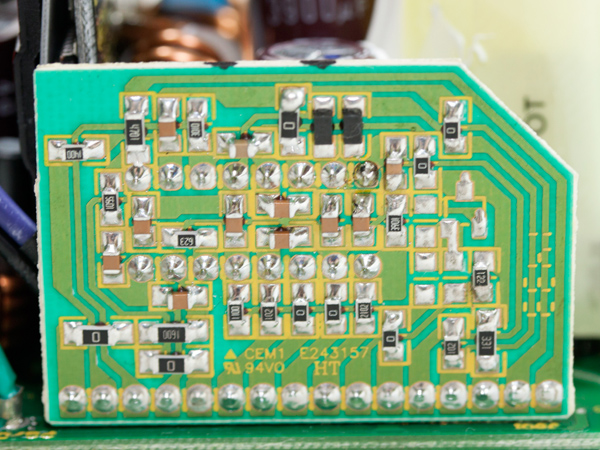
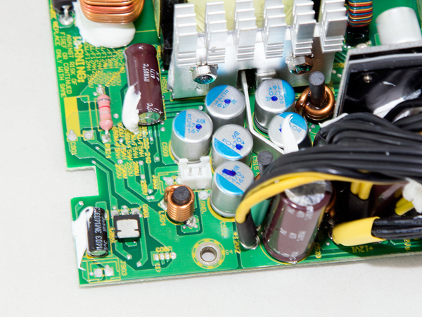
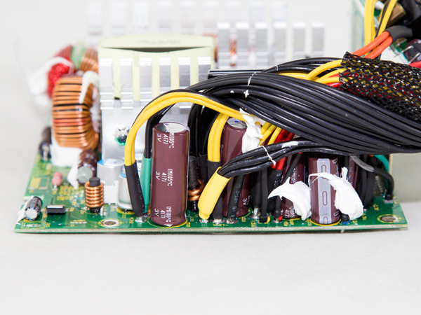
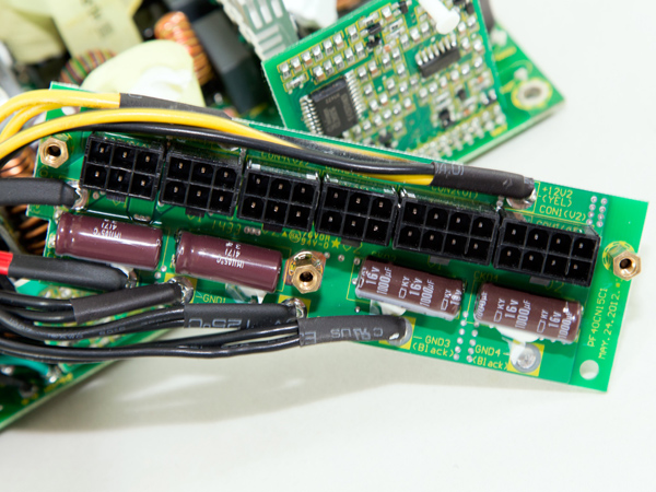
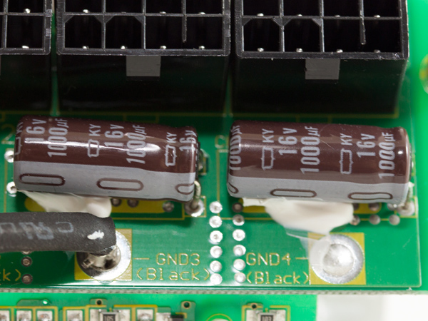
Both minor rails are generated by an equal number of DC-DC converters, which are hosted on the same vertical board. Unfortunately, there was no way to identify their PWM controller and FETs without completely disassembling the board.
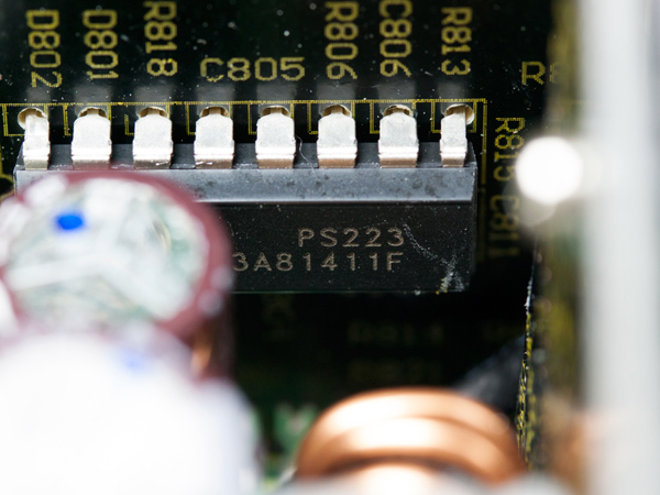
Housekeeping is handled by a SITI (PS223), which is among the few supervisor ICs that support OTP (over-temperature protection) out of the box.
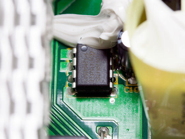
The standby PWM controller is an Infineon (model number ICE2QR4765); the Schottky diode responsible for 5VSB rectification (model number SBR10U45) is located on the solder side of the main PCB.
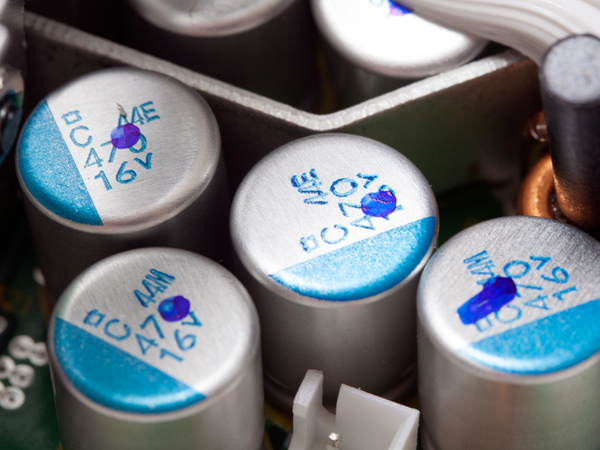
Several polymer caps along with some electrolytic caps filter the rails in the secondary side. All are provided by Chemi-Con, so they are of high quality. The electrolytic caps are rated at up to 105 degrees Celsius and they belong to the KY and KZH series. Given the high quality of the caps used in this unit, we see no reason that the PSU should not be able to deliver full power continuously at 50 degrees C. It seems that Seasonic was being cautious in this regard, or perhaps the company was afraid that the +12V FETs on the solder side of the main PCB would be exposed to excess heat in a worst-case scenario, which would affect their lifespan.
At the front side of the small PCB we also found several Chemi-Con electrolytic caps for some extra ripple filtering.
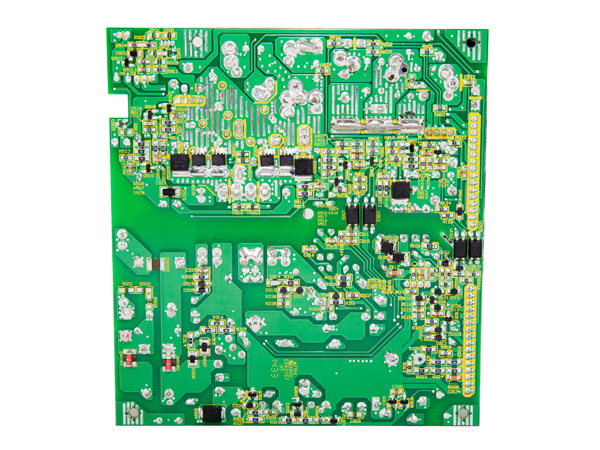
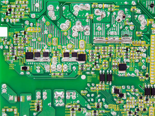
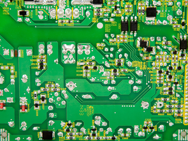
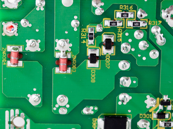
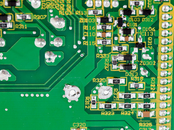
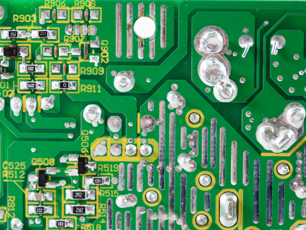
Soldering quality is definitely satisfactory. We didn't expect anything less from Seasonic.
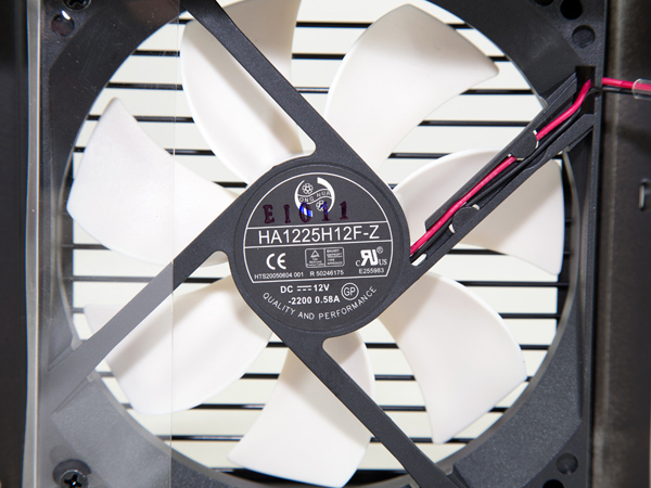
The cooling fan is provided by Hong Hua, Seasonic's preferred fan manufacturer for its affordable designs. The fan's model number is HA1225M12F-Z (12V, 0.22A, 2000 RPM, fluid dynamic bearing) and it will last for quite a long time thanks to the quality bearing that it uses. The only problem we see is the fan's small diameter, which forces it to spin at a high RPM in order to push a decent amount of air, leading to increased noise under stressful conditions.
Current page: A Look Inside And Component Analysis
Prev Page Packaging, Contents, Exterior And Cabling Next Page Load Regulation, Hold-Up Time And Inrush Current
Aris Mpitziopoulos is a contributing editor at Tom's Hardware, covering PSUs.
-
maxwellmelon there are several issues with there testing. first power good signal is not a good base for testing as its simple to "Cheat" the 16ms hold up.how about actually watching power good vs output voltages also. also the thermal camera scall changes every time how about using a fix scale as modifying scales leads to making things show hot that are not really that hot.Reply -
Aris_Mp First of all I measure AC loss to PWR_OK hold-up time since it is much easier to show it in my graphs and explain it. For me it is as easy to measure "AC loss to PWR_OK hold-up time" plus "PWR_OK inactive to DC loss delay" but I prefer it the way I do it.Reply
Also where do you base this? That the PG signal is simple to cheat and the manufacturers actually do this? From the moment the mainboards take seriously into account PG if this was the case then most likely there would be huge problems with lots of them. According to the ATX spec PG is de-asserted to a low state when any of the main rails falls out of 5% v. reg. Simply as that.
It just gives room for 1 ms till the PG signal sees the change at least in the ATX spec.
As for the thermal camera how it can show things hotter than it is? The scale is for this reason and from the moment the camera sees something from a different angle and a different region the scale is changing automatically. Nothing I can do about it. This is why I provide also actual temperature readings on all IR images.
-
PaulBags A quick opinion on the edison vs similar range seasonic own brand would be nice. Is it a new design, or an exact rebrand of a seasonic design? Quality of components vs?Reply -
Aris_Mp This is based on the same platform with the Seasonic G series and I state this in the "look inside" page. I haven't tested the G750 so far but I believe that since they are based on the same platform performance will be similar. Seasonic might used Enesol polymer caps (something that they usually do in their G units) instead of Chemi-Cons that Fractal chose, but both cap brands are very good so don't expect to see any real performance difference on them (although I prefer Chemi-Cons).Reply
So the design is nothing new and this is a Seasonic rebrand with minor differences at the internals (most likely the caps selection as I stated above). -
Aris_Mp Forgot to mention that besides caps the cooling fan is also different since on all Seasonic G units that I have tested so far have an ADDA double-ball bearing fan while the Edison PSU uses an FDB fan. However lately I noticed that many Seasonic units use Hong Hua FDB fans instead of ADDA double-ball bearing ones, so it is possible that this change might have affected the new bunches of G units.Reply -
Sakkura You say that you'd prefer if the unit was fully modular, but I don't really see the point.Reply
The fixed cables are the ones that will always be in use for any system using a 750W power supply, so the ability to disconnect those cables would not be beneficial. In fact it would lead to higher cost and also an extra point of failure and a slight loss of efficiency since a connector can never quite match an uninterrupted cable. -
Aris_Mp fully modular cables provide easier installation and cable management. Also you can easily change them with longer/shorter ones if you like or replace them in case there is a problem with them or simply you want something fancier.Reply
Loss of efficiency isn't a reason any more, on the contrary with bus bars or thick cables transferring power to the modular PCB energy losses can be minimized. In addition no cables block the secondary side caps, something that besides increasing their lifetime also allows for more relaxed fan profiles and better airflow inside the chassis.
Also the cost of a semi-modular to fully modular isn't high and in a 750 W PSU that costs 140 bucks already the cost reason doesn't stand (for fully modular design). -
Sakkura Reply
No they don't. The connector on the power supply end adds complexity and reduces cable flexibility.15924995 said:fully modular cables provide easier installation and cable management. Also you can easily change them with longer/shorter ones if you like or replace them in case there is a problem with them or simply you want something fancier.
You cannot easily change them because other cables are often incompatible - there is no common standard for modular PSU cables. Using incompatible cables can be downright dangerous. Here is a cautionary tale. -
Aris_Mp I didn't say that you can change them with anything, did I? Also it is common sense that every manufacturer uses their one design on modular cables. Thing is that with modular PSUs you can get an extra cable kit since most manufacturers sell one for their PSUs (e.g. Corsair, EVGA).Reply
Also I still cannot understand how the connector on the PSU end adds complexity and reduces cable flexibility! Cable flexibility depends on the gauges' thickness and not on the cables modularity design (or not).
Anyway I believe I made my opinion clear on why I prefer fully-modular PSUs.
