LCD Or Plasma - What's Your Pleasure? Understanding Modern Flat-Panel TV Technologies
From Fluorescent Tube To Plasma Pixel
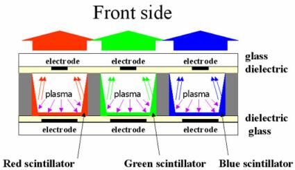
The application of this technology to pixels in a plasma display is fairly straight-forward. Each pixel is made up of three identical microscopic cavities containing a rare gas (xenon) and having two electrodes, front and rear. By applying strong alternating current to each electrode, the plasma contained in the cavities is set in motion. The plasma emits UV rays (shown in violet on the diagram) that hit the scintillators at the bottom of each cavity. These scintillators are chosen to emit one primary color each - red, green, or blue. The colored light then passes through the glass and the user sees it.
While plasma pixels operate fairly similarly to fluorescent tubes, fabricating complete panels of them does pose a few technical problems. The first difficulty manufacturers run into is inherent in the size of the pixels themselves. A plasma sub-pixel represents a volume of 200µm x 200µm x 100µm, and it's no mean feat to assemble several million of them side by side. Then, the front electrode must be made as transparent as possible; ITO (indium tin oxide) is used because it's both conductive and transparent. Unfortunately, plasma displays can be so large, and the ITO layer so thin, that the electrical resistance of the material becomes too great to ensure good propagation of the voltage (some 300 volts). So a fine line of chromium is often added as well, which is a much better conductor but is unfortunately opaque.
Finally, the right scintillators (also called luminophores) have to be found. The ones used in plasma pixels depend on the desired color:
- Green : Zn2SiO4:Mn2+ / BaAl12O19:Mn2+
- Red : Y2O3:Eu3+ / Y0,65Gd0,35BO3:Eu3
- Blue : BaMgAl10O17:Eu2+
These three luminophores produce wavelengths of between 510 and 525 nm for green, 610 nm for red, and 450 nm for blue. (Yes, the exact chemical formulas aren't important for understanding how plasma screens work, but our chemist friends will appreciate them!)
The last problem is that of how to address the pixels, because as we've seen, to get different color shades the light intensity of the three primary-color sub-pixels has to be varied independently.
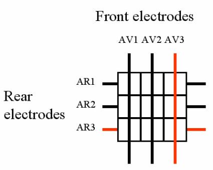
On a 1280x768-pixel plasma panel, there are approximately three million sub-pixels, with six million electrodes. Obviously, it's impossible to route six million lines to control the sub-pixels independently, so the lines are multiplexed. The front lines are common to an entire row, and the rear ones are common to an entire column. The onboard electronics in plasma displays successively chooses the pixels that need to be lighted on the panel. This operation is done very quickly, and so is invisible to the user - a little like the scanning on CRT monitors.
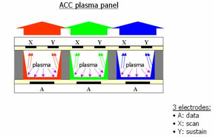
There are other types of plasma panels, but we won't go into detail about them here. The most common variant currently is the alternative coplanar current (ACC) panel. It has three electrodes per pixel instead of two.
Get Tom's Hardware's best news and in-depth reviews, straight to your inbox.
For transparency, the front (scan and sustain) electrodes are made of ITO.
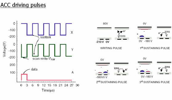
Control is more complex for ACC panels, but their main advantage is the ability to maintain the flow of the plasma longer than on a traditional panel. In the first stage, a strong difference in potential of 300 V, applied as +100V and -200V between the scan and data electrodes, creates a "wall" of charge. Then, the charges are alternated between scan and sustain by applying alternating current between the two electrodes (+180V, -180V, +180V, etc.) The advantage is that the flow can be maintained while keeping the data electrode free to address another pixel. In the same way, the discharges can be interrupted by using this data electrode.
Current page: From Fluorescent Tube To Plasma Pixel
Prev Page A "Simple" Basic Principle Next Page Advantages And Disadvantages Of Plasma Displays


