Pi in the Sky: Build a Retro Flight Sim Controller With Raspberry Pi
Play retro versions of Microsoft’s Flight Simulator on a Raspberry Pi using a custom flight controller.
There is no escaping Microsoft’s latest Flight Simulator. Beautiful visuals, a fully configurable world where we can control the weather and time of day. To run the latest version you need a beast of a PC (see our article Flight simulator performance benchmarks) , but if you are willing to compromise then you can simulate Microsoft Flight Simulator 4, from 1989, using your web browser. The Raspberry Pi 3 or 4 has enough power to run the simulation and it has a GPIO which, with a little Python code, we can use to interface real controls for our simulator experience.
What You Need to Make a Flight Controller
- Raspberry Pi 3 or better
- A micro switched arcade style joystick
- 10 x Push buttons
- 4 x Screw terminals (4 pole)
- 45 Female to male jumper wires
- 4ft of wire
- Breadboard
- A case to mount the controls. This would be ideal
- A power drill with a small drill bit and a stepped drill bit
- Soldering equipment including heat shrink tubing and wire stripper
- Multimeter
Wiring and Hardware of Raspberry Pi Flight Controller
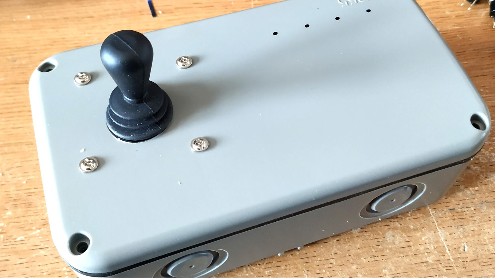
1. On the case, mark where the controls will be placed. Do this to ensure that there is space for all of the components and that it is comfortable to use.
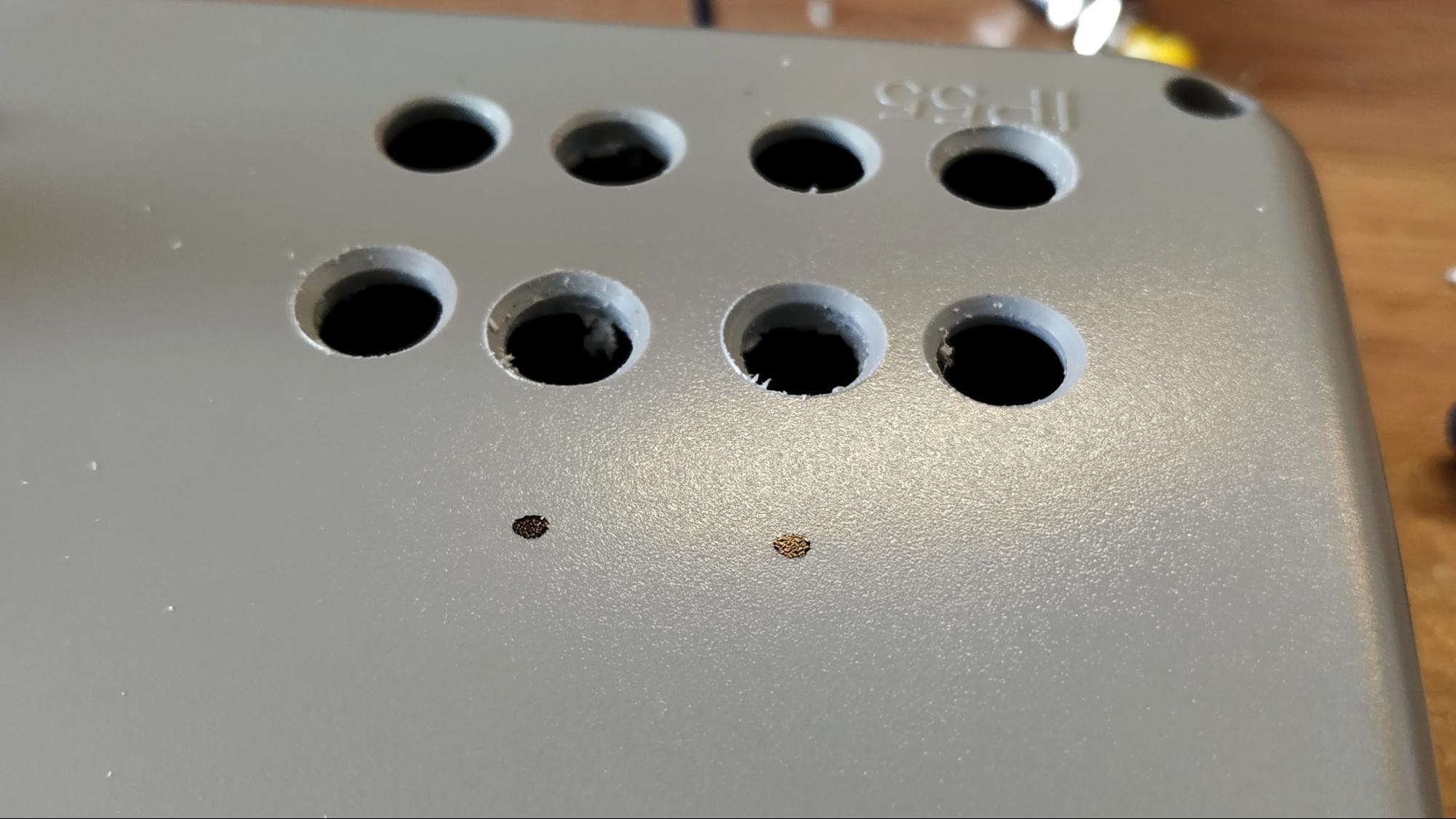
2. Using the small drill bit, drill a pilot hole for the component. Swap to the stepped drill bit and drill to match the size of the component. Stop frequently and check sizes. Also drill a ½ inch hole to route the wires out to the Pi.
3. Test fit all of the components.
4. Remove the joystick from the case and ensure that it is firmly held in place before soldering. Prepare your workspace and then warm up the soldering iron.
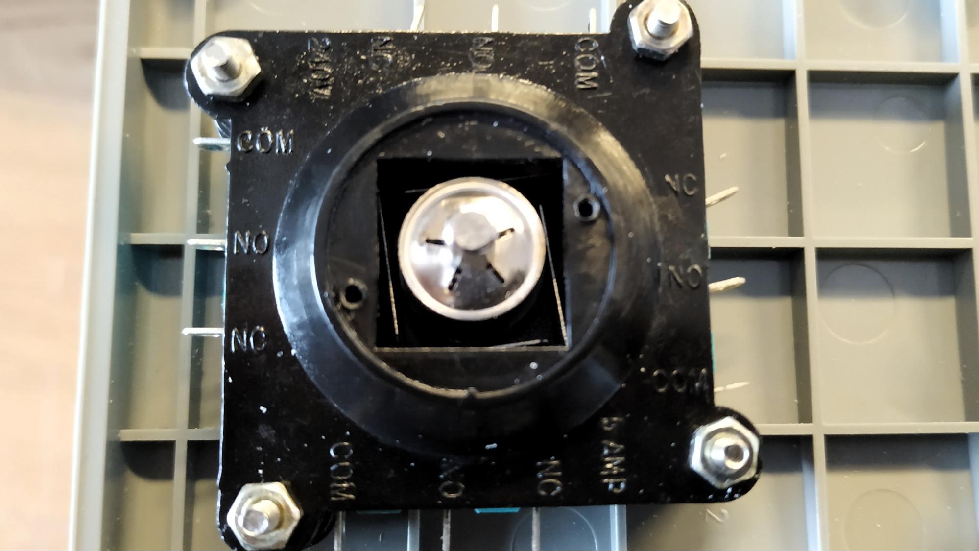
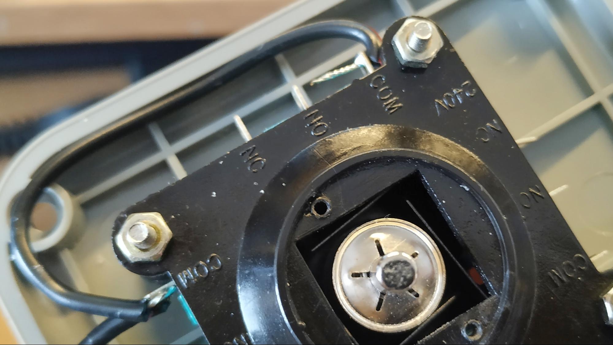
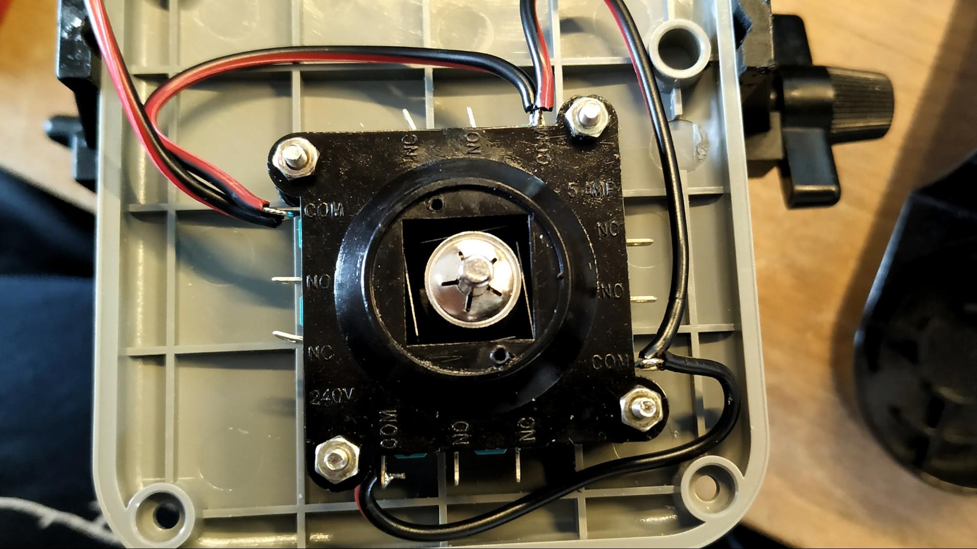
5. If your joystick has four switches around the perimeter of the case, look for COM on each switch. Apply a small amount of solder to the COM connectors. If your joystick has a single connector with five pins, apply a small amount of solder to the COM / GND pin.
6. Take the length of wire, strip ¼ inch from the end and twist the bare wires into a spiral. Apply a small amount of solder to the wires. Solder the wire to a COM / GND pin on the joystick. If you are using a single connector with five pin joystick, please skip to step 9.
Get Tom's Hardware's best news and in-depth reviews, straight to your inbox.
7. Move to the next COM pin and measure the wire to the COM pin. Add another ½ inch to the measurement and then use the wire stripper to expose the wires. Do not cut the wire!
8. With the wire exposed, flow a little solder on to the bare wire and then carefully solder the wire to the COM pin. Repeat this process for the remaining COM pins.
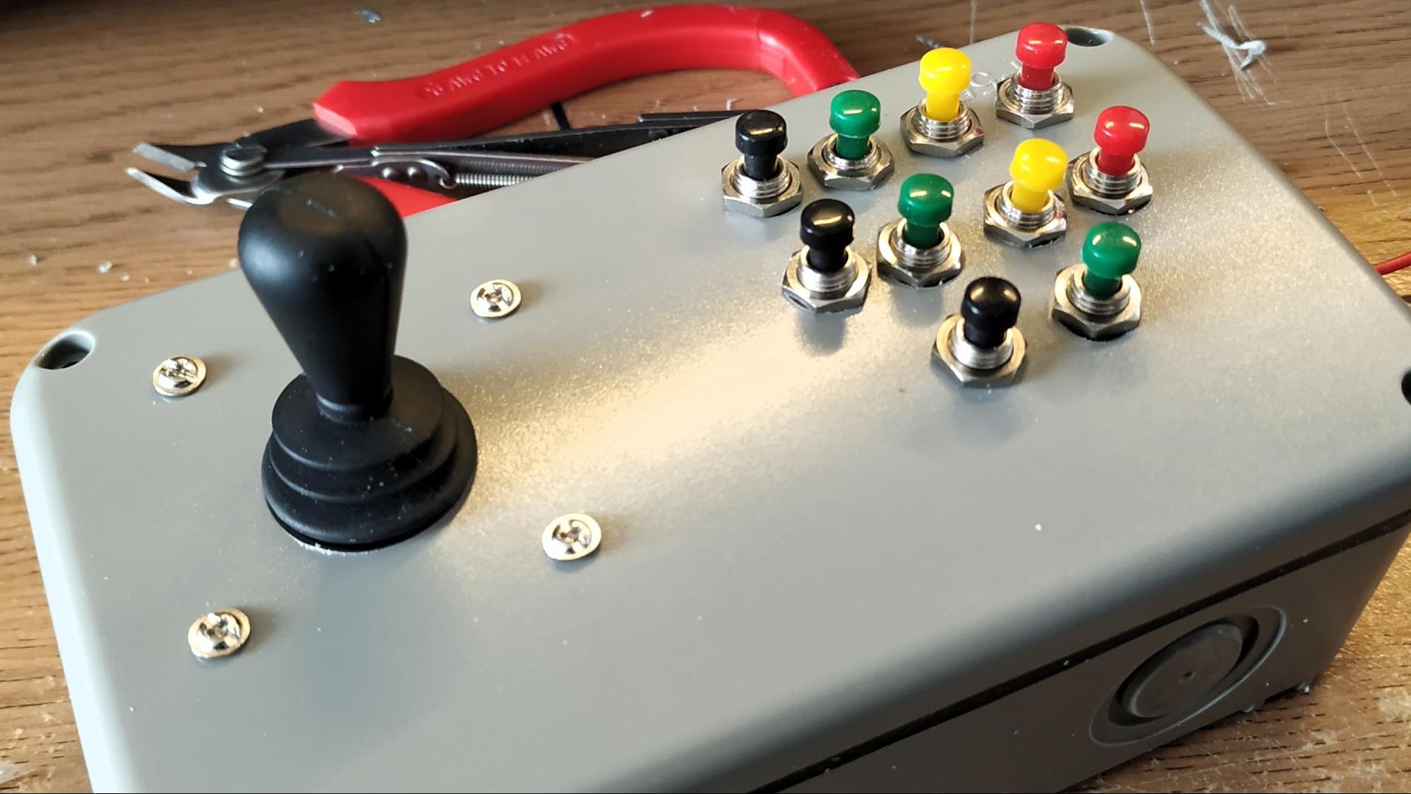
9. Fit the joystick into the case and secure in place using screws. Also fit the pushbuttons to the case and secure in place.
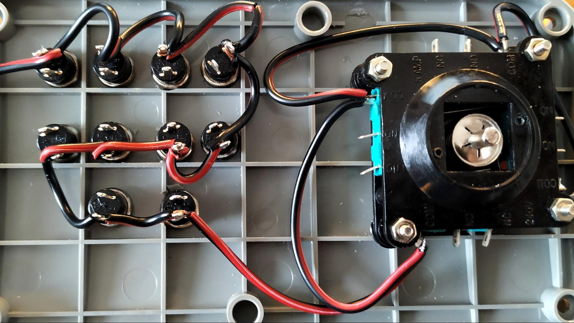
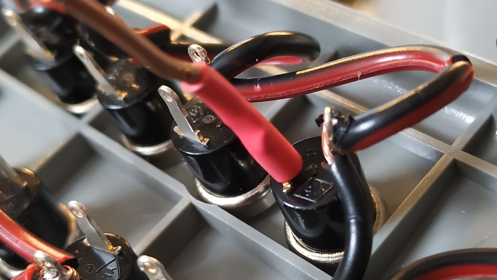
10. Run the wire from the joystick COM / GND pins to one leg of the first button. Add another ½ inch to the length of wire and strip the sleeving from the wire. But do not cut the wire. Flow a little solder on the bare wire and one leg of the button. Attach the wire to the leg of the button using a little more solder. Repeat this for one leg on every button.
11. Trim the wire so that there is around 6 inches of slack. Strip the end of the wire, twist the bare wires and flow a little solder to the wires.
12. Snip the female end off of four jumper wires. Strip the sleeving and twist the bare wires into a spiral. For each wire flow solder onto the bare copper wires. An optional step is to use heat shrink tubing to secure the wire to the pin, and prevent accidental electrical shorts.
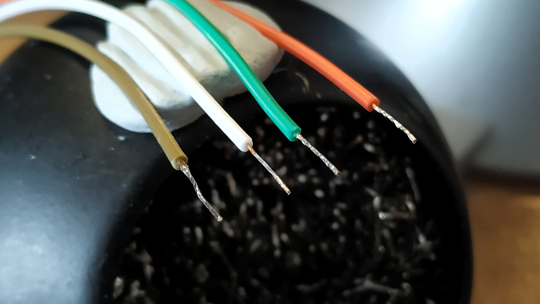
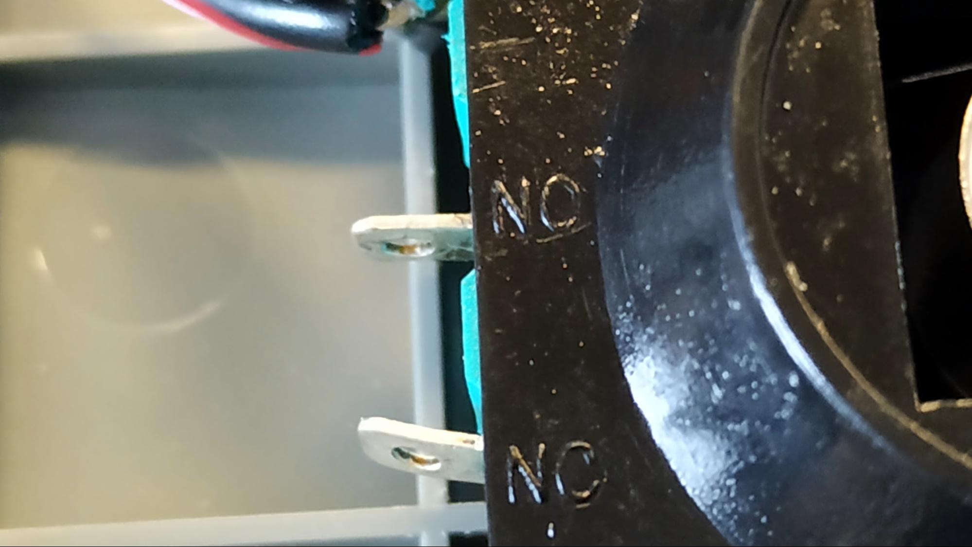
13. Flow solder on to the NO (Normally open) connections for each switch on the joystick. If using a single connector five pin joystick, flow a little solder onto the four connectors. Connect the jumper wires to the connections.
14. Cut the female ends of ten jumper wires, strip the sleeving, twist the wires and flow a little solder to each of the bare wires. Heatshrink can be used to prevent electrical shorts.
15. Using a little solder, connect the jumper wires to each of the spare push button legs, then slide the heat shrink tubing over the leg and heat the tubing to shrink in place.
There should now be 15 connections. From all of the buttons, and directions of the joystick, and a single GND connection that connects to every COM pin on the joystick and one leg of each button.
16. Set your multimeter to continuity mode and place one probe at one end of the COM / GND connection, and the other at the bare wire at the tip. You should hear a beep confirming that everything is connected.
17. Insert the four screw terminals into the breadboard and then take the jumper wires from the joystick, noting which is up, down, left and right. Place the wires into the breadboard so that they are inline with the screw.
18. Repeat this for every jumper wire for every button, and finally the GND connection which has its own screw terminal. There should be 15 screw terminals in use, and a single spare terminal.
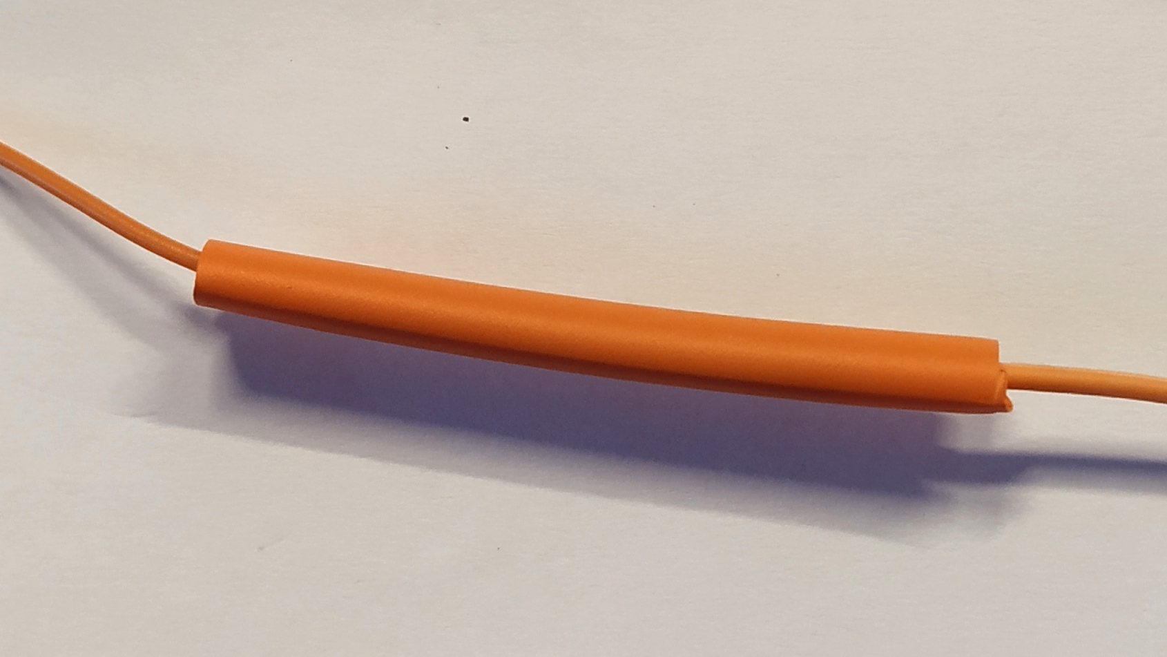
19. Take two female to male jumper wires. Connect them together to form a longer jumper wire. Slide a length of heat shrink around the connection and heat the connection to secure it. Tape can be used in lieu of heat shrink. Repeat this process so that there are 15 extended wires.
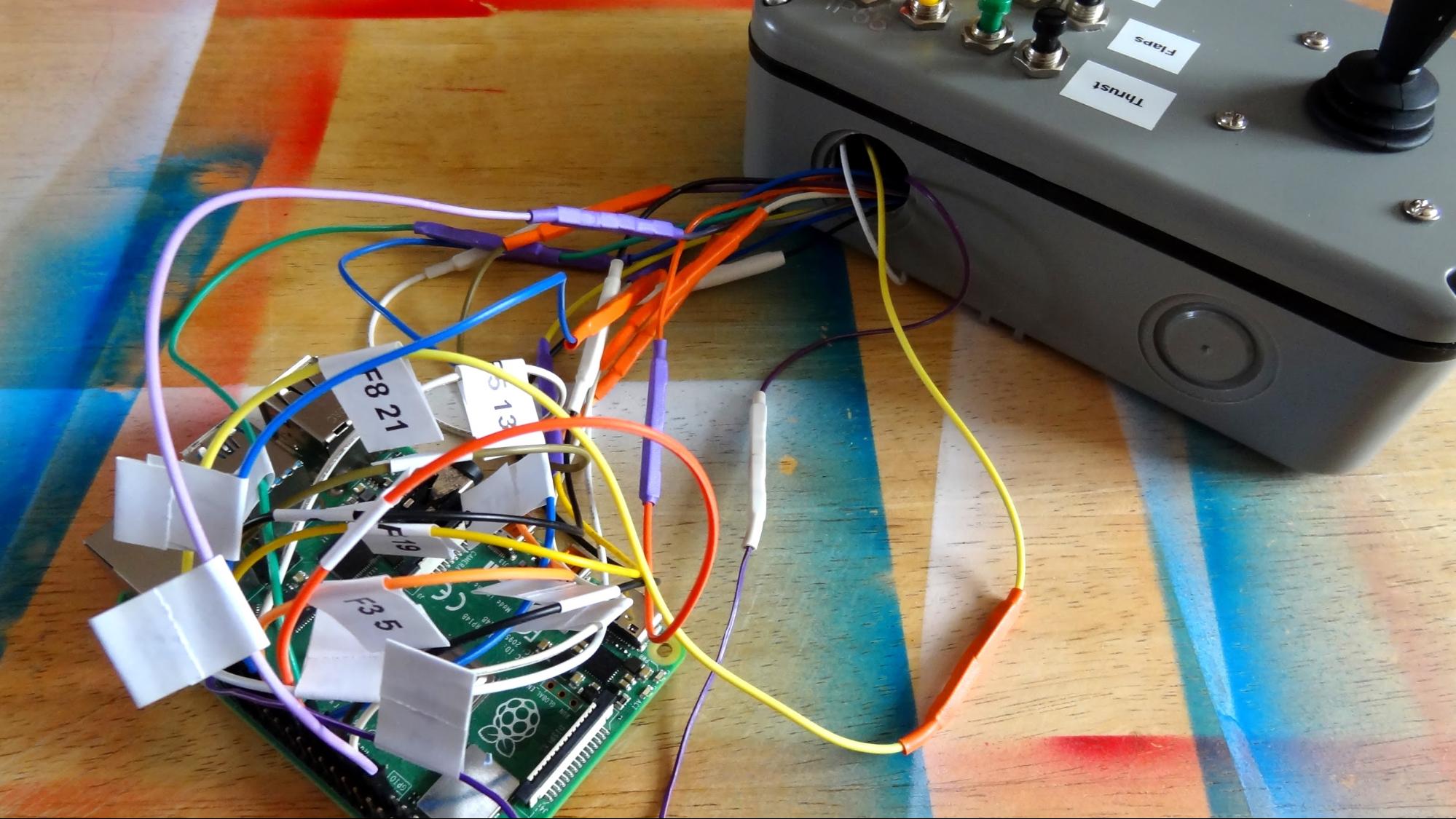
20. Screw the male end of the wire into the screw terminal and feed it through the hole in the case. Make a note of what each wire connects to. We used a label printer, but tape and a pen will work just as well.
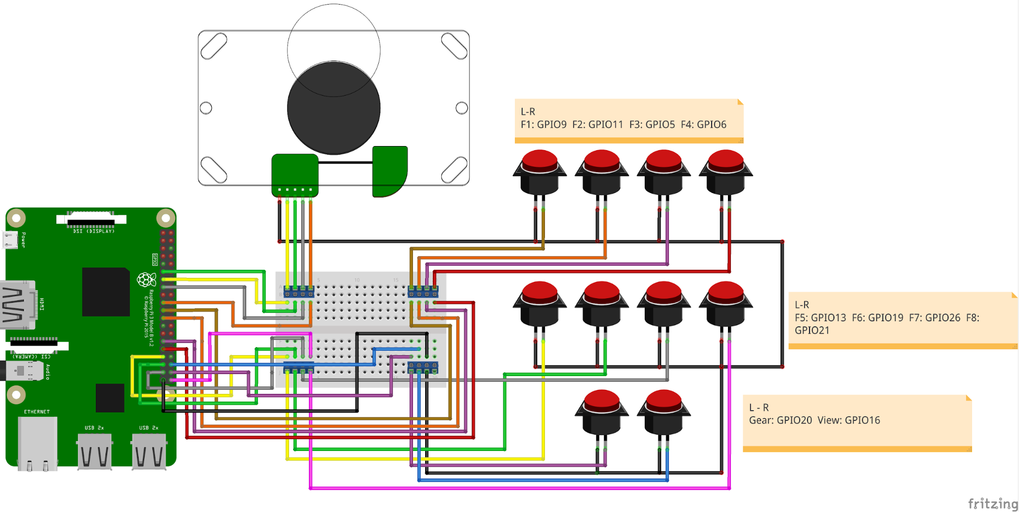
21. Connect the buttons to the GPIO on the Raspberry Pi as per the diagram.
22. Connect your Pi accessories and boot the Raspberry Pi to the desktop.
Software Setup of Raspberry Pi Flight Controller
23. Open a Terminal and install pynput, a Python module for simulating keyboard input.
sudo pip3 install pynput24. Open Thonny from the Programming menu.
25. Import three modules, pynput for keyboard simulation, gpiozero to work with the GPIO pins and time to control the pace of our project.
from pynput.keyboard import Key, Controller
from gpiozero import Button
from time import sleep
26. Create a connection between the pynput code and a virtual keyboard.
keyboard = Controller()27. Each of the buttons and joystick are physically connected to the GPIO of the Raspberry Pi, and now we need to tell Python where to find each button and for each button to have a reference that tells us what the button is for.
Up = Button (27)
Down = Button(17)
Left = Button(10)
Right = Button(22)
F1 = Button(9)
F2 = Button(11)
F3 = Button(5)
F4 = Button(6)
F5 = Button(13)
F6 = Button(19)
F7 = Button(26)
F8 = Button(21)
Gear = Button(20)
View = Button(16)
28. Create an infinite loop which will constantly run the code.
while True:Inside the loop we start a series of conditional statements, tests that will check the status of each button / joystick direction everytime the loop goes round. If a button is pressed then the code for that test is run. The first test is to see if the joystick has been pressed up. If that is true then the code will simulate pressing the up arrow key every 0.1 seconds.
        if Up.is_pressed:
    	print("Up")
    	keyboard.press(Key.up)
    	sleep(0.1)
    	keyboard.release(Key.up)
30. The next test will check to see if the down direction has been pressed.
        elif Down.is_pressed:
    	print("Down")
    	keyboard.press(Key.down)
    	sleep(0.1)
    	keyboard.release(Key.down)
31. Enter the code for left and right.
        elif Left.is_pressed:
    	print("Left")
    	keyboard.press(Key.left)
    	sleep(0.1)
    	keyboard.release(Key.left)
	elif Right.is_pressed:
    	print("Right")
    	keyboard.press(Key.right)
    	sleep(0.1)
    	keyboard.release(Key.right)
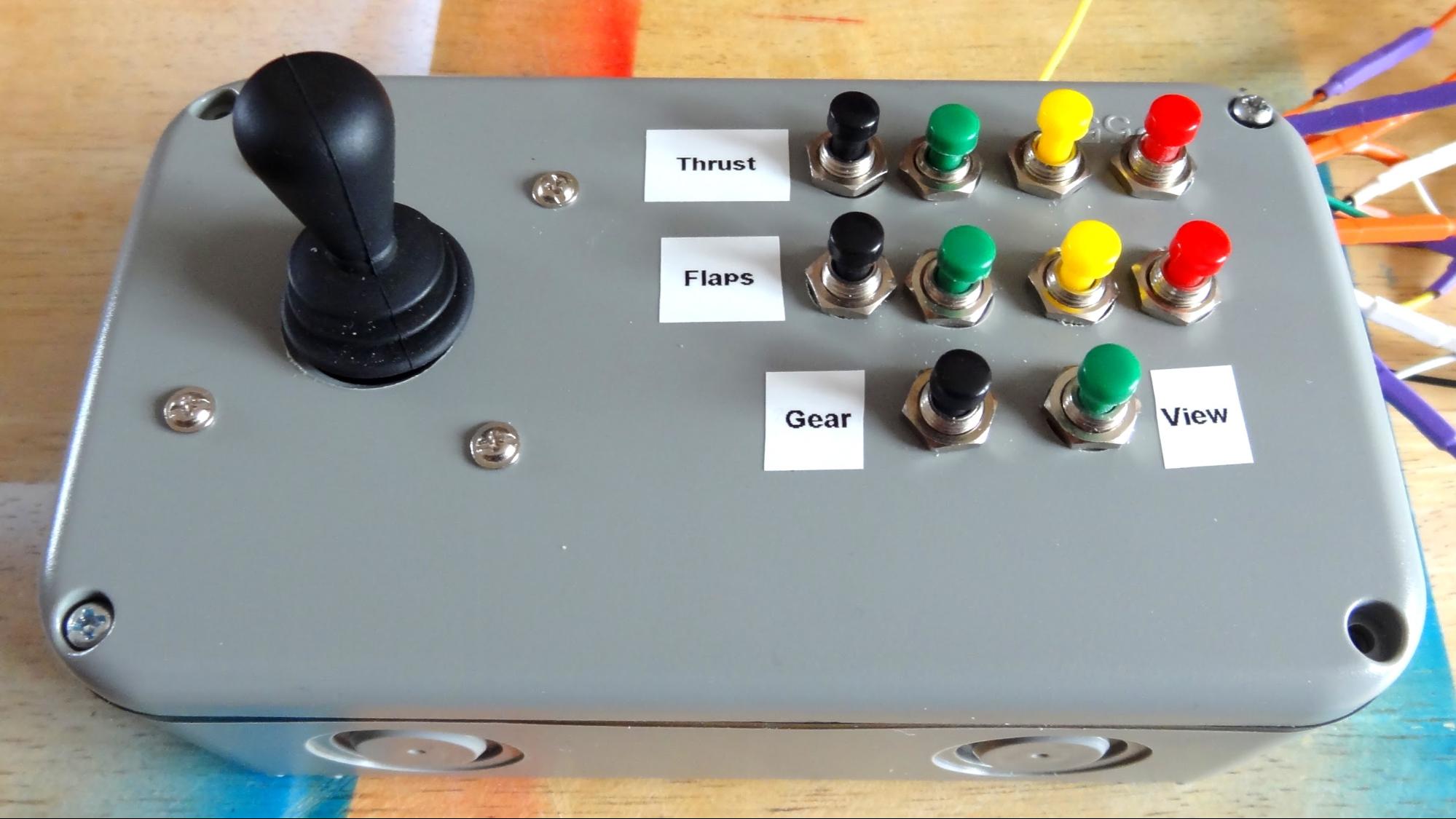
32. Map the thrust keys to F1 to F4. With F1 turning the engines on to 25% power, and F4 being full power. These are mapped to the top row of buttons on the controller.
        elif F1.is_pressed:
    	print("Engine Power 25%")
    	keyboard.press(Key.f1)
    	sleep(0.1)
    	keyboard.release(Key.f1)
	elif F2.is_pressed:
    	print("Engine Power 50%")
    	keyboard.press(Key.f2)
    	sleep(0.1)
    	keyboard.release(Key.f2)
	elif F3.is_pressed:
    	print("Engine Power 75%")
    	keyboard.press(Key.f3)
    	sleep(0.1)
    	keyboard.release(Key.f3)
	elif F4.is_pressed:
    	print("Engine Power 100%")
    	keyboard.press(Key.f4)
    	sleep(0.1)
    	keyboard.release(Key.f4)
33. Map Flap control, used to create drag, to F5 to F8 and this is the second row on the controller.
        elif F5.is_pressed:
    	print("Flaps Position 1")
    	keyboard.press(Key.f5)
    	sleep(0.1)
    	keyboard.release(Key.f5)
	elif F6.is_pressed:
    	print("Flaps Position 2")
    	keyboard.press(Key.f6)
    	sleep(0.1)
    	keyboard.release(Key.f6)
	elif F7.is_pressed:
    	print("Flaps Position 3")
    	keyboard.press(Key.f7)
    	sleep(0.1)
    	keyboard.release(Key.f7)
	elif F8.is_pressed:
    	print("Flaps Position 4")
    	keyboard.press(Key.f8)
    	sleep(0.1)
    	keyboard.release(Key.f8)
34. Map the last two buttons to the landing gear, and to change the views.
        elif Gear.is_pressed:
    	print("Gear Toggle")
    	keyboard.press("g")
    	sleep(0.1)
    	keyboard.release("g")
	elif View.is_pressed:
    	print("View Toggle")
    	keyboard.press("s")
    	sleep(0.1)
keyboard.release("s")
35. Save the code as flight.py and click on the start button to run.
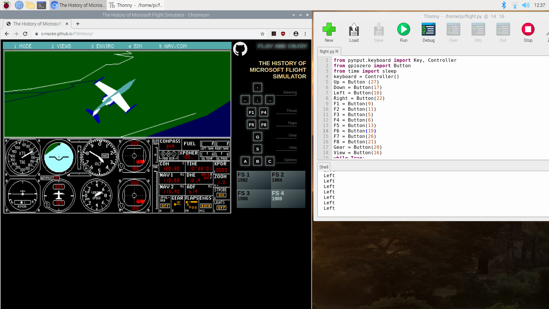
36. Open the web browser to https://s-macke.github.io/FSHistory/ and ensure that the browser window is selected. Now grab your controller, press 100% thrust and watch as the world around you changes into a 1980s flight simulator with you at the controls!
Complete Code Listing
from pynput.keyboard import Key, Controller
from gpiozero import Button
from time import sleep
keyboard = Controller()
Up = Button (27)
Down = Button(17)
Left = Button(10)
Right = Button(22)
F1 = Button(9)
F2 = Button(11)
F3 = Button(5)
F4 = Button(6)
F5 = Button(13)
F6 = Button(19)
F7 = Button(26)
F8 = Button(21)
Gear = Button(20)
View = Button(16)
while True:
	if Up.is_pressed:
    	print("Up")
    	keyboard.press(Key.up)
    	sleep(0.1)
    	keyboard.release(Key.up)
	elif Down.is_pressed:
    	print("Down")
    	keyboard.press(Key.down)
    	sleep(0.1)
    	keyboard.release(Key.down)
	elif Left.is_pressed:
    	print("Left")
    	keyboard.press(Key.left)
    	sleep(0.1)
    	keyboard.release(Key.left)
	elif Right.is_pressed:
    	print("Right")
    	keyboard.press(Key.right)
    	sleep(0.1)
    	keyboard.release(Key.right)
	elif F1.is_pressed:
    	print("Engine Power 25%")
    	keyboard.press(Key.f1)
    	sleep(0.1)
    	keyboard.release(Key.f1)
	elif F2.is_pressed:
    	print("Engine Power 50%")
    	keyboard.press(Key.f2)
    	sleep(0.1)
    	keyboard.release(Key.f2)
	elif F3.is_pressed:
    	print("Engine Power 75%")
    	keyboard.press(Key.f3)
    	sleep(0.1)
    	keyboard.release(Key.f3)
	elif F4.is_pressed:
    	print("Engine Power 100%")
    	keyboard.press(Key.f4)
    	sleep(0.1)
    	keyboard.release(Key.f4)
	elif F5.is_pressed:
    	print("Flaps Position 1")
    	keyboard.press(Key.f5)
    	sleep(0.1)
    	keyboard.release(Key.f5)
	elif F6.is_pressed:
    	print("Flaps Position 2")
    	keyboard.press(Key.f6)
    	sleep(0.1)
    	keyboard.release(Key.f6)
	elif F7.is_pressed:
    	print("Flaps Position 3")
    	keyboard.press(Key.f7)
    	sleep(0.1)
    	keyboard.release(Key.f7)
	elif F8.is_pressed:
    	print("Flaps Position 4")
    	keyboard.press(Key.f8)
    	sleep(0.1)
    	keyboard.release(Key.f8)
	elif Gear.is_pressed:
    	print("Gear Toggle")
    	keyboard.press("g")
    	sleep(0.1)
    	keyboard.release("g")
	elif View.is_pressed:
    	print("View Toggle")
    	keyboard.press("s")
    	sleep(0.1)
    	keyboard.release("s")
    	sleep(0.1)
	else:
print("No buttons are pressed")
Les Pounder is an associate editor at Tom's Hardware. He is a creative technologist and for seven years has created projects to educate and inspire minds both young and old. He has worked with the Raspberry Pi Foundation to write and deliver their teacher training program "Picademy".
