How To Make Your Own Pedal Stream Controller with Raspberry Pi Pico
Build your own DIY stream control pedal using the Raspberry Pi Pico.
When Elgato announced its new Stream Deck Pedal, the maker world said “Hey I can make one of those for less dollars.” And with that battle cry we reached for our trusty Raspberry Pi Pico (in our case Adafruit’s KB2040) and raided the box of switches to build our own alternative.
Elgato’s Stream Deck Pedal is a three pedal controller used to trigger actions during your streams. We are going to emulate this feature using three heavy duty switches, meant for guitar effects pedals and a Raspberry Pi Pico running Adafruit’s CircuitPython. With CircuitPython we can create a USB keyboard and assign keystrokes, even whole sequences of presses to a single button.
Once we’ve built and coded our Pico Pedal we will learn how to use it with OBS, ready for our next stream.
For this project you will need
- Raspberry Pi Pico
- 3 x Momentary guitar effects pedal push buttons
- Aluminum project box (6 x 4 x 3.5 inch)
- 4 x Male to male jumper wires
- Half breadboard
- Screw terminal (optional)
- Soldering equipment and heat shrink or crimped terminals
- Electric drill and stepped drill bit
Building the Pico Pedal
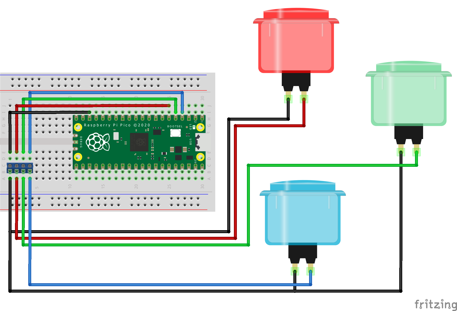
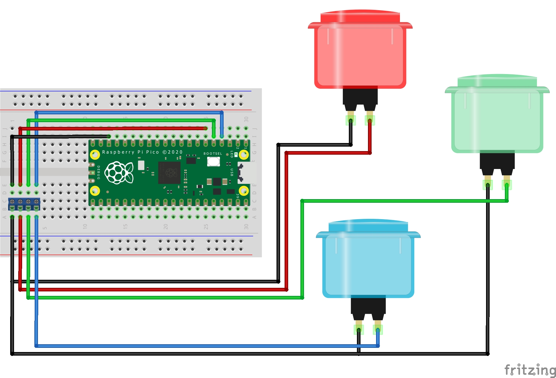
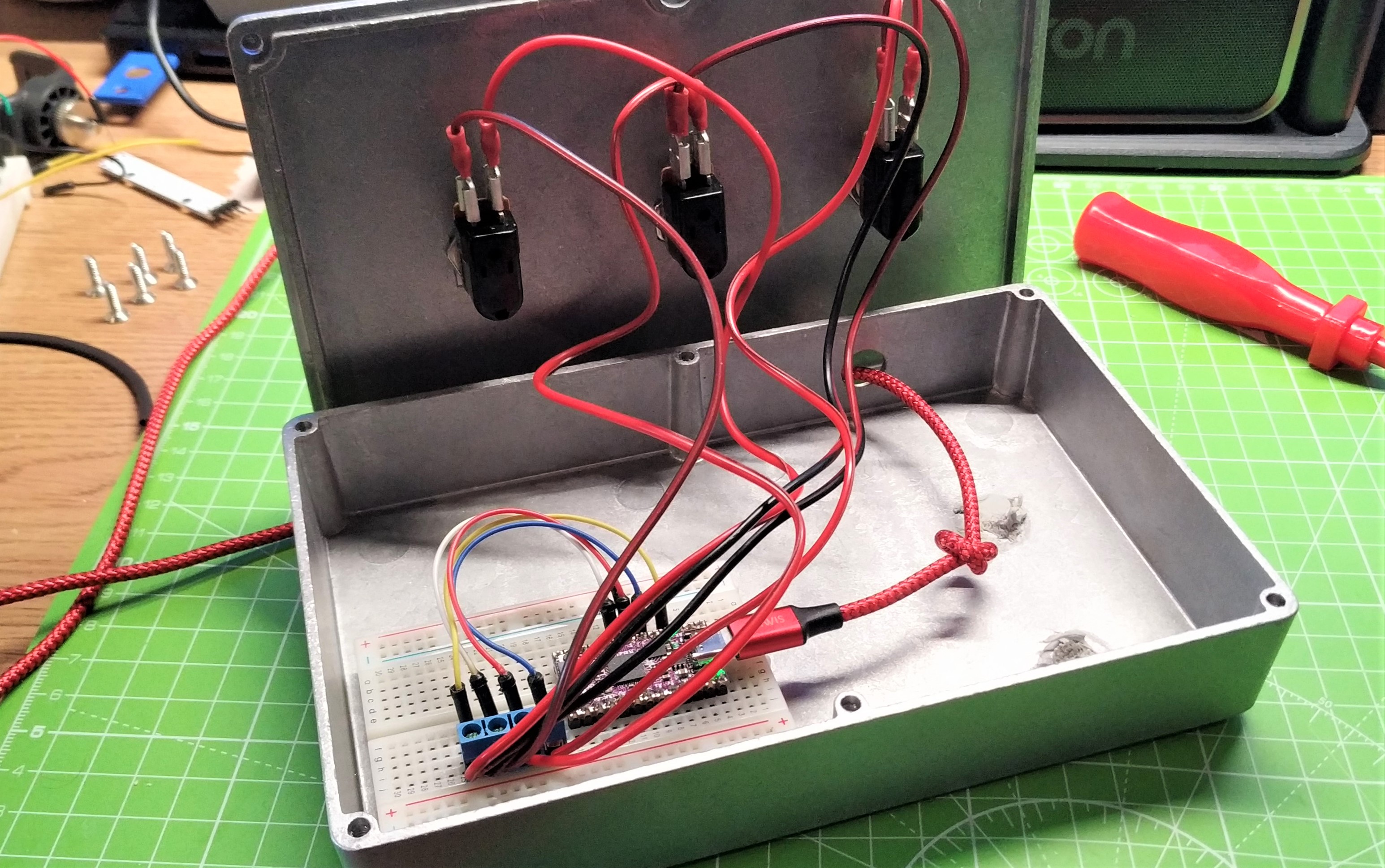
The circuit for this project is extremely simple. It uses three GPIO pins (2,3 and 4) and a common Ground (GND) connection. We connect the buttons to pins 2,3 and 4, then connect each button to a different GND pin on the Pico. All of the GND pins connect to a single GND, creating a common reference point.
Wiring and preparing the enclosure
Before we get into the details, here’s a word on safety. Soldering is a great skill to learn, but make sure that you are wearing suitable eye protection and that you solder in a well ventilated space. Drilling into plastic or metal will produce “swarf”, threads and bits of drilled material. Wear eye protection and double check your positions before you start the drill. Make sure that the enclosure is held firmly in place and always drill a pilot hole before drilling larger holes.
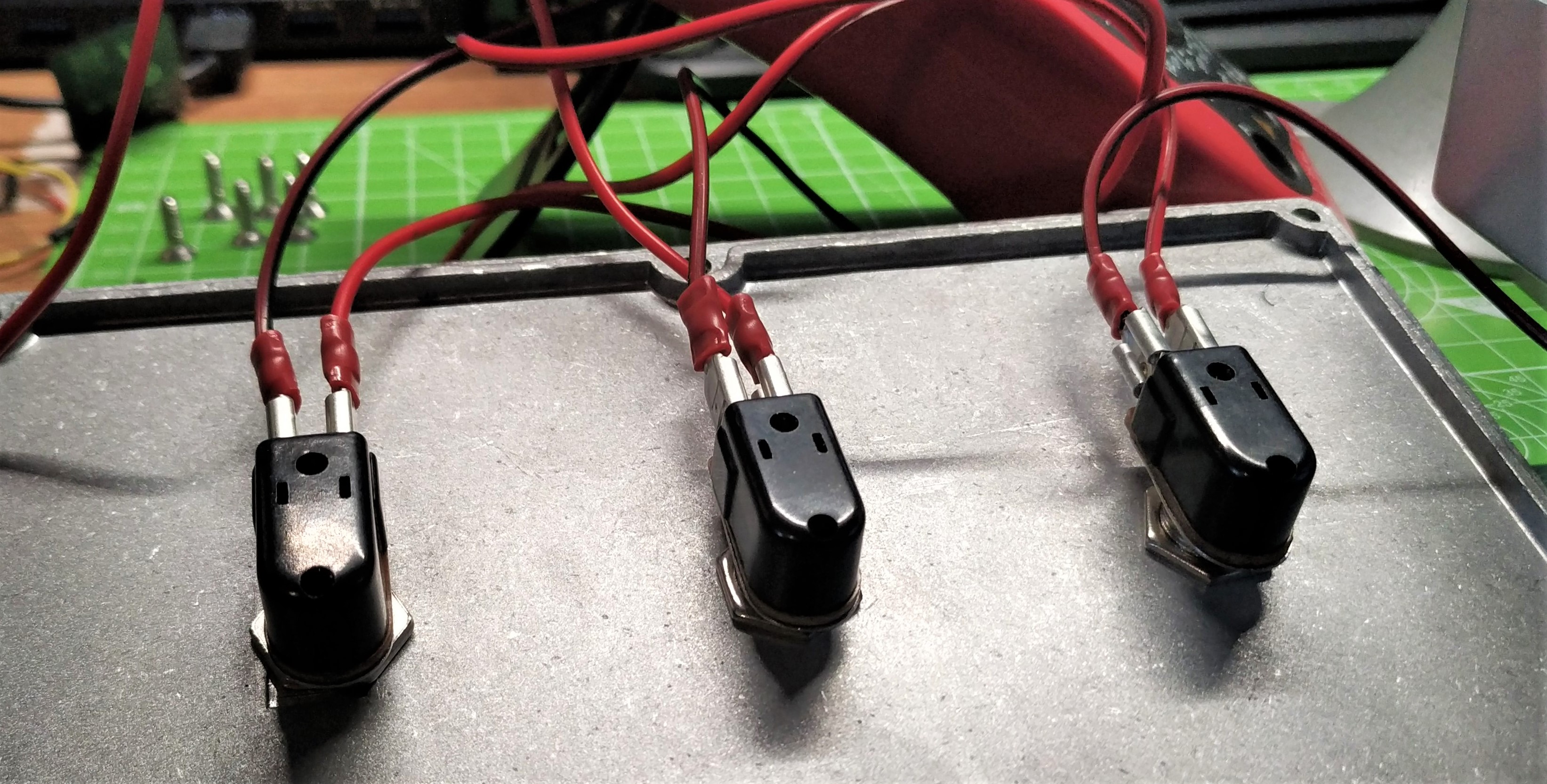
We chose to use momentary foot switches, commonly used in guitar pedals. They are designed to be stamped on and so stand the best chance of surviving the longest. Wiring is simple. They have no polarity, rather they make a connection when pressed. In this project they connect one side of the switch to a GPIO pin, pulled high using the Pico’s internal resistors to the other side which is connected to Ground (GND). By pressing the button we make the connection between the two sides, pulling the GPIO pin low and triggering a keypress.
We chose an alternative to soldering. Crimped terminals are a solder free method which uses friction to hold the wires in place. The crimps hold the wire inside a plastic sleeve. In the sleeve is a metal terminal. We squeeze the crimp using a tool and it locks the wire in place. The crimp terminal then slides onto the switch contacts. Crimps are quicker and easier than soldering, but they are an additional cost.
Get Tom's Hardware's best news and in-depth reviews, straight to your inbox.
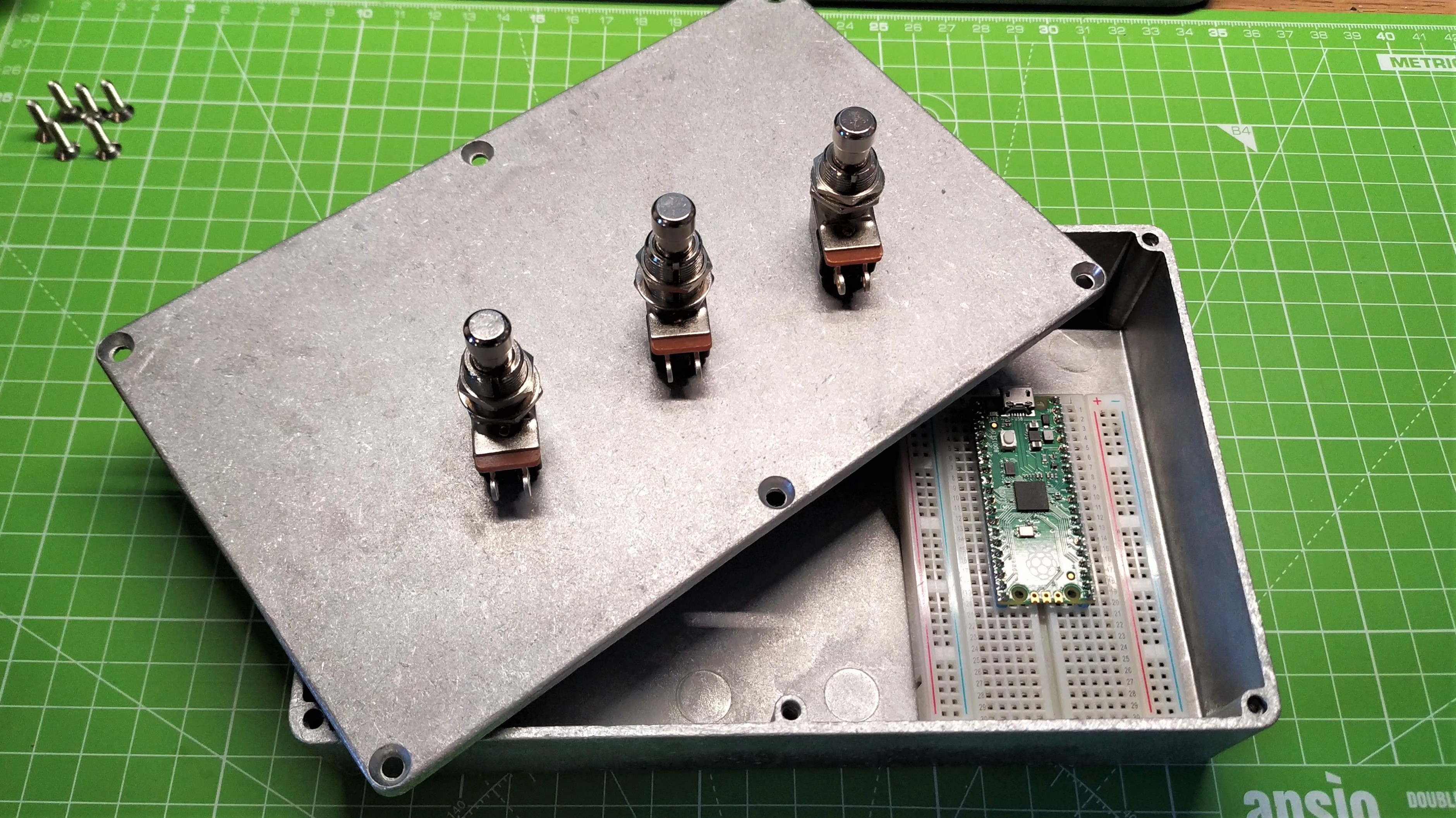
These switches need to be secured in a suitable enclosure. Typically we would use a plastic enclosure but unless we pay big money we are going to get flimsy plastic. Heavy duty ABS plastic cases can be found for around $10, but we opted for an aluminum enclosure, to match the industrial, heavy duty foot switch aesthetic.
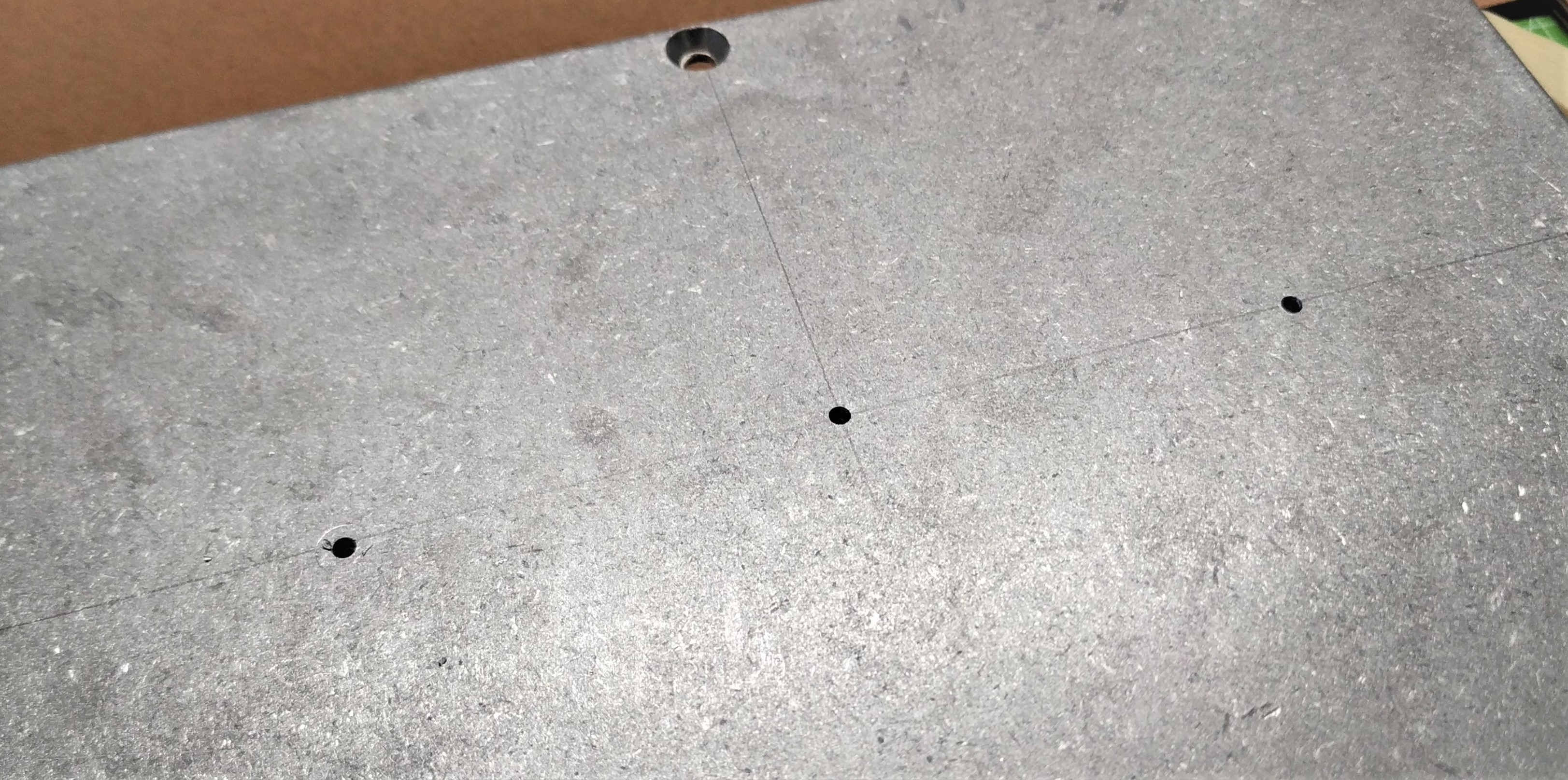
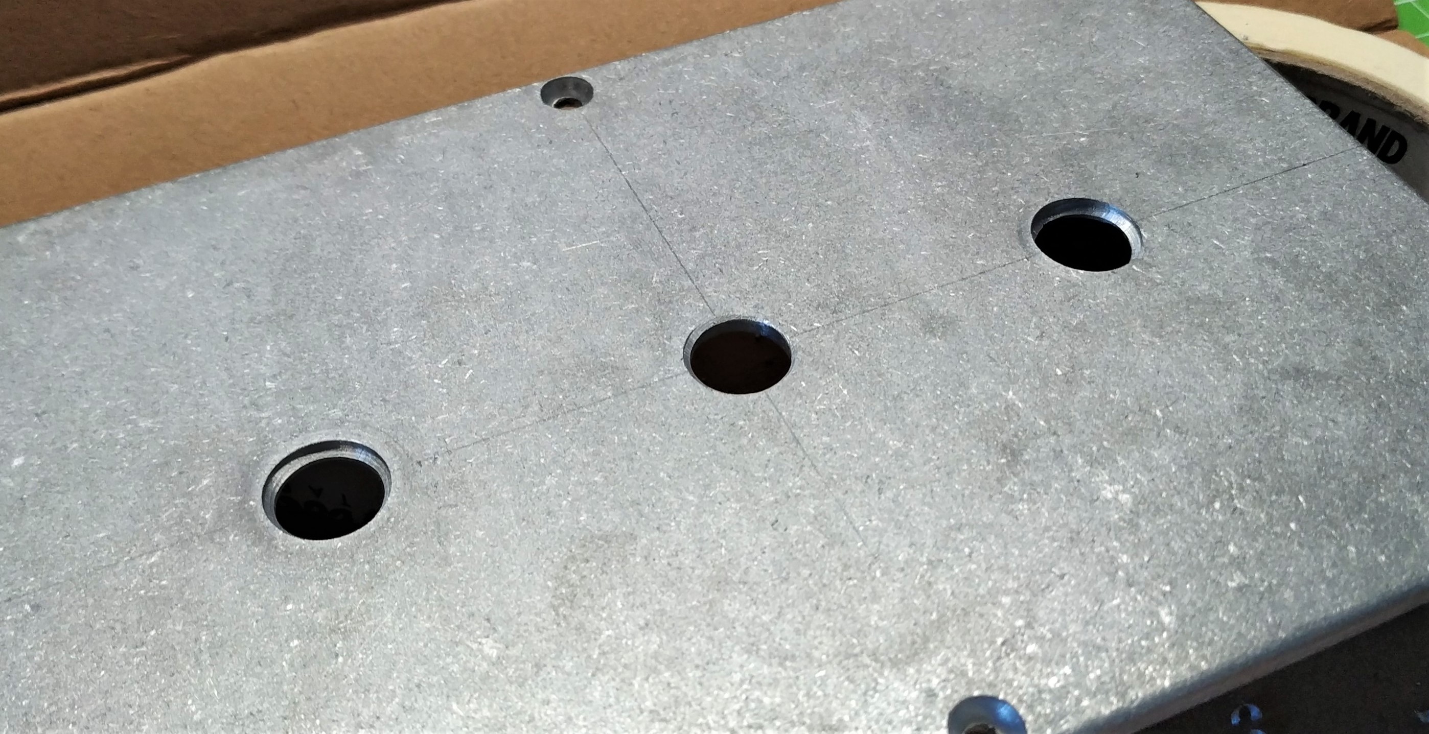
1. Measure three points on the lid of the enclosure and drill a pilot hole for each. We chose the dead center of the case as our starting point, then measured 5cm in both directions away from the center. In hindsight we would have moved further out, say 7cm and created a triangle of points instead of a line.
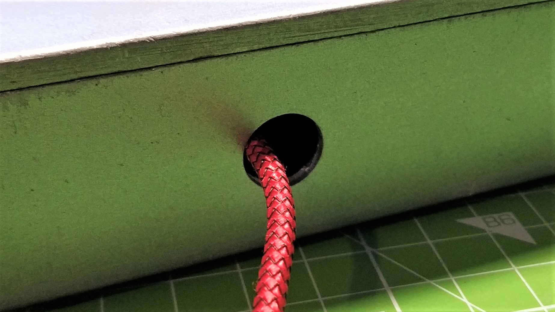
2. Move to the side of the enclosure and drill another pilot hole for the USB lead.
3. Swap to a larger drill bit and enlarge all of the holes. Do this a few times before moving on.
4. Swap to a stepped drill bit and then enlarge the three lid holes to match the diameter of the foot switch buttons. In our case we had 12MM switches, so used a piece of tape to identify the step on the drill bit.
5. Use a file to remove the sharp edges from the holes.
6. Use the stepped drill bit to enlarge the remaining pilot hole to match the size of the smallest end of your USB lead.
7. File the hole to remove any sharp edges. This is important for the USB lead as it will rub against the hole and may become damaged.
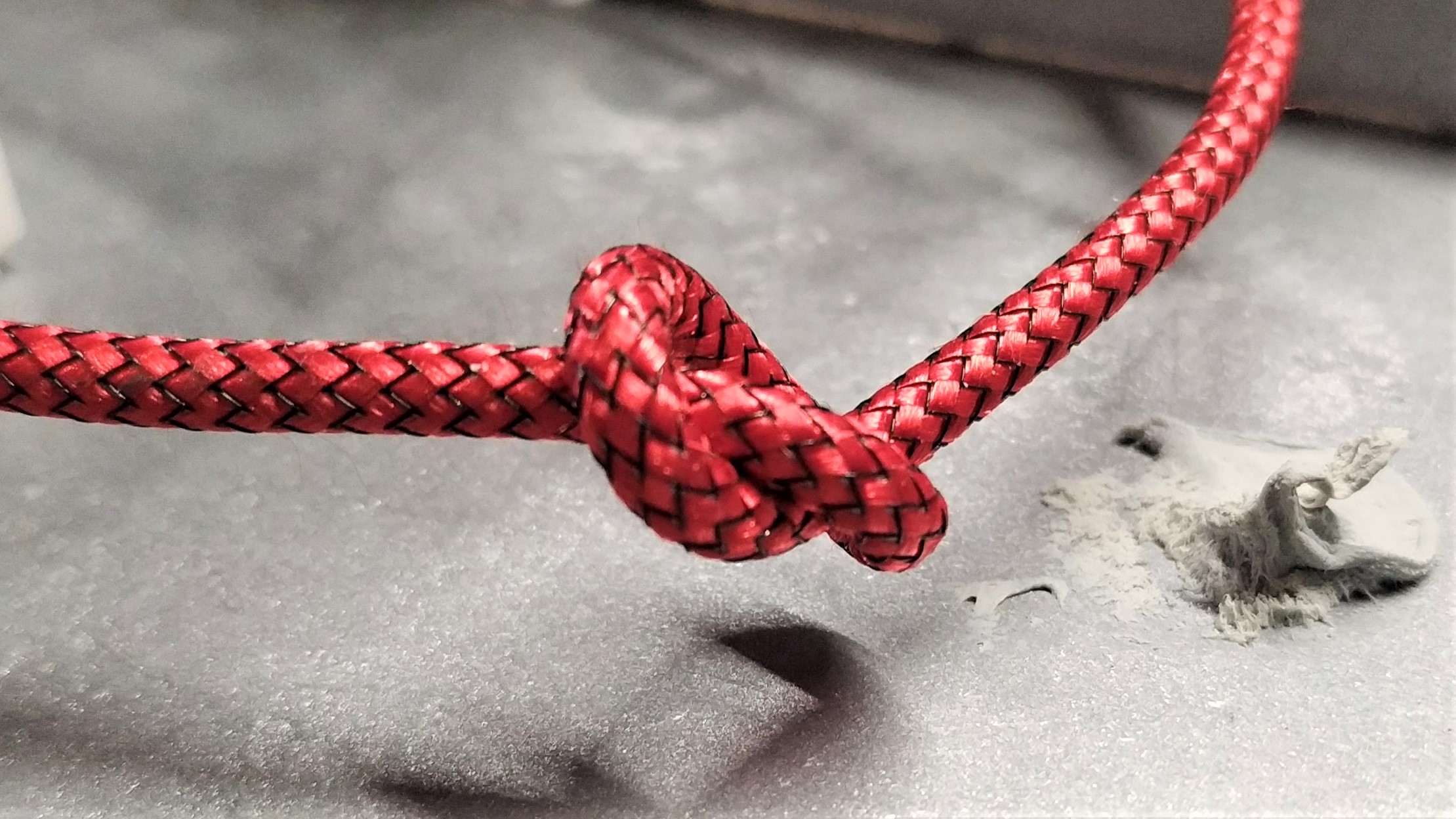
8. Thread a suitable USB lead through the hole, connect to your Pico and add a large knot to act as strain relief. The knot will reduce the risk of the USB lead being accidentally removed.
9. Secure the button wires to the screw terminal as per the circuit diagram.
You should now have all three buttons connected to the Raspberry Pi Pico via the screw terminal. Do not close the lid until the code is tested.
Install CircuitPython and libraries
Installing CircuitPython is extremely simple and Adafruit has a fantastic guide on how to do this. Follow Adafruit’s instructions to install the latest version.
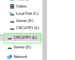
Our Raspberry Pi Pico now appears as a drive in the file manager. The drive is called CIRCUITPY and there we find a series of files and folders. Right now, we need to focus on lib. We need to download a ZIP file full of libraries, and install the correct files for our projects
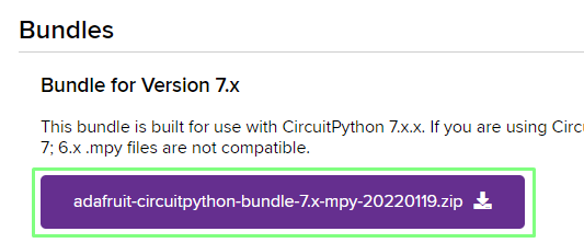
1. Download the latest bundle of libraries from the CircuitPython site.
2. Extract the files to your Desktop.
3. Copy the adafruit_hid folder from the extracted files to the lib folder on your CIRCUITPY drive.
Coding the Pico Pedal
1. Open the code.py file found in the root of the CIRCUITPY drive in your preferred editor.
2. Delete any code in the file.
3. Import two libraries to enable GPIO access. The first, board is a basic means to connect to the GPIO pins, the second provides a means to control the state of the pins.
import board
from digitalio import DigitalInOut, Direction, Pull
4. Import four libraries to emulate a US layout USB keyboard and keystrokes.The USB HID ((Human Interface Device) library enables our Pico to become a keyboard. The remaining libraries configure the keyboard to use a US layout and to use keycode to send keystrokes.
import usb_hid
from adafruit_hid.keyboard import Keyboard
from adafruit_hid.keyboard_layout_us import KeyboardLayoutUS
from adafruit_hid.keycode import Keycode
5. Finally import the time library. This library is used to add a pause to the code. This reduces the risk of accidental double keypressed (debounce).
import time
6. Create a keyboard object that will act as a USB HID.
keyboard = Keyboard(usb_hid.devices)
7. Set the layout to US.
keyboard_layout = KeyboardLayoutUS(keyboard)
8. Create a new object, one, to represent the first button on the pedal. This button is connected to pin 2 of the Pico.
one = DigitalInOut(board.GP2)
9. Using the one object, set the pin as an input, and pull the internal resistor up, so that the pin is high (on) at 3.3V.
one.direction = Direction.INPUT
one.pull = Pull.UP
10. Repeat the process for a second input. This time the variable should be connected to pin 3.
two = DigitalInOut(board.GP3)
two.direction = Direction.INPUT
two.pull = Pull.UP
11. Repeat again for a third input connected to pin 4.
three = DigitalInOut(board.GP4)
three.direction = Direction.INPUT
three.pull = Pull.UP
12. Create a variable, delay, to contain the amount of time that our code will pause for. Using a variable makes it easy to tweak the duration based on our requirements.
delay = 0.5
13. Create a loop to continually run our code.
while True:
14. Create a conditional test that will check the status of button one. If it is pressed, the button will connect the GPIO pin, 2 (which is True / HIGH), to Ground (GND) and change the state to False / LOW.
if one.value == False:
15. Add a print statement to show that the button press has been registered. This is a debug step which can be omitted, but we find it useful to prove that the code is registering a press as it eliminates one thing to debug.
print("Button 1")
16. Send a series of key presses. In our case we used CTRL + ALT + A, but you can change this to any key you wish and Adafruit has the list of all the keys you need.
keyboard.send(Keycode.CONTROL, Keycode.ALT, Keycode.A)
17. Release the keys. By doing this with no delay we restrict the key combination to a single key press.
keyboard.release_all()
18. Add a delay to reduce the chance of multiple keypresses.
time.sleep(delay)
19. Repeat the process for the second button.
   elif two.value == False:
       print("Button 2")
       keyboard.send(Keycode.CONTROL, Keycode.ALT, Keycode.B)
       keyboard.release_all()
       time.sleep(delay)
20. Repeat the process for the third button.
   elif three.value == False:
       print("Button 3")
       keyboard.send(Keycode.CONTROL, Keycode.ALT, Keycode.C)
       keyboard.release_all()
       time.sleep(delay)
21. Add an else condition to print “Waiting for button press” with a short delay before the loop repeats. The else condition is activated when no button is pressed.
  else:
       print("Waiting for button press")
       time.sleep(0.1)
Save the code to your Raspberry Pi Pico and CircuitPython will reload and run the code. Don’t close the case just yet!
Using Pico Pedal With OBS
Open Broadcaster Software (OBS) is a remarkable free streaming tool. With OBS we can stream live to YouTube, Twitch and many other platforms. We can also record videos for later editing. OBS uses Scenes to create different camera angles, screencasts and other video inputs.
We use a number of scenes for The Pi Cast, our weekly Raspberry Pi show. We have a scene for our front-facing camera, a scene for overhead cameras to show off a project, and a scene to show a stream of images or datasheets. To swap scenes we have a keypad programmed to move between them using shortcut keys. The Pico Pedal can be used in the same manner. You will need to have already created the scenes in order to create hotkeys for them.
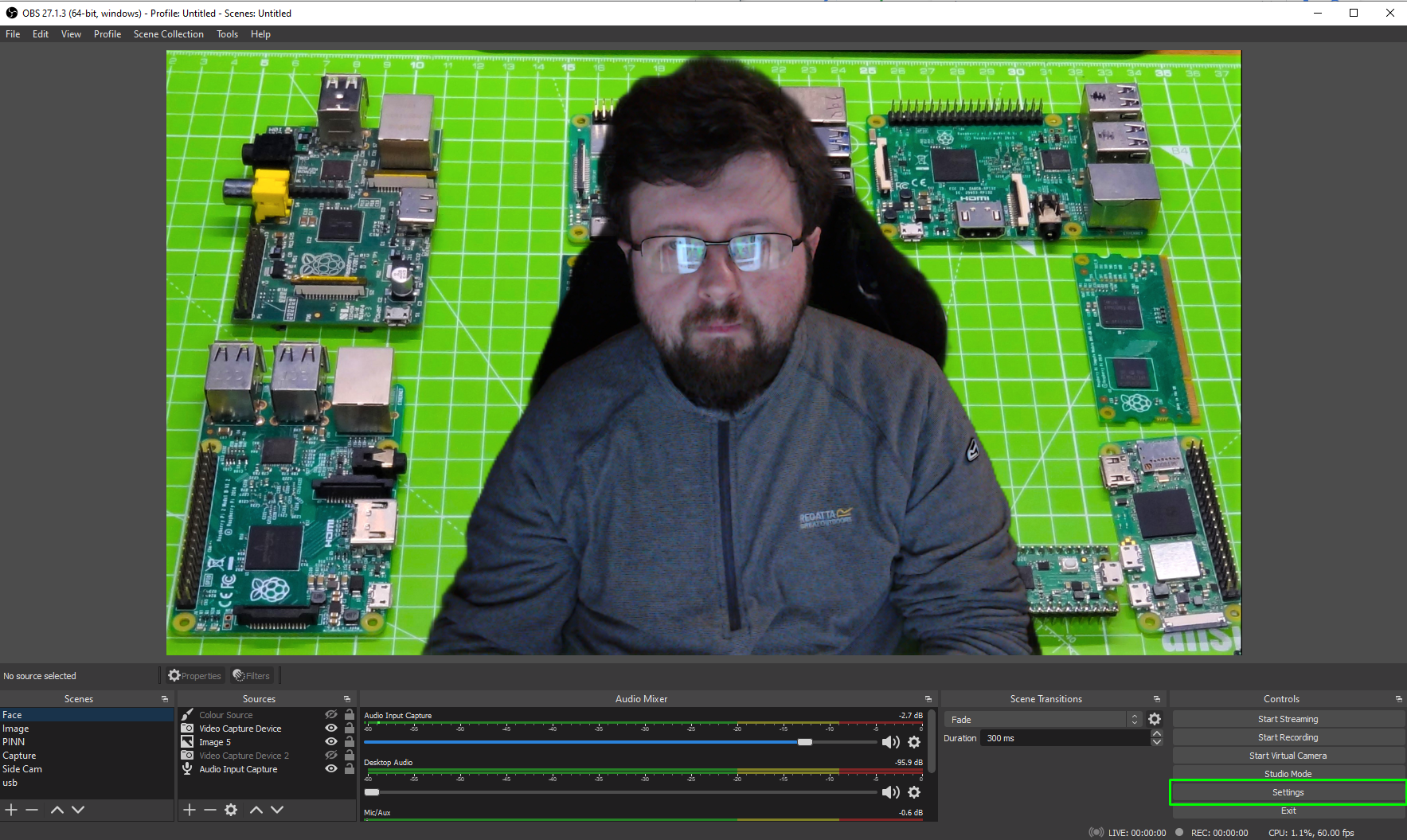
1. Open OBS and navigate to Settings, found in the bottom right corner.
2. Click on Hotkeys.
3. Scroll down to the scene that you wish to add a hotkey for. In our example we go to Face.
4. Click on the black box for Switch to scene.
5. On your Pedal press the button that you wish to assign to the scene. OBS will update to show that button press.
6. Click Apply and Ok to save the hotkey.
7. Repeat the process for the additional two buttons.
You now have the buttons of your pedal mapped to OBS, ready for your next stream. Now you can smoothly move from scene to scene without touching the keyboard.
Complete Code Listing
import board
from digitalio import DigitalInOut, Direction, Pull
import usb_hid
from adafruit_hid.keyboard import Keyboard
from adafruit_hid.keyboard_layout_us import KeyboardLayoutUS
from adafruit_hid.keycode import Keycode
import time

keyboard = Keyboard(usb_hid.devices)
keyboard_layout = KeyboardLayoutUS(keyboard)

one = DigitalInOut(board.GP2)
one.direction = Direction.INPUT
one.pull = Pull.UP

two = DigitalInOut(board.GP3)
two.direction = Direction.INPUT
two.pull = Pull.UP

three = DigitalInOut(board.GP4)
three.direction = Direction.INPUT
three.pull = Pull.UP

delay = 0.5

while True:
    if one.value == False:
        print("Button 1")
        keyboard.send(Keycode.CONTROL, Keycode.ALT, Keycode.A)
        keyboard.release_all()
        time.sleep(delay)
    elif two.value == False:
        print("Button 2")
        keyboard.send(Keycode.CONTROL, Keycode.ALT, Keycode.B)
        keyboard.release_all()
        time.sleep(delay)
    elif three.value == False:
        print("Button 3")
        keyboard.send(Keycode.CONTROL, Keycode.ALT, Keycode.C)
        keyboard.release_all()
        time.sleep(delay)
    else:
        print("Waiting for button press")
        time.sleep(0.1)

Les Pounder is an associate editor at Tom's Hardware. He is a creative technologist and for seven years has created projects to educate and inspire minds both young and old. He has worked with the Raspberry Pi Foundation to write and deliver their teacher training program "Picademy".
-
WalkingSilentz Firstly, thanks for this write up! It's given me a reason to buy some Pi Pico units and to get involved in CircuitPython finally.Reply
Unfortunately it's not working for me, when I run the script through Thonny, the Shell is outputting the following, did I do something wrong?...
Traceback (most recent call last):
File "<stdin>", line 12, in <module>
AttributeError: 'module' object has no attribute 'D2'
Thanks in advance! -
biglesp Hello, apologies this is because I was using a KB2040 for the project and forgot to change the pin reference.Reply
Use GP2 instead. The same applies for D3 (GP3) and D4 (GP4). I'll update the tutorial to show this.
Thanks
