Why Your Wi-Fi Sucks And How It Can Be Helped, Part 1
Omnidirectional, Not Omnipotent
We’ve covered a fair amount of bad news so far. There’s more. It’s time to discuss antennas.
We mentioned signal strength, but not signal direction. As you probably know, most antennas are omnidirectional. Like a ring of speakers blaring in every direction at once (with attached microphones receiving from all 360 degrees equally), omnidirectional microphones give you excellent coverage. It doesn’t matter where the client is located. As long as the client is within range, an omnidirectional antenna should be able to find and communicate with it. The downside, of course, is that the same omnidirectional antenna is also picking up every other source of noise and interference within range. Omnidirectional systems hear everything—good, bad, and ugly—and there’s very little you can do about it.
Imagine standing in a crowd, and you’re trying to talk with someone several feet away. You can barely hear someone over the ambient noise. What’s the natural thing to do? Cup a hand to your ear, of course. You’re trying to better focus the sound coming from one direction, while simultaneously blocking sounds coming from other directions, namely behind your hand. An even better sound isolator is a stethoscope. These try to block all ambient sound by plugging your ears, only allowing passing sounds carried through the flat chestpiece.
In the world of radio, the equivalent of a stethoscope is a technique called beamforming.
Beamforming Revisited
We covered beamforming in considerable depth during our prior visit with Ruckus, so we’ll only briefly review here.
The object in beamforming is to create a directed zone of heightened wave energy. The classic example of this is shown with water drops into a pool. If you were to hold two spigots over a pool of water and opened each spigot in just the right way that they released synchronized water droplets every so often, the concentric wave rings that flowed from each epicenter (where the droplets land) would create an overlapping pattern. You can see this pattern in the above illustration. Where the wave crests overlap, you have an additive effect, where the energy of both waves combine to create an even larger crest in the waveform. Because of the regularity of the drops, these amplified crests manifest in certain directions, forming a sort of “beam” of heightened energy.
The waves in this example are omnidirectional. They flow outward uniformly from the point of origin until reaching some opposing object or energy. Wi-Fi signals emitted from an omnidirectional antenna behave in the same way, outputting waves of radio energy that, when combined with waves from another antenna source, can create beams of heightened signal strength. When you have two waveforms in phase, the result can be a beam with nearly double the signal strength of the original wave.
Get Tom's Hardware's best news and in-depth reviews, straight to your inbox.
Omnidirectionality Harnessed
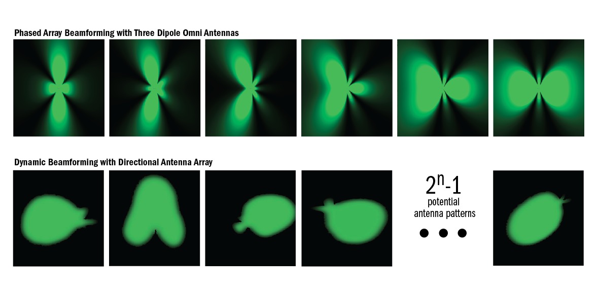
As the interference photo on the prior page shows, the beamforms from omnidirectional antennas project in multiple, and often opposing, directions. By modifying the timing of the signals from each antenna, one can control the shape of a beamform pattern. This is good because it focuses power in fewer directions. If your AP knows that its client is at three o’clock, does it make sense to send a beam to nine o’clock or 11 o’clock? Well, yes...if having that wasted beam is unavoidable.
In fact, with omnidirectional antennas, this waste is unavoidable. Technically speaking, what you’re seeing in this top row is the result of a phased array, a group of antennas in which the relative phases of the respective signals feeding the antennas are varied in such a way that the effective radiation pattern of the array is reinforced in a desired direction and suppressed in some undesired directions. It’s a bit like squeezing the middle of a partially inflated balloon. When you tighten your grip, you can make part of the balloon pop out dramatically in one direction, but you also get a corresponding surge in a different direction. You can see in the image above how the top row showcases different beamform patterns generated by two dipole omni antennas.
A Beamforming Correction
Obviously, you want a beamform to cover your client. With phased array beamforming, as illustrated in the top row images above (this time shown with three dipole antennas), the AP analyzes signals from the client and uses algorithms to alter the emitting pattern, thus changing the path direction to better target the client. These algorithms are computed in the AP’s controller, which is why you sometimes see the process referred to as “chip-based beamforming.” The technique is also commonly called transmit beamforming by Cisco and others, and it remains an optional, if widely unimplemented, component of the 802.11n specification.
Chip-based, phased array beamforming is the method used by most vendors who currently advertise beamforming support. It is not the method used by Ruckus. In this regard, I erred in my prior article. On page six, I stated that “Ruckus uses ‘on-antenna’ beamforming, a technology developed and patented by Ruckus ... [that] uses an array of antennas.” This is not the case. Phased array beamforming involves multiple antennas. Ruckus’ approach does not.
Ruckus can beamform on each antenna independent of the other antennas. This is done by strategically placing metal objects in the vicinity of each antenna within an antenna array to independently affect its radiation pattern. We’ll delve a little deeper into this shortly, but you can see some of the different types of beamforming patterns generated with Ruckus’s approach on the second row of images above. Looking at these two side by side, there’s no way to tell which will yield the best real-world performance. Triple-antenna phased array beamforms appear more focused than Ruckus’ relative coverage blobs. Intuitively, one might assume that the more focused the beam, the better the performance, all other things being equal. It’ll be interesting to see if this plays out in our test results.
La-La-La…Not Listening!
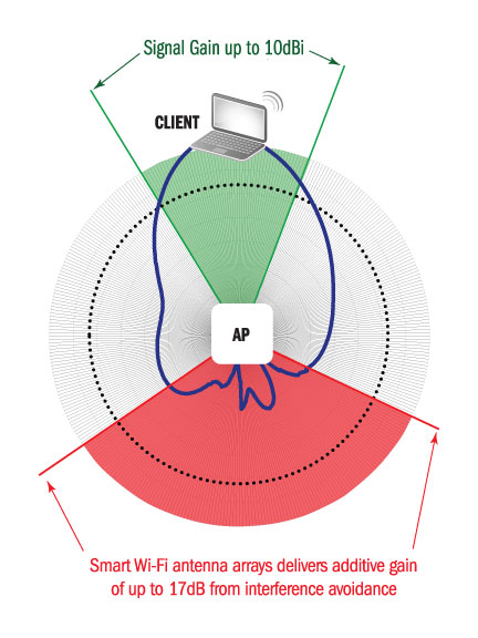
Remember the effect of cupping a hand behind your ear? Cutting interference from an unwanted direction can improve reception quality, even though the client hasn’t changed its signal output. According to Ruckus' numbers, simply ignoring signals from the opposite direction as the client can result in up to 17 dB of additive signal gain due to interference avoidance.
At the same time, the improvement in forward signal strength due to beamforming can yield an additional 10 dB of signal gain. Given the previous explanation about the impact of signal strength on throughput, you can start to see why beamforming can be so important and why it’s such a shame that most of the wireless market has ignored these techniques so far.
Spatial Multiplexing
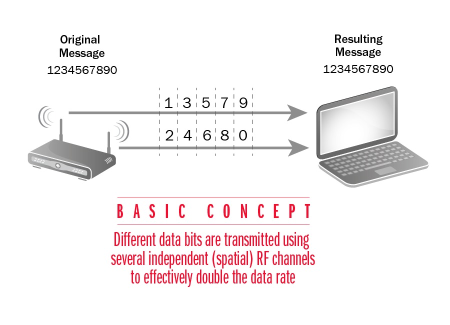
One of the main enhancements in the 802.11n specification was the addition of spatial multiplexing. This involves using the natural fracturing, so to speak, of one primary radio signal into sub-signals that arrive at the recipient at slightly different times. If you picture an access point at one end of a gym and a client at the other end, a straight radio path down the center of the gym will take slightly less travel time than a signal bounced off the side wall. There are usually multiple possible signal paths (spatial streams) between wireless devices, each of which can carry a different data stream. The recipient takes these sub-streams and recombines them. This process is sometimes called link diversity. Spatial multiplexing (SM) tends to work very well indoors, but terribly in less boxed-in environments like open fields, because there are no objects for signals to bounce off of in order to create a sub-stream. The bottom line is that, when it can be implemented, SM serves to increase channel bandwidth and improve signal-to-noise ratios.
To visualize the difference between SM and beamforming, imagine a two buckets—one filled with water (data) and the other sitting empty. We want to move the data from one bucket to the other. Beamforming involves having one hose connecting the two buckets, and we’re increasing the water pressure in order to move the fluid more quickly. With SM, we have two (or more) hoses moving water with the usual amount of pressure. With a single radio chain, meaning one transmit radio linked to one or more antennas, SM typically outperforms beamforming. With two or more radio chains, the opposite is often the case.
Can You Do Both?
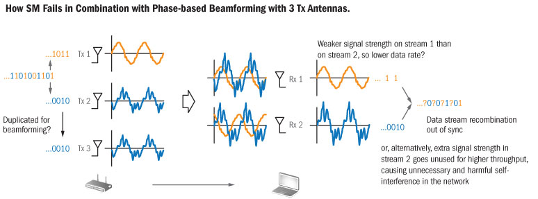
I’m not crazy about this image, but it tries to explain why you can’t combine spatial multiplexing and beamforming with a three-antenna design, which is what we have in many access points today. Essentially, if two antennas are tied up doing beamforming of a first stream, that leaves one antenna left to run a second stream. You might think that with two incoming streams, SM should be no problem. However, the beamformed stream is likely to have a much faster data rate—so much faster that the receiving client can’t synchronize the two streams effectively. The only way to bring these two streams close enough in data rate for synchronization is to drop the power in the beamformed stream...which sort of kills the whole reason for beamforming in the first place. You’re left with two “standard pressure” streams, to reuse our former illustration.
What if you had four antennas? Yes, that would work. Two would handle beamforming and the other two would tackle SM. Naturally, adding another antenna increases cost. In the enterprise AP world, buyers might readily absorb the upcharge, but consider the client, which would also need four antennas. We only recently got three antennas in notebooks, and that was a battle. Where would the fourth go? Perhaps more importantly, what would it do to power consumption? In the absence of answers and/or enthusiasm from the market, vendors have held off on pursuing four-antenna designs.
Antennas And Radios
We used the term “radio chain” earlier, but this doesn’t provide sufficient depth or accuracy in many cases. There’s a proper notation for the relationship between radio chains and spatial streams that is important to note as you assess wireless gear.
Consider the term 1x1:1. Yes, I keep hearing technical experts pronounce this as “one by one colon one.” Really? We can’t find a better expression than colon?
The 1x1 refers to the number of transmit (Tx) and receive (Rx) radio chains. The :1 refers to the number of spatial streams being used. Thus an industry standard 802.11g access point would be 1x1:1.
The 300 Mb/s rate specified in most of today’s 802.11n products depends on two spatial streams. These are 3x3:2 products. Perhaps you’ve seen a few 450 Mb/s designs floating about. These are 3x3:3, but despite the 450 Mb/s theoretical rate, there’s very little if any benefit over 3x3:2. Why? Because, again, you can’t effectively combine beamforming and spatial multiplexing on three radios. Instead you have to run three streams at standard strength, which, as we’ve seen, limits range and leaves packets more susceptible to resends. This is why 450 Mb/s routers continue to flounder at the mass market fringe. Under perfect conditions, 3x3:3 would be better, but we don’t get to live in a perfect world. Instead, we have one filled with contention and interference.
SRC Versus MRC: Can You Hear Me Now?
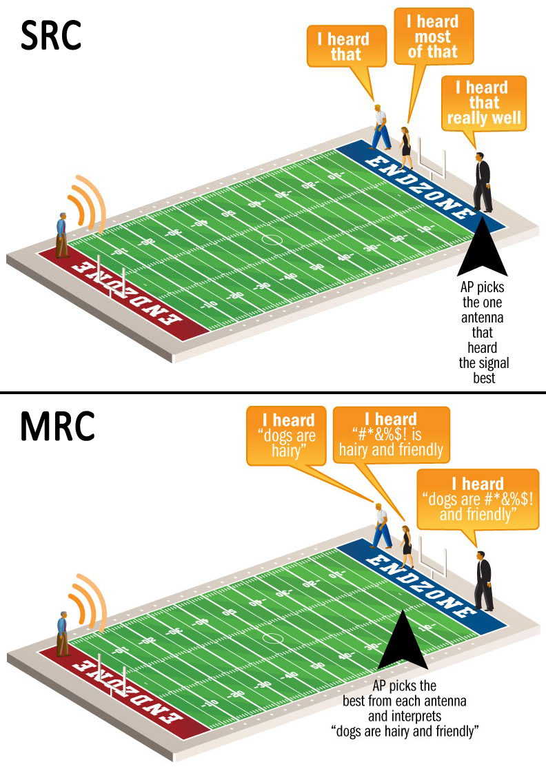
Listening is obviously key for effective communication, and how you listen matters. As in our illustration, if you have someone talking at one end of a field and three people listening at the other end, odds are that the listeners, for whatever various reasons, will not hear exactly the same thing. In wireless communication, you can ask, “OK, which of you three receivers heard what that transmitter said the best?” Whichever receiver seems to have heard the most is selected. This is called simple ratio combining (SRC), and it’s closely related to the idea of antenna switching, wherein whichever antenna has the best channel gain is used.
A more effective and widely used approach with multiple antennas is maximal ratio combining (MRC). In the most basic terms, this involves the three receivers putting their heads together and comparing notes to arrive at a consensus opinion of what was said. With MRC, the client enjoys better wireless coverage and improved quality of service. The client is also less sensitive to exact antenna location.
Of course, this begs another question: if three antennas beat two, then...
Why Not Use A Million Antennas?
...why not use a gajillion antennas?
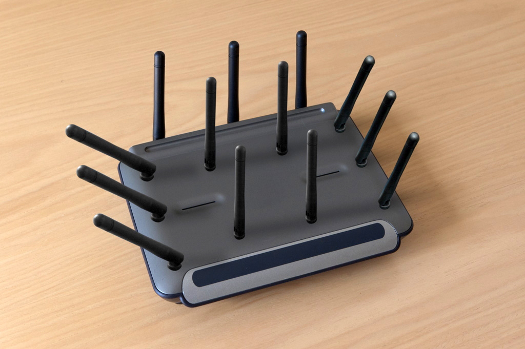
Aesthetic issues aside, the real reason we don’t have porcupine APs like this one has more to do with the law of diminishing returns. Test data shows that the jump from two antennas to three is not as great as from one to two. Again, we go back to the problems of cost and (at least on the client side) energy consumption. With omnidirectional antennas, the consumer market has settled on three as the sweet spot for antenna counts. In the enterprise world, you may find more, but typically not many more.
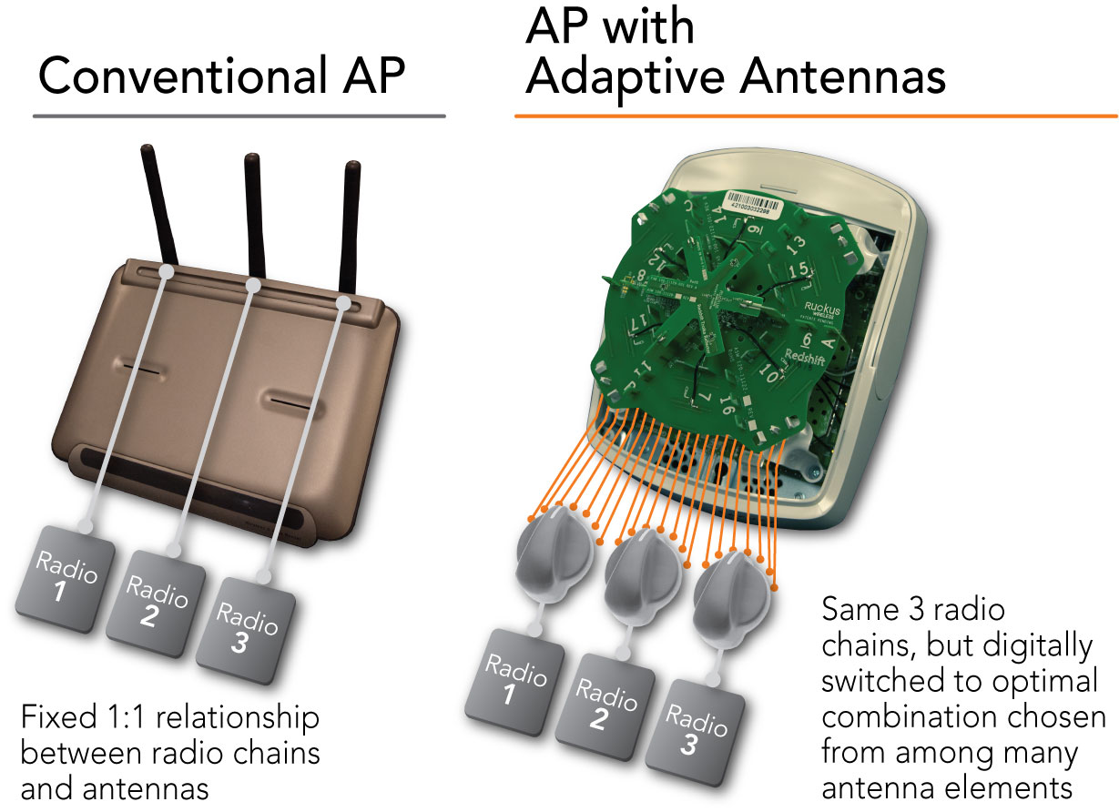
Ruckus is one of the few exceptions in this case because it uses directional antennas. In the circular access points you’ve seen in this article’s images, the disc-shaped platform houses 19 directional antennas. Collectively, the coverage zones of these 19 encompass a full 360 degrees. Nineteen omnidirectional antennas would be absurd, but 19 directional antennas (or some similar number, depending on the AP design) can provided the gain benefits one would expect from higher antenna counts yet still consume a fairly low amount of power since only a few of the antennas are likely to be in use at any given time.
-
iamtheking123 Really TH, you think I'm going to click next 27 times and Read more another 27 times? Sorry, but I'll read this when it is put on one huge page.Reply -
lunyone Where's the usual "jump to this section" that usually is with Tom's articles/reviews? I have a hard time clicking for 27 times too, but would prefer a click down menu to select the topics that most interest me or to at least have the option to jump ahead, if I so desired.Reply -
cmashwin Dear THG.. it really is a big hassle clicking 10 buttons dat dont load fast enough to read five lines.. R u worried abt copyright thingy? pls pls give us an easy to read comprehensive page to read ur wonderful articles and dont make it difficult.. As an eg, to read dis article, I had to load it in 2 different browsers n click 54 times!! come on give us a break!!Reply -
proxy711 Really? hes just trying to avoid a wall of text. i don't see the big deal. Thanks for the article.Reply -
Why does every page require us to hit Read more to see the full text? Do you think most people who read this article will prefer to only read the first 1/3rd of every page?Reply
-
openi3 I believe I know why this article was written like this... the salesmen that need to know this need you to draw them a picture....Reply
Hang around the wireless router/dsl section of your local PC hardware store and listen to the stories...
My favorite one was where two kids persuaded their mom that they needed a $120 wireless range booster for the grandmother's notebook which was in a tricky part of their property to reach. How about giving them a $5 phone cable and a better access point for $30... -
bellman80 *Why Your Article Layout Sucks And How It Can Be Helped*Reply
Just read all the comments above. I know it's free content and I actually like the article, but you should really take a look at all the feedback you are getting.

