APC BR1000G Tear-Down
Mask Off
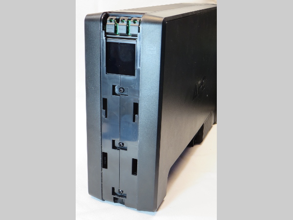
The BR1000G doesn't look as sexy with its face bitten off, which makes me glad I managed to salvage the makeup job I'll reapply later.
How many hidden screws do you see? Three? That’s what I thought too, until I tried prying it apart and realized that there was a fourth one hidden between the leftmost two buttons up top.
MORE: APC BN650M1-CA Tear-Down
MORE: APC BGE90M-CA Tear-Down
MORE: APC BE550G Tear-Down
First Peek
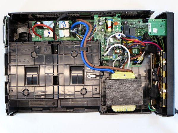
Similarities with the BX1000 end here. Instead of an HVDC stage followed by an output bridge and a separate AVR auto-transformer, the BR1000G has an AVR transformer driven directly from battery voltage to generate the AC output. APC ran out of space to fit all of its functionality on the main board and had to go with a mezzanine arrangement.
Terminal To Nowhere
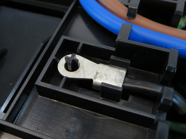
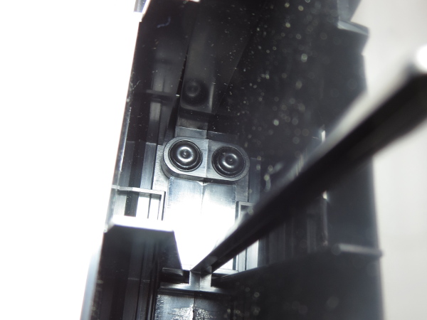
This grabbed my attention upon removing the cover: what is a wire with an eyelet crimp connector doing attached to a plastic pin on the side of the battery compartment?
Making Sense
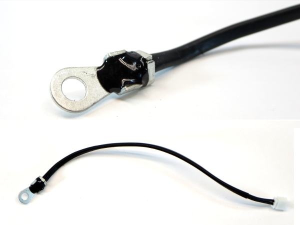
After digging everything out of the UPS’ body, it turns out that this wire is actually two wires with a long piece of heat-shrink tubing on top. The eyelet terminal was used merely to increase the temperature sensing element’s effective surface area. As far as I can remember, this is the first time I have opened a UPS equipped with battery temperature monitoring.
Staked
While the top, bottom, and inner sides of the battery bay are screwed to the bottom/left half of the housing, the rear is permanently attached by welding the plastic stakes or stems to the bay. It seems odd to go through the trouble of setting up a plastic (fiber-reinforced ABS) welding station and then only using it for two out of six attachment points between the same two pieces.
Get Tom's Hardware's best news and in-depth reviews, straight to your inbox.
Fan Not Included
Between the iron core transformer and mezzanine board, there is a vacant 40 millimeter fan holder molded into the side of the battery bay. Does this mean that a fan was originally planned but ultimately found to be unnecessary, or are the molds shared with a different product that does require a fan?
There's also an unpopulated three-pin connector labeled “J25” next to the two current-sensing transformers, which coincidentally carries the “FAN” function name on its perimeter. Smells to us like APC is reusing the exact same boards for the 1300 and 1500 VA models, give or take a few component additions, substitutions, and firmware modifications.
Breaker
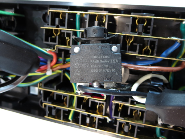
If you guessed that there would be a 15A breaker behind the rear panel, you were correct.
There's a mess of wires back there. The master outlet requires its own line for current sensing, and the master-controlled outlets also require separate wiring. As a result, we find a total of 10 wires between the outlet strips and main board. Thankfully, all wires have connectors and all connectors are labeled by wire color on the main board.
Outlet Strips
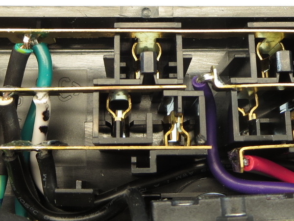
One last attribute the BR1000G carries over from APC's BX1000 is its ground contact strips: instead of simple bent flaps or torque fingers, they get the same pinchy finger treatment as the live and neutral strips (albeit with a smooth arc shape instead of straight bends). That’s how proper ground strips should be made.
RF Surge Protection
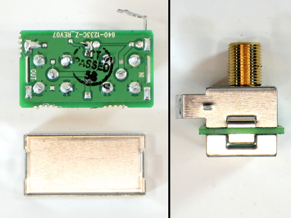
In one of my SurgeArrest Performance tear-downs, I commented on the lack of shielding behind the RF surge protection module. APC responded that its design met the requirements without a shield. Here, though, the RF module does have a small shield that clips to the front part through two thin slots in the PCB.
There isn't much circuitry underneath; the signal trace goes almost straight from input to output. We find what must be the leads of a TVS diode or equivalent device under the top shield and a trace width change in-between on the bottom layer.
Ethernet Surge Suppression
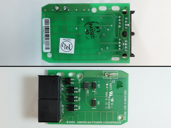
Doesn’t that look like a cute little board? Instead of using 16 discrete 1N4007 diodes as we've seen in the past, this one uses four Fairchild MB1Ses (100 V, 0.5 A forward current, 35 A surge) for steering surges around the circuit; an ST-branded component with an unreadable model number that could be a zener, SIDAC, or DIAC type device; and a pair of S2MA diodes (1 kV, 1.5 A) isolating the Ethernet circuit from ground. There is also a spark gap cutely labeled “GDT1”.
For a network surge to get shunted to ground, it has to exceed the S2MA diodes’ 1 kV breakdown voltage and the spark gap’s ~700 V.
-
bit_user Thanks for this.Reply
BTW, if you setup a kickstarter for funding your reviews, I'll bet you'd get lots of donations. I'd certainly chip in. -
Zaxx420 Am a regular reader of ur UPS teardowns here at Tom's...having a backround in "EEE", I find them very interesting to say the least. I have an older APC BACK UPS RS-1500 that needs a new battery. B4 I spend on a new batt was wondering if you've reviewed any APC 1500VA 'home' units? Are they decent or should I look at a newer unit instead of a fresh batt?Reply -
Daniel Sauvageau Reply
If your RS-1500 is from ~2005, look for my APC BX1000 tear-down. Based on how the BX1000's battery cover says XS1000 and the firmware version says RS1000, I suspect that the RS1500 will be practically the exact same thing except for having that third FET location on the heatsink plates populated and a larger HVDC transformer..18676443 said:I have an older APC BACK UPS RS-1500 that needs a new battery. B4 I spend on a new batt was wondering if you've reviewed any APC 1500VA 'home' units? Are they decent or should I look at a newer unit instead of a fresh batt?
-
Daniel Sauvageau Reply
Glad you liked it.18676391 said:Thanks for this.
BTW, if you setup a kickstarter for funding your reviews, I'll bet you'd get lots of donations. I'd certainly chip in.
For Kickstarter, I do not think a platform where I need to meet a goal to get funds would work too well. Patreon might be more appropriate for my use: contribute monthly, piece-wise or one-off to help me get what I need, when I need it.
-
bit_user Reply
Good point. I'm just thinking of some way that people can chip in to buy you equipment to test. Any extra you might use to fund your time + maybe you can ebay some of the re-assembled units, when you're done. Perhaps it can be setup for people to vote on different models with their contributions, if patreon has a way of creating different projects for people to contribute towards.18677660 said:Patreon might be more appropriate for my use: contribute monthly, piece-wise or one-off to help me get what I need, when I need it.
Personally, I'm interested in higher-end UPS models and AV powerline filters (like those from Panamax).
-
WFang Yes, a Patreon option would certainly be interesting way to get funds for higher end UPS and powerfilters!Reply -
alextheblue Reply
I'd slap a battery in it if I was you. I mean, you're already got the unit. If it had some other failure or you were lacking a UPS but in the market for one, the BR1500G is probably the best in it's price class. I've got one - if you tear it open it's going to look pretty similar to the BR1000G in this tear-down. It does have a fan which it fires up whenever it's on battery. Again, very decent unit for the money, but it's not going to be built quite up to the standards of the older units. In actual use though this thing has been kick-ass - I needed something with enough oomph to sustain my system for a bit if I lose power while gaming. Gives me time to gracefully exit the game and finish anything I needed to do.18676443 said:Am a regular reader of ur UPS teardowns here at Tom's...having a backround in "EEE", I find them very interesting to say the least. I have an older APC BACK UPS RS-1500 that needs a new battery. B4 I spend on a new batt was wondering if you've reviewed any APC 1500VA 'home' units? Are they decent or should I look at a newer unit instead of a fresh batt?
