Apple 5W Adapter Knock-offs: The Colorful A1265 Tear-Down
Bottom Of The Barrel. Hopefully.
More than one decade ago, Apple introduced its A1265 compact 5W AC adapter. As with most high-margin convenience goods, countless cheaper imitations of varying quality flooded the market over time. But the media's focus on unsafe adapters only peaked in the year following the electrocution death of nurse Sheryl Aldeguer in April 2014.
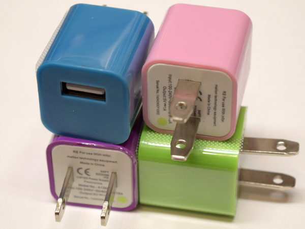
Has the safety of generic adapters improved over the past few years, or are we just more fortunate? Dredging what is hopefully the bottom of my AC adapter barrel, the $6 Colorful four-pack (that's $1.50 per brick) gets the honor of heading today's feature.
MORE: 10 Inexpensive Automotive USB Adapters Tested
MORE: Best Deals
Spotting A Fake
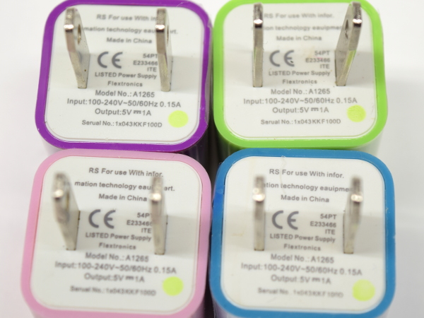
A real Apple A1265 announces itself with “Designed by Apple in California,” followed on the next lines by the model number and electrical specifications, with a “For use with information technology equipment” note at the bottom.
Here, those two blocks got swapped, while the “Designed” bit is omitted altogether and “equipment” gets misspelled “eauipment.” Also, instead of the UL mark between its prongs, we see a CE (European Conformity) mark that is completely out of place on a NA-style plug and therefore fake. Should we find this sad or hilarious? At least it does have the merit of making this set of fakes readily identifiable as such.
MORE: 10 Inexpensive Automotive USB Adapters Tested
Get Tom's Hardware's best news and in-depth reviews, straight to your inbox.
MORE: Best Deals
Popping Open
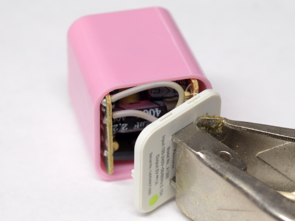
Some of Apple’s early versions of its genuine adapters had a tendency to split open or lose prongs when pulled out of power outlets. On a genuine adapter, the green dot identifies updated designs that address this flaw.
Popping the prong cap away from the adapter’s housing required considerably more force than I would deem acceptable to apply to a power outlet, which makes the pull-apart ‘test’ a pass: it shouldn’t come apart any time soon from normal use.
MORE: 10 Inexpensive Automotive USB Adapters Tested
MORE: Best Deals
PCB Top
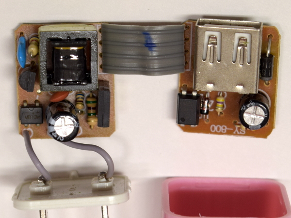
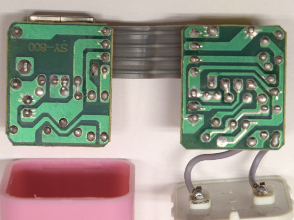
A first look from the top reveals what appears to be a minimalist two-transistor setup split between two small boards. You might think that the two boards are functionally separated between primary and secondary side for safety reasons. However, the optoisolator’s presence on the output board is a clear indication that mains-referenced voltages must be going over the ribbon cable. An additional cause for concern is the lack of a fuse on the input, which means the wires or circuit board traces will burn out should the circuit fail. And an uncontrolled failure could degenerate into a fire hazard.
MORE: 10 Inexpensive Automotive USB Adapters Tested
MORE: Best Deals
PCB Bottom
What do we find on the board's back? Decent soldering, no surface-mount components, almost no separation between the primary and low-voltage sides, and no anti-tracking slots to prevent a permanent path from forming where static discharges are most likely to occur across the isolation boundary.
With a layout like this, it is painfully obvious why folks keep getting shocked by aftermarket “A1265” adapters.
MORE: 10 Inexpensive Automotive USB Adapters Tested
MORE: Best Deals
AC Board Top
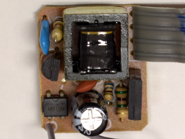
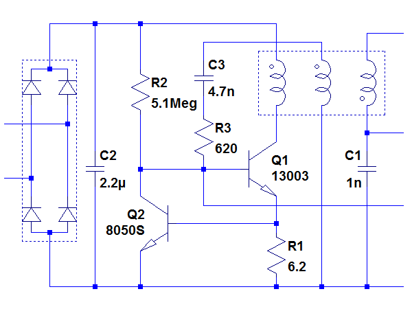
How many components are on the AC side of things? Three resistors, two ceramic capacitors, one electrolytic capacitor, one diode bridge, a 8050S 20V/700mA NPN transistor, an MUE13003 400V/1.5A NPN transistor, and the transformer. A 5.1MΩ resistor provides base bias to the 13003, while a 680Ω resistor and orange ceramic capacitor limit the oscillator’s positive feedback current. Lastly, the 6.2Ω resistor provides current sensing on the 13003, which drives the 8050S acting as a current limiter.
Sounds complicated? Perhaps it’ll be easier to digest in schematic form after taking a closer look at the bottom.
MORE: 10 Inexpensive Automotive USB Adapters Tested
MORE: Best Deals
AC Board Bottom
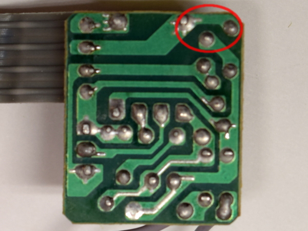
Whoever designed this board appears to love removing small lines of solder mask around pads. I find it funny that this individual went through the trouble of adding solder to traces when those traces normally carry less than 100mA and aren’t connected to heat-generating components. Even funnier is that the bottom beefed-up trace ends on a non-connected pad, while the one above it feeds the 5.1MΩ resistor.
Safety-wise, the area of greatest concern is the red ellipsis where clearance between primary and low voltage is merely a millimeter. There should be an anti-tracking slot there, at least.
MORE: 10 Inexpensive Automotive USB Adapters Tested
MORE: Best Deals
AC Board Schematic
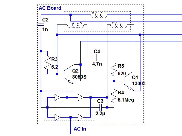
Here’s the schematic I put together by reverse-engineering the board while preserving the general component locations and trace layout. Following Q1's emitter, you see it go to circuit negative through the 6.2Ω resistor, which is also connected to Q2’s base. That transistor's collector, in turn, is connected to Q1’s base. If you know how an NPN transistor works, you can see how enough current through R3 will cause Q2 to dump some of Q1’s base current to negative and limit its collector current. Such a scheme is necessary to prevent Q1 from instantaneously self-destructing should the transformer momentarily reach saturation for any reason and limit its power draw.
MORE: 10 Inexpensive Automotive USB Adapters Tested
MORE: Best Deals
AC Board Schematic Unscrambling
Redrawing the schematic in a more human-friendly manner yields this more intuitive layout where we can clearly see how sufficient current through Q1 (~90mA) will cause voltage across R2 to rise high enough to turn Q2 on and rob Q1 of its base drive current, in turn reining in its current. As far as oscillators go, it doesn’t get much simpler than this.
On the output board, the opto-isolator’s photo-transistor is connected across the bottom two connections, diverting an amount of Q1’s base current proportional to the opto-isolator’s LED current to circuit negative, throttling the oscillator’s power or stopping it altogether.
MORE: 10 Inexpensive Automotive USB Adapters Tested
MORE: Best Deals
DC Board Top
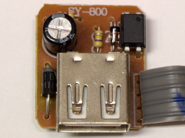
There isn’t a whole lot happening on the output board aside from the fly-back diode dumping the transformer’s energy into the output filter capacitor and a resistor providing bias current to the zener diode driving the optoisolator.
From an electromagnetic interference point of view, having the transformer’s secondary routed across the AC board, through the ribbon cable, before its round trip around the DC board sounds horrible. I doubt this design would pass FCC compliance tests.
MORE: 10 Inexpensive Automotive USB Adapters Tested
MORE: Best Deals
DC Board Bottom
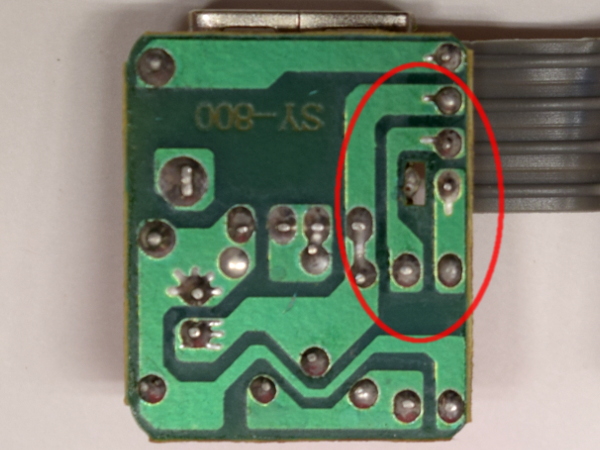
If separation between mains and low voltage on the AC board made you cringe, it gets much worse on the DC board. Less than 0.5mm separate one of the AC-side optoisolator traces from the USB connector shield’s tab, while the innermost vertical trace corresponding to USB negative is a mere 0.6mm away from the isolator’s mains-referenced voltages.
This trace routing likely violates every credible safety standard in existence. Assuming the transformer and EMI capacitor don’t fail first, these traces are where I expect arcs to occur.
MORE: 10 Inexpensive Automotive USB Adapters Tested
MORE: Best Deals
-
sitehostplus This is no joke. I once fried a mp3 player in a usb wall charger before. So I now only use either my computer, or a geniune apple charger.Reply -
laura.morris.ga Thank you for this incredibly valuable information. It's nice to see someone out there looking out for the regular guy who doesn't have this level of knowledge about electronics.Reply -
omegaman2 This manufacturing, and marketing of imitation goods, and in this case electronic products can have very serious consequences, to the point of death, or serious injury. Thank you for your awareness, and knowledge about chargers that are not worth saving a couple of dollars.Reply -
Lutfij In my case, I'd wait to see what folks had to say about it so they would be my guinea pigs, of sorts. In most cases, I stay away from off quality hardware.Reply
Thank you for the write up though!
;) -
canadianvice One of my critical rules for buying china: nothing connected to direct wall power.Reply
I do have one speaker lightbulb, but that's not powered when I'm not present, and it seems to have come from one of the better plants. Obviously, it's also less of a problem since I don't go out of my way to touch it on a regular basis. -
Kennyy Evony how about, listing an alternative without all the flaws? Complaining does not fix anything. List an adapter without all the flaws that costs exactly the same for people to buy? Wouldn't that be a better article? Same price, a lot less risks for consumers? win?Reply -
TMTOWTSAC Reply20566315 said:how about, listing an alternative without all the flaws? Complaining does not fix anything. List an adapter without all the flaws that costs exactly the same for people to buy? Wouldn't that be a better article? Same price, a lot less risks for consumers? win?
The title and description seem to imply that this is the first of several reviews to come. Since this first product presents an outright safety risk, I take zero issue with presenting it now rather than collating all results first. As far as producing a better article, you are presuming an alternative meeting your criteria does actually exists. While I have no doubt quality 5W adapters can be found cheaper than Apple's ($19 list price at Apple) I would be shocked if any of them could be found for $1.50. -
razor512 Reply20564820 said:This is no joke. I once fried a mp3 player in a usb wall charger before. So I now only use either my computer, or a geniune apple charger.
I fried mine also, but with a quality charger, Some MP# players do not play nicely with quickcharge 2.0 and 3.0 chargers.
Here are the photos of mine after it failed.
Funny thing was that the battery was perfectly fine, the protection circuit kicked in and cut the output and input to the battery for a few minutes, then it self-reset and the battery continued to work fine (it now runs a flashlight).
https://imgur.com/a/aOLQr
Beyond that, I have an old DIY USB charger that works really well, and has the lowest noise of any of the OEM chargers that I have used so far.
It is basically a USB port wired to the 5V rail of a 550 watt power supply. Even when charging my android tablet at 2 amps, the voltage is completely stable at 5V, and those cheap 5V amplifier circuits can run from it without filtering while on standard chargers that come with smartphones, will have lots of noise.
-
alextheblue Reply
Half my family uses Apple hardware and OE Apple accessories. The failure rate on the smaller Apple charging blocks is higher than I would have expected, given the cost. Since they have been conditioned to only use Apple accessories, I bought a couple of them the much larger Apple charging blocks you see used for iPads, to replace failed compact Apple blocks. Meanwhile I primarily use high-end third party chargers.20564820 said:This is no joke. I once fried a mp3 player in a usb wall charger before. So I now only use either my computer, or a geniune apple charger.
That depends on the charger. Just because it supports QC doesn't mean it is guaranteed to have issues like that. I've got a 2-port 39W (combined) Anker charger that supports QC 3.0 but it also supports what Anker calls PowerIQ. Works great with anything I've thrown at it, and I also use it with a 10W Qi mat.20566658 said:I fried mine also, but with a quality charger, Some MP# players do not play nicely with quickcharge 2.0 and 3.0 chargers. -
Daniel Sauvageau Reply
As the intro says, this adapter (hopefully) sets the low bar. I'm not "complaining" about the low quality, I am exposing it to drive awareness of how dangerous or even potentially lethal these cheap generics can potentially be. Increasing awareness reduces the number of people who will let themselves be tempted by suspiciously inexpensive adapters of questionable origins. Fewer people buying dangerous adapters will hopefully reduce demand and sufficiently reduced demand could potentially reduce offer. No awareness would allow propagation of these death traps to go completely unchecked.20566315 said:how about, listing an alternative without all the flaws? Complaining does not fix anything. List an adapter without all the flaws that costs exactly the same for people to buy?
As for suggesting better quality alternatives, as TMT already wrote, I seriously doubt there are any decent quality adapters around the $2 mark or at the very least, the chances of stumbling upon one are slim. There was an intro story to this series that was supposed to come out first but some publishing pipeline hiccups delayed it. I have about a dozen sub-$5 adapters in my presumed horror box and I'm not expecting them to achieve a passing grade. I also have a few $10 adapters which I'm hoping will at least get most of the way to a passing grade. I'll get to them in due time.
Right now, I'm half-way done testing a fairly promising aftermarket one (almost perfectly flat 5.06V from 0A through 8.6A regardless of test conditions with less than 20mV or RMS noise) but it is ~$25, so I'd be disappointed to get anything less. The next one after that will be a ~$10 adapter from a rising one-stop-for-everything home brand that I haven't taken out of its original box yet.
I'll probably rotate sub-$5, ~$10 and $20-and-up adapters until I exhaust my inventory for a given tier as exhausting my "horror-class" adapters first might get depressing. It also increases the chances that I may have something worth recommending once in a while, albeit at a higher cost.
