Apple 5W Adapter Knock-offs: The Colorful A1265 Tear-Down
Isolation In A Safe Power Adapter
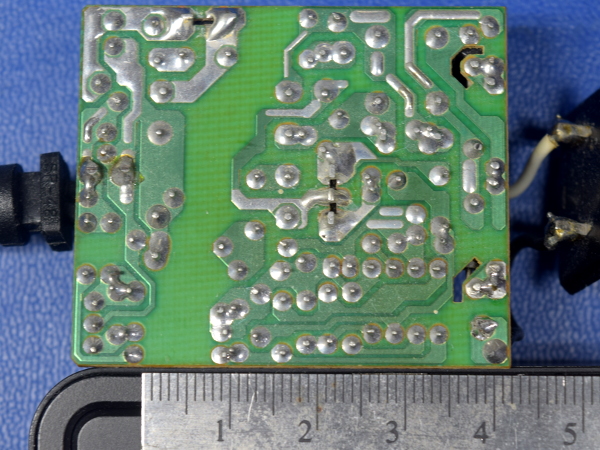
For comparison’s sake, here’s the back of my old DI-524’s dead power adapter. As you can see, it has a minimum separation of five millimeters between primary and output. This is typical of genuine UL-listed power adapters and 10 times what we found on the bogus A1265. Also, in AC input areas where an arc could cause a short directly across the input, anti-tracking slots are present to increase the creepage distance and prevent a fault from burning itself a path across the board, potentially bypassing the fuse. All of these simple precautions greatly reduce the risk of electrical shock and fire.
In a compact adapter like the A1265 shell, anti-tracking slots as narrow as 0.25mm would be enough to at least meet VDE 0110-1 requirements for up to 1.2kV pulse voltage across safety isolation boundaries.
MORE: 10 Inexpensive Automotive USB Adapters Tested
MORE: Best Deals
DC Board Schematic
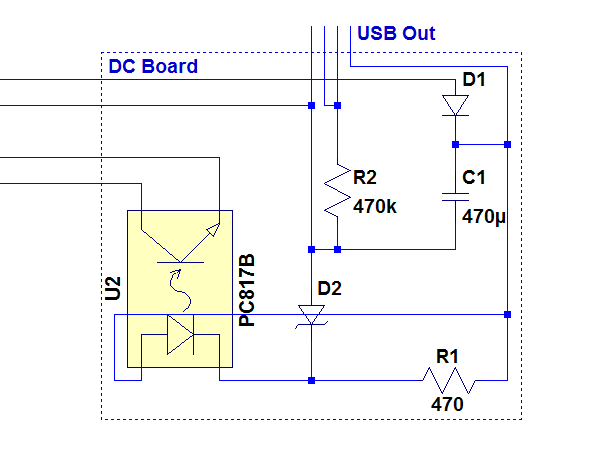
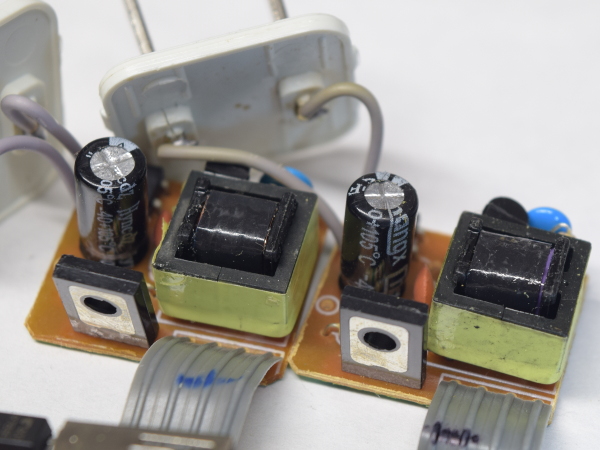
The output board’s schematic is quite simple: D1 is either a fast recovery or Schottky diode in charge of rectifying current pulses from the flyback transformer (for storage in the electrolytic capacitor at C1). R1 provides sufficient bias current to produce the zener voltage across the zener diode D2, which is the nominal output voltage minus the opto-isolator LED’s forward voltage at whatever current it needs to turn the oscillator off.
When the output voltage is low, voltage across the opto-isolator’s LED is too low to turn it on and the oscillator operates at its maximum capacity. Once the output voltage rises ~1.1V above the zener diode’s, current flows through the LED, causing the photo-transistor to rob current from the oscillator’s base drive. Then, the oscillator’s output gets reduced or turned off. This is elegant in its simplicity, but not particularly precise.
MORE: 10 Inexpensive Automotive USB Adapters Tested
Get Tom's Hardware's best news and in-depth reviews, straight to your inbox.
MORE: Best Deals
Failing The Y-Class
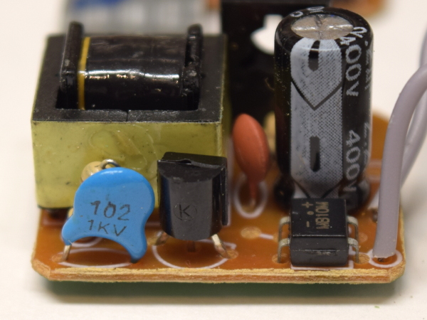
Switching power supplies generate considerable noise, some of which makes its way to the output via capacitive coupling between windings within the transformer. To mitigate that noise, a return path across the isolation boundary must be provided. Since the capacitor used for that purpose is safety-critical, explicitly safety-rated Y-class capacitors are mandatory. Y1-class capacitors must be able to withstand peak voltages up to 8kV, while the more common Y2-class only needs to withstand 5kV. Here, though, we get a generic blue ceramic capacitor with no safety marks rated for just 1kV.
If arcs don’t jump gaps on the DC board first, this capacitor is my second pick as most likely failure point.
MORE: 10 Inexpensive Automotive USB Adapters Tested
MORE: Best Deals
Y Size Matters
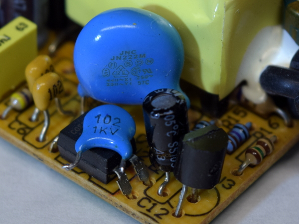
How else can you tell the difference between a genuine Y-class capacitor and a regular ceramic one? Size is a pretty good indication: Y-class capacitors achieve their safety via a combination of thicker dielectric layers between capacitor plates, more dielectric overlap around its plates’ perimeter to prevent flash-over, using dielectrics optimized for high breakdown voltage instead of high dielectric constant, and stacking capacitors in series to prevent the electric field from concentrating around a single fault, all of which yield much lower values for a given volume.
Here, my dead adapter’s 2.2nF Y1-class capacitor is roughly 20 times the bulk of the generic adapter’s nameless 1nF 1kV ceramic capacitor, or around 10 times as large, nanofarad for nanofarad.
MORE: 10 Inexpensive Automotive USB Adapters Tested
MORE: Best Deals
Input And Output Capacitors
Of my four adapters, three use Hyncdz-branded electrolytic capacitors for both the input and output, while the fourth uses Chengx ones instead. How good are they? My rule of thumb is that if searches for a brand fail to pull the manufacturer in one page of results, assume they are somewhere between passable and no good at all. Both of these brands have little online presence beyond Chinese parts distributors and forum posts about bad caps.
On that note, I recently heard a whistle-spittle (capacitor venting) noise to the right of my computer desk, but couldn’t pinpoint its origin before it ended. All of my equipment still appears to be working normally, which means I’ll have to go on a failed capacitor hunt to find it.
MORE: 10 Inexpensive Automotive USB Adapters Tested
MORE: Best Deals
Standby Power
Now that the initial tear-down part is over, it is time to evaluate performance, starting with how much power this adapter draws while doing nothing.
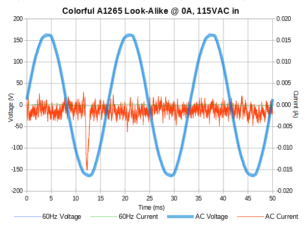
In an unloaded condition, the oscillator plays dead most of the time. The current waveform only shows an occasional peak when the oscillator fires to top off the output capacitor, drawing 14mW at 115V and 16mW at 230V. Both results handily beat level-VI’s 100mW ceiling for single-rail sub-6V power adapters in the 1-49W range, so we have nothing to complain about.
Now let’s see how well efficiency holds up under load.
MORE: 10 Inexpensive Automotive USB Adapters Tested
MORE: Best Deals
Power Efficiency
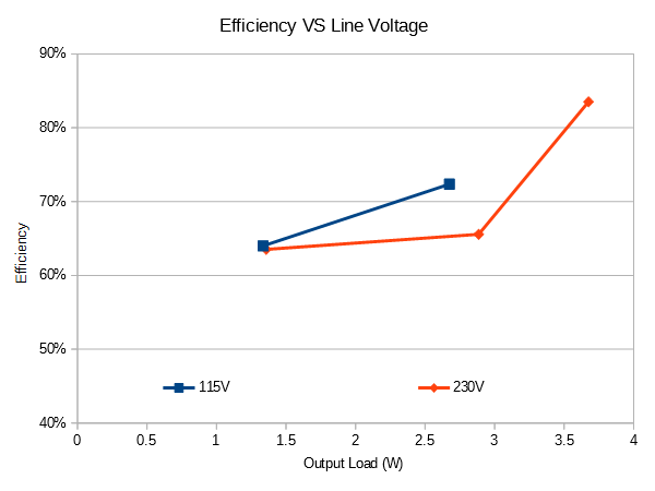
At 115V, this adapter’s efficiency stands at 64% under a 250mA load. It improves to 72% at 500mA, which is barely sustainable. Warmed up, crossing that 500mA threshold sees the output voltage collapse to 4V. Under 230V line input, efficiency at 250mA is slightly worse (63%), improving to 66% at 500mA and peaking at 84% under a 750mA load. There, the oscillator eventually shuts down after warming up for several minutes. All of these efficiency measurements are fair enough for level-V, which only requires 58% from 5W adapters, but they fall short of meeting VI’s 77% minimum.
Had these adapters delivered their claimed 1A output current, efficiency may have landed between decent and surprisingly good.
MORE: 10 Inexpensive Automotive USB Adapters Tested
MORE: Best Deals
Output Quality
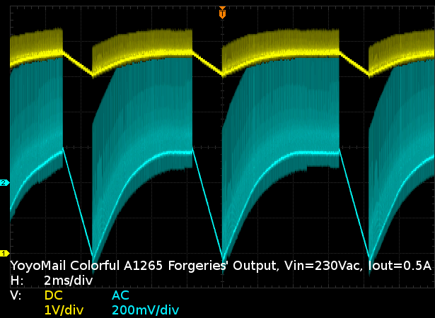
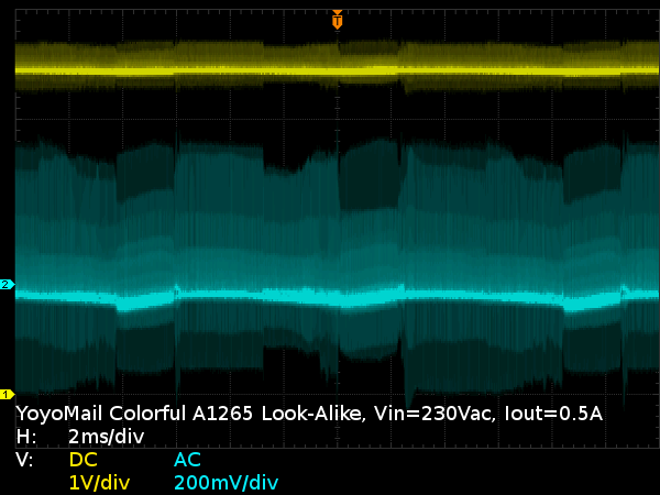
All of the efficiency in the world is meaningless if output quality isn’t there to match it. Here, we see about 600mVPP worth of ringing, likely caused by the output filter capacitor’s high parasitic impedance (ESL+ESR) superposed to an additional 600mVPP of ripple from the oscillator cycling on and off to maintain the output voltage within reasonable bounds.
This pattern repeats at all load levels, making these adapters particularly ill-suited for any device sensitive to power supply noise and ripples.
MORE: 10 Inexpensive Automotive USB Adapters Tested
MORE: Best Deals
Output Quality, Part II
Sometimes the adapter ends up operating in a continuous fashion, rather than as an on-off regulator. When it does, this eliminates most of the 600mV on/off ripple, but still puts out roughly 1VPP worth of switching noise.
MORE: 10 Inexpensive Automotive USB Adapters Tested
MORE: Best Deals
Output Regulation
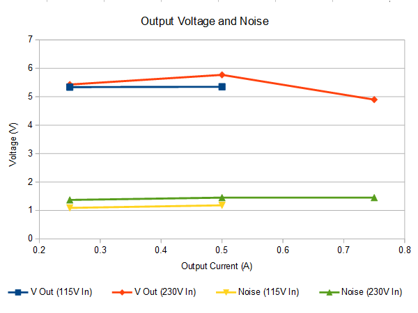
At 115V input, the output is a steady 5.4V until 600mA while cold versus 500mA after warming up, dropping sharply beyond that. At 230V, the output also starts around 5.4V, peaks near 5.8V at 500mA, and tails off below 5.4V shortly past 750mA when cold (5V after warm-up). On the ripple and noise side of things, the adapter is consistently 200mVPP noisier at 230V.
If you are concerned with the accuracy, repeatability, and cleanliness of your power adapter's performance, this one clearly isn't for you.
MORE: 10 Inexpensive Automotive USB Adapters Tested
MORE: Best Deals
-
sitehostplus This is no joke. I once fried a mp3 player in a usb wall charger before. So I now only use either my computer, or a geniune apple charger.Reply -
laura.morris.ga Thank you for this incredibly valuable information. It's nice to see someone out there looking out for the regular guy who doesn't have this level of knowledge about electronics.Reply -
omegaman2 This manufacturing, and marketing of imitation goods, and in this case electronic products can have very serious consequences, to the point of death, or serious injury. Thank you for your awareness, and knowledge about chargers that are not worth saving a couple of dollars.Reply -
Lutfij In my case, I'd wait to see what folks had to say about it so they would be my guinea pigs, of sorts. In most cases, I stay away from off quality hardware.Reply
Thank you for the write up though!
;) -
canadianvice One of my critical rules for buying china: nothing connected to direct wall power.Reply
I do have one speaker lightbulb, but that's not powered when I'm not present, and it seems to have come from one of the better plants. Obviously, it's also less of a problem since I don't go out of my way to touch it on a regular basis. -
Kennyy Evony how about, listing an alternative without all the flaws? Complaining does not fix anything. List an adapter without all the flaws that costs exactly the same for people to buy? Wouldn't that be a better article? Same price, a lot less risks for consumers? win?Reply -
TMTOWTSAC Reply20566315 said:how about, listing an alternative without all the flaws? Complaining does not fix anything. List an adapter without all the flaws that costs exactly the same for people to buy? Wouldn't that be a better article? Same price, a lot less risks for consumers? win?
The title and description seem to imply that this is the first of several reviews to come. Since this first product presents an outright safety risk, I take zero issue with presenting it now rather than collating all results first. As far as producing a better article, you are presuming an alternative meeting your criteria does actually exists. While I have no doubt quality 5W adapters can be found cheaper than Apple's ($19 list price at Apple) I would be shocked if any of them could be found for $1.50. -
razor512 Reply20564820 said:This is no joke. I once fried a mp3 player in a usb wall charger before. So I now only use either my computer, or a geniune apple charger.
I fried mine also, but with a quality charger, Some MP# players do not play nicely with quickcharge 2.0 and 3.0 chargers.
Here are the photos of mine after it failed.
Funny thing was that the battery was perfectly fine, the protection circuit kicked in and cut the output and input to the battery for a few minutes, then it self-reset and the battery continued to work fine (it now runs a flashlight).
https://imgur.com/a/aOLQr
Beyond that, I have an old DIY USB charger that works really well, and has the lowest noise of any of the OEM chargers that I have used so far.
It is basically a USB port wired to the 5V rail of a 550 watt power supply. Even when charging my android tablet at 2 amps, the voltage is completely stable at 5V, and those cheap 5V amplifier circuits can run from it without filtering while on standard chargers that come with smartphones, will have lots of noise.
-
alextheblue Reply
Half my family uses Apple hardware and OE Apple accessories. The failure rate on the smaller Apple charging blocks is higher than I would have expected, given the cost. Since they have been conditioned to only use Apple accessories, I bought a couple of them the much larger Apple charging blocks you see used for iPads, to replace failed compact Apple blocks. Meanwhile I primarily use high-end third party chargers.20564820 said:This is no joke. I once fried a mp3 player in a usb wall charger before. So I now only use either my computer, or a geniune apple charger.
That depends on the charger. Just because it supports QC doesn't mean it is guaranteed to have issues like that. I've got a 2-port 39W (combined) Anker charger that supports QC 3.0 but it also supports what Anker calls PowerIQ. Works great with anything I've thrown at it, and I also use it with a 10W Qi mat.20566658 said:I fried mine also, but with a quality charger, Some MP# players do not play nicely with quickcharge 2.0 and 3.0 chargers. -
Daniel Sauvageau Reply
As the intro says, this adapter (hopefully) sets the low bar. I'm not "complaining" about the low quality, I am exposing it to drive awareness of how dangerous or even potentially lethal these cheap generics can potentially be. Increasing awareness reduces the number of people who will let themselves be tempted by suspiciously inexpensive adapters of questionable origins. Fewer people buying dangerous adapters will hopefully reduce demand and sufficiently reduced demand could potentially reduce offer. No awareness would allow propagation of these death traps to go completely unchecked.20566315 said:how about, listing an alternative without all the flaws? Complaining does not fix anything. List an adapter without all the flaws that costs exactly the same for people to buy?
As for suggesting better quality alternatives, as TMT already wrote, I seriously doubt there are any decent quality adapters around the $2 mark or at the very least, the chances of stumbling upon one are slim. There was an intro story to this series that was supposed to come out first but some publishing pipeline hiccups delayed it. I have about a dozen sub-$5 adapters in my presumed horror box and I'm not expecting them to achieve a passing grade. I also have a few $10 adapters which I'm hoping will at least get most of the way to a passing grade. I'll get to them in due time.
Right now, I'm half-way done testing a fairly promising aftermarket one (almost perfectly flat 5.06V from 0A through 8.6A regardless of test conditions with less than 20mV or RMS noise) but it is ~$25, so I'd be disappointed to get anything less. The next one after that will be a ~$10 adapter from a rising one-stop-for-everything home brand that I haven't taken out of its original box yet.
I'll probably rotate sub-$5, ~$10 and $20-and-up adapters until I exhaust my inventory for a given tier as exhausting my "horror-class" adapters first might get depressing. It also increases the chances that I may have something worth recommending once in a while, albeit at a higher cost.
