10 Inexpensive Automotive USB Adapters Tested -- Are They Any Good?
First Order Of Business
Before putting these adapters to the test, it would be helpful to know what they need to be tested for, starting with what the power from a running vehicle’s 12 V outlet looks like.
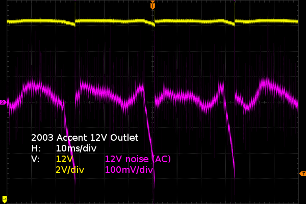
Here are waveforms from my 2003 Hyundai Accent, a car that I rescued from the scrapyard a few years ago and should be reasonably representative of the average rust bucket. As far as I know, all major electrical parts are factory originals apart from the battery, which I put in less than three years ago. The yellow trace shows the DC voltage sitting at about 14.4 V, slightly on the high side for lead-acid battery charging voltage. The pink trace shows the AC noise, which is the most interesting line since these little adapters have to be able to reject as much noise as possible.
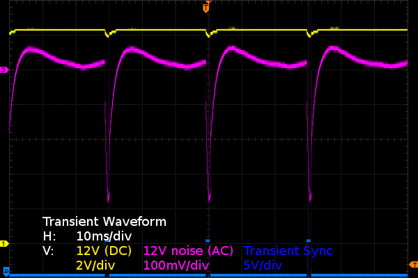
I had never scoped a vehicle’s electrical system before, and I must say I was expecting it to look worse, especially considering the number of signs telling me that this car was abused by at least one of its previous owners. There appears to be only two significant components to the noise waveform: a slight sinusoidal ripple from the alternator’s output and much steeper 300 mV periodic dips from the ignition coils’ current ramps. Some high-frequency noise, which I am guessing comes from the alternator’s field current switching regulator, is also visible. But 50 mVPP of noise in an automotive system is not something worth worrying about. Since the ignition dips are an order of magnitude larger than anything else that I see, I will only attempt to replicate those for my supply noise rejection and input regulation testing. Knowing that my engine has four cylinders and that it takes two ignitions to complete one revolution, you can deduce that it was idling at about 960 RPM when these waveforms were captured.
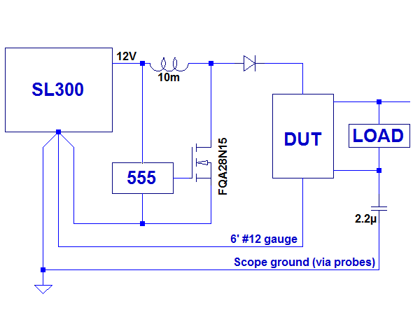
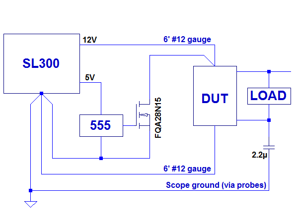
How will I be simulating those periodic transients? At first, I considered using a switched inductor and a snubber circuit to replicate the ignition coils’ sawtooth ramp. But when I got to the point of testing the 555 and FET (FQA28N15) with a resistor before risking destroying them with an inductor, I realized that the 555’s output from a 5V supply was too low to drive the FET fully on, and that it was drawing just enough current as-is to produce 400 mV dips on its own. So, I decided to go with a simplified circuit along the lines of my diagram. I also shortened the pulse width to roughly one millisecond so I could capture more detail around the rising and falling transient edges. The plateaus between edges are of little importance as long they are wide enough to show what voltage the regulator settles at between transitions or the lack of timely settling should that case arise.
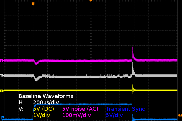
I am relying on the positive wire’s resistance to provide the voltage drop, and using a separate return wire for the FET to keep transient current away from the device under test (DUT) ground. Having the DUT’s ground bounce by 400 mV as the positive side dips by 400 mV would directly translate to all waveforms showing that same 400 mV bounce on the oscilloscope, making analysis far more difficult than it should be. With separate ground wires, the DUT’s ground only carries the DUT’s much smaller and nearly constant current for a given load, rendering it negligible for transient response and noise measurements purposes. The 2.2 µF capacitor between DUT load ground and oscilloscope ground reduces the amount of extraneous noise the oscilloscope probes pick up from the ground wiring’s parasitic inductance. Due to the high current draw from my transient generator, I could not completely eliminate the common-mode noise it causes from my measurements, and the baseline waveforms show the amount of noise that needs to be subtracted from results to get the adapters’ actual input transient response. If the adapter’s waveform looks almost exactly like these waveforms, then the transients are part of the measurement setup’s baseline, not the adapter’s response. This is one of those instances where suitable differential probes would have come in handy to eliminate common-mode concerns from the equation.
While the above covers the basic stuff you can expect to see under normal running conditions, there are many abnormal or temporary conditions that automotive circuits are expected to tolerate, the most common being load dumps. What is a load dump? That’s when heavy electrical loads or short-circuits cause the vehicle’s electrical system voltage to dip, which the voltage regulator responds to by cranking the alternator’s field winding current up to raise system voltage back within the normal range. Then the load suddenly drops, causing the alternator’s output voltage to shoot up until the regulator reels in the field current, which may take a few milliseconds. What sort of everyday use can trigger such a load dump? Boosting a vehicle with a dead battery. When you connect your running car to another with a dead battery, the field current gets maxed out to charge the dead battery. Your alternator also sees massive load swings as the other vehicle’s engine cranks over and (hopefully) starts, or when you disconnect the jumpers after giving up. A healthy battery with good wiring to the alternator, a properly working voltage regulator, and decently clean contacts throughout will absorb the bulk of the excess energy much like a surge suppressor and prevent the system voltage from surging up by more than a few volts. On the other hand, a weak battery, defective regulator, and corroded electrical connections can cause voltage to shoot up well beyond 40 V for short durations. If you do some of your own car maintenance, add your engine block’s ground straps, battery cables, and their connecting bolts to your periodic inspection list if they aren’t already on it. I have watched many car repair videos over the past year, and broken ground straps appear to be a common cause of major electrical issues ranging from no-start to blown engine management computers, despite those systems being ruggedized against nearly every failure mode within reason. To be safe, automotive USB adapters should contain some degree of protection against this as well. You wouldn’t want to ruin your $500 phone or tablet due to a corroded, loose, or broken $3 strap somewhere under the hood.
If I wanted to test these adapters for some degree of tolerance to automotive surges, I would reconfigure my circuit to insert a large inductor between the power supply and DUT, reconfigure the 555 as a one-shot timer, tweak the pulse width to get a significant surge current (say 10 A) and let it loose. To avoid destroying my FET, I would also need to put together some sort of snubber to keep those spikes below 150 V should the DUT fail open.
Get Tom's Hardware's best news and in-depth reviews, straight to your inbox.
Due to the inherently destructive nature of this test and the low likelihood that any of these units will survive it without permanent damage, I am going to skip it and simply call fail the adapters with no apparent input protection.
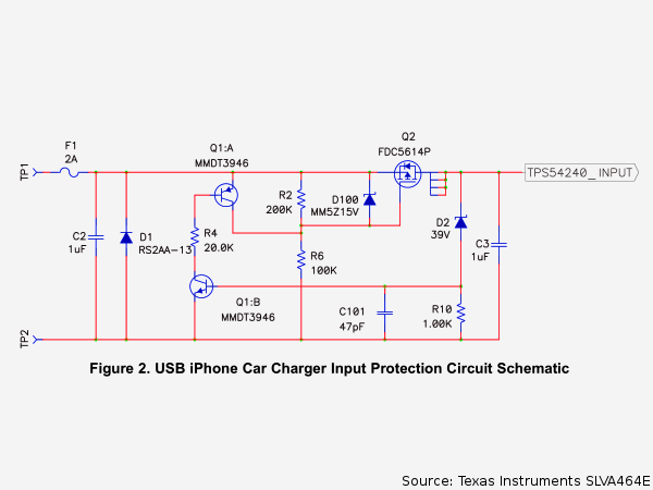
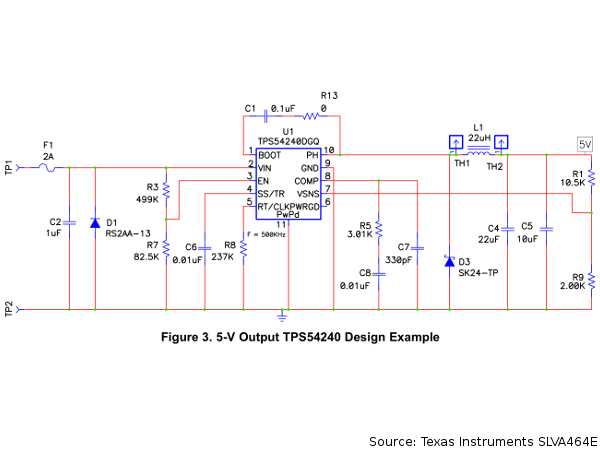
What would such a protection circuit look like? Here’s an application report from Texas Instrument going through the design process of such a power adapter. The input protection section uses a diode and fuse for reverse polarity protection, and a simple P-channel FET configured as a linear regulator to keep the output presented to the switching regulator under 40 V. Between the 60 V P-MOS and its ~40 V output voltage to the switching regulator, TI’s design should cope with transients up to about 100 V, hopefully high enough to devices safe in vehicles with reasonably healthy batteries and electrical systems in decent condition.
Why is protection against transients such a big deal? Because I expect all of the units in this little round-up to be little more than switching buck regulators similar to TI’s example. In a buck regulator, the only thing standing in the way of input voltage (including any transients) appearing at the output is the series switching transistor inside the monolithic switching regulator integrated circuit. Should the switching element ever fail shorted from drain to source or collector to emitter (input to output), whatever comes in will go straight out. Very few USB-powered devices will react favorably to receiving 12 V or more. The same applies to high-efficiency PC supplies that use buck DC-DC converters for their minor rails. Now that USB has power delivery profiles going up to 20 V, I would hope that manufacturers designing USB 3.x devices and devices with Type-C ports will build their power input/output circuitry to be 20 V-safe and protect against ports providing the wrong voltage for whatever reasons.
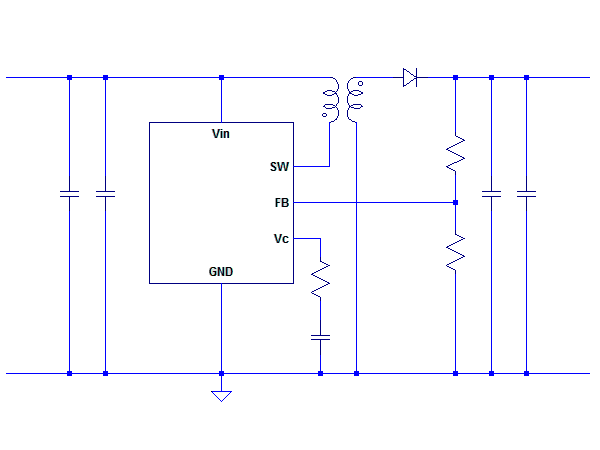
If I designed my own 12 V to USB adapter, I’d go down the non-isolated flyback or forward converter route, where even a catastrophic fault or failure on the input side would have little chance of affecting loads beyond a loss of power for little extra cost. The cheap converters already have a ferrite core for their inductors; converting those into transformers only requires an extra winding. Should the switch ever fail shorted, the transformer core would saturate and become unable to transfer any further energy until given a chance to reset, the primary winding would behave like a dead short, and the chip package’s bonding wires would blow up. The end. Why not full isolation? Because it adds a handful of extra components and does not add much protection at 12-24 V unless your vehicle is wired chassis-positive (a common practice over 20 years ago to reduce rusting), in which case you may want full isolation to eliminate the risk of shorting your metal phone or tablet’s chassis-negative to your vehicle’s chassis-positive. If you are still using wired analog audio from your phone or tablet to your amplifier, then a fully isolated adapter may also reduce ground loop noise if you happen to have a noticeable amount of it.
Should I expect to see any such protection in the units I am about to take apart? I don’t think so. Only one of them appears to even have a fuse, the most basic of protections. I’d be surprised if any of the others had anything fancier.
Getting To Testing
What better guinea pigs to try my experimental test rig on than the cheapest adapters, which I have the lowest expectations for? That turned out to be a good idea since my 12 V socket was initially wired backwards and I ended up frying the orange adapter. I went back to the store and bought the internally identical purple one as a replacement.
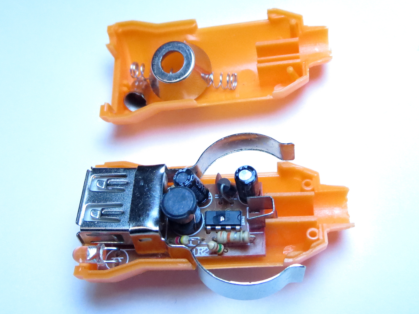
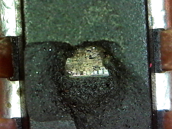
Moments after I turned on my power supply, I heard a sharp crack coming from the adapter, followed by the unmistakable electronics smell after the magic smoke lets out. It did not take long into the autopsy to find the exploded remains of the switching regulator. The support component complement is exactly what I was expecting from these things: a few resistors for the feedback voltage divider, what appears to be an RC timing network, and bypass capacitors for the input and output. At first, I thought the adapter may have been defective, but then I remembered disconnecting the socket’s cables to untangle them months ago while clearing my workbench. Sure enough, I had plugged them in backwards before putting the cable away. At the bottom of the crater, you can see pads along the edge of the die. From the look of it, burning bonding wires vaporized the chip’s packaging. Moral of the story? When you rig stuff together from a bunch of partially assembled bits and pieces, remember to check polarity on everything. Especially on parts that haven’t been checked and used in a while.
What is my test plan for these things?
- General visual inspection commentary.
- Apply load up to the maximum rating, 3.7 A (the maximum my dummy load is able to draw from a 5V supply after wiring losses in my 120 cm #24 USB cable) or until the output voltage drops to 4.75 V, whichever is least, and let the adapter warm up for at least three minutes before taking measurements since many adapters’ output capability dropped drastically after warming up during preliminary testing.
- Measure output voltages at 500 mA, 1000 mA, 2100 mA, and 3100 mA, where applicable, or the current where voltage drops below 4.75 V if less than the rated output.
- Output noise at measured output voltages and currents.
- Efficiency at measured output voltages and currents.
- Cold and hot short-circuit current.
- Ten-second continuous short-circuit protection test; see if the adapter’s protection prevents immediate self-destruction.
As a reminder, all units claim to have an input voltage rating of 12 V to 24 V. In automotive terms, this should really translate into devices designed to handle at least 30 V of continuous input voltage since the peak charging voltage of a 24 V lead-acid battery system would be around 29 V.
Current page: Benchmarking
Prev Page The Quest For Ubiquitous USB Power Next Page First Batch: The Bullet Trio-
SpAwNtoHell Tho have the knoledge to test all of that myself i never bothered as my intuition always pointed that generic are beter next to nothing only. Genuine branded is what i always used for the all explained and revealed in your article; like samsung charger, htc charger and so on... and i always used 12 spliters... with the incovenience of the space...Reply -
Math Geek very interesting read. never thought it through this much but always assumed the $1 adapters were junk and generally bought name brand adapters for around $10 or so.Reply
but now i wonder and almost feel like taking one apart just to see what's inside. :) -
Daniel Sauvageau Reply18542197 said:No Anker in the review is a bummer, still, thanks for doing this!
At least one of Anker's Amazon listings has a 3D render showing the internals. At a glance, it seems quite similar to the LDNIO.18542229 said:but now i wonder and almost feel like taking one apart just to see what's inside. :)
If I do another one of these roundups, I'll try to get my hands on one. -
Math Geek i have a couple of the belkin and griffin brands in my cars. they are common adapters found at walmart for $10-15 depending on the model. seems like a decent trade off form the super cheap ones and the super expensive ones.Reply
but now you got the topic started, i wonder if they are worth the price and better than the junk ones i avoided. -
Daniel Sauvageau Well, throw adapter models/brands at me and I'll look around to see which ones I can grab for a reasonable price for Round 2.Reply -
Math Geek my next trip to walmart/target i'll make some notes. they carry roughly the same type stuff as best buy as far as brands go. will look for the midrange models i'd likely buy and post some for you :)Reply -
turkey3_scratch All of these have really high ripple. The ATX spec alone (and I know these don't have to follow that) defines 50mv max for the 5VSB rail. These all chill above 100mv.Reply
