Beamforming: The Best WiFi You’ve Never Seen
Inside On-Chip Phased Arrays
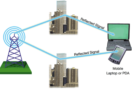
Let’s get a little more specific. You may be familiar with MIMO (multiple-input, multiple-output) technology, first adopted with some 802.11g products and now incorporated into the 802.11n specification. Go back to our pool example. When you drop a stone in the left edge of the pool and the receiver is on the pool’s right edge, some of the waves will travel in a straight path from left to right and arrive at the transmitter via the shortest route possible. However, some waves will bounce off the top, then arrive at the receiver a bit later than the straight-path waves. Some will bounce off the bottom, then up to the top, and then arrive at the receiver. All of these variations emerge from a single stone drop, or radio burst. To a simple receiver, this sounds a bit like confusing, overlapping echoes. This “multipath” effect has traditionally plagued the performance of radio communications.
But what if you used multiple antennas at each end of the pool, applying enough analysis intelligence on each side to turn those echo paths into conduits for different data streams? With multiple antennas on each end, you can send different data streams from different antennas and receive them at the other end in the same manner.
To drag in a different metaphor, think of a highway. If the highway is only one lane, you can have one big truck going full-speed to its destination. However, if you sub-divide that one big lane into three or four narrower lanes, you can have three or four compact cars going to the same destination at the same speed. They just happen to be going there along slightly different paths. When you took good ol’ 54 Mbps 802.11g and its 20 MHz channel highway, divided that highway into multiple sub-channels, and increased the number of antennas, you got 802.11g MIMO.
Specifically, 802.11n typically transmits three data streams and receives two, commonly referred to as a 3x2 antenna array. There are some 3x3 schemes in the works, such as the so-called 450 Mbps WiFi set out by Intel with the launch of Centrino 2, but no access points have arrived yet to support this. Like 802.11g before it, 802.11n can use channel bonding, turning two 20 MHz streams into a 40 MHz pipe. To be totally accurate, you should actually see antenna arrays noted with three numbers: the number of transmit antennas, the number of receive antennas, and the number of spatial streams (or data streams) to use our sub-divided highway analogy. So a 3x3:2 (also noted as 3x3x2) array would have three transmit antennas, three receive antennas, and two spatial streams.
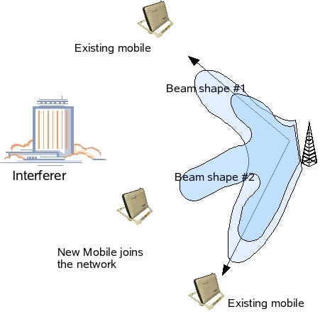
I mentioned earlier that on-chip beamforming was one of the two beamforming methods applicable in WiFi. This works by not only boosting total power gain by having multiple antennas in play, but also phasing the antenna signals so that a higher signal “beam” is cast in the receiver’s direction while less energy can be expended in other directions. With two transmit antennas, you can expend less total energy while quadrupling the transmit signal sent in the beam’s direction. The transmitter/access point only needs to receive a single packet from the client to get a lock on the signal path. Analysis of multiple packets can determine which of the multipath options is optimal at any given time.
The incredible thing is that chip-based beamforming, like MIMO, has been compatible with 802.11a/b/g for years. In fact, the technology is an optional part of the 802.11n standard. Despite its benefits, though, Cisco is the first to deliver on-chip beamforming to market. The enterprise-oriented AIR-LAP1142N access point is Cisco’s first and so far only product to feature beamforming, which it brands as ClientLink. It arrived in the first quarter of 2009, but the firmware that enables beamforming capability didn’t arrive until July. We tested with this firmware literally within days of its release.
Get Tom's Hardware's best news and in-depth reviews, straight to your inbox.
Current page: Inside On-Chip Phased Arrays
Prev Page Beamforming Basics Next Page The Client That Could Be-
pirateboy just what we need, more retarded failnoobs clogging up the airwaves with useless braindead movieclips...yaayReply -
bucifer This article started up pretty good with lots of technical data and the beamforming technology in theory but after that the goodness stopped.Reply
1.You cannot compare two products by testing them with a in-house developed software. It's like testing ATI vs nVIDIA with nvidia made benchmark.
2.If you do something get it done, don't just go with half measures. I don't care if you didn't have time. You should have planned this from the beginning. The tests are incomplete, and the article is filled with crap of Rukus and Cisco. -
Mr_Man In defense of your wife, you didn't HAVE to use that particular channel to view all the "detail".Reply -
@Mr_Man: With a name like yours, I'd think that you'd sympathize with Chris a bit more :P Unless (Mr_Man == I likes men) :DReply
-
Pei-chen Both Tyra and Heidi have personal issues and would be pretty difficult friend/mate.Reply
The network idea sounds better. I couldn’t get my 10 feet g network to transmit a tenth as much as my wired network without it dropping.
-
zak_mckraken There's one question that I think was not covered by the article. Can a beamformaing AP can sustain the above numbers on two different clients? Let's say we take the UDP test at 5 GHz. The result shows 7.3 Mb/s. If we had two clients at opposite sides of the AP doing the same test, would we have 7.3 Mb/s for each test or would the bandwidth be sliced in 2?Reply
The numbers so far are astonishing, but are they realistic in a multi-client environnement? That's something I'd like to know!

