Biostar Hi-Fi B85S3+ Motherboard Review
Why you can trust Tom's Hardware
Layout
You get only the minimal accessories you need: the board, a 5 3/4 x 8 1/4-inch staple-bound manual (it will not lie flat), a driver CD, an I/O shield and a couple of SATA 6Gb/s cables. In truth, I think three cables ought to be standard. In the DIY market, a single optical drive and a system drive are just not enough, especially if that system drive is a small SSD.
Although it doesn't lie flat, the manual is otherwise reasonable. I did not need a magnifying glass to make out the illustrations. The manual offers 10 languages; English, Arabic, French, German, Italian, Japanese, Polish, Portuguese, Russian and Spanish.
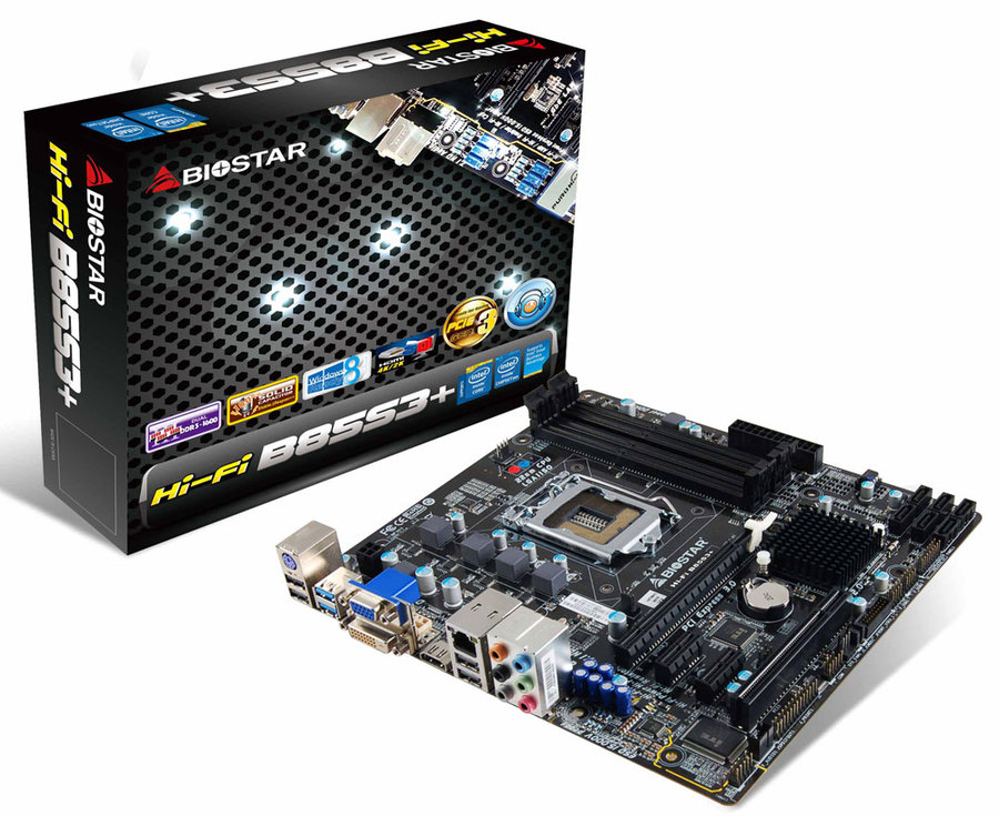
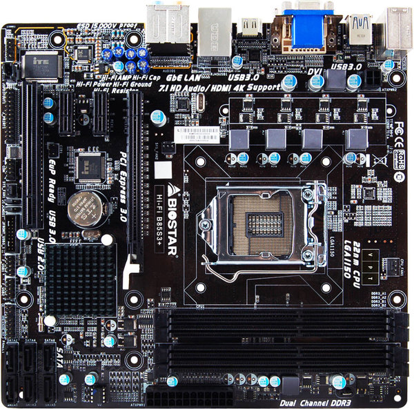
The board's layout is fine. Other than one fan header, all pin headers and other connections are near edges, where most cases will have their cable management openings. As is common on mATX boards, a double-slot video card will block the adjacent expansion slot, in this case the first PCIe x1 slot. Unfortunately, it will also partially obstruct the battery, so plan to remove the video card if you replace the CR2032 lithium-coin cell. The back edge of a long video card will not obstruct the RAM latches, nor is this card near the SATA ports, so they will also remain unobstructed. The SATA ports are clustered in the bottom left corner. Those that operate at 6Gb/s are alternated, so any clips will face out. If you use a SATA 3Gb/s port, though, you'll need to remove its cable to get to the clip on a 6GB/s port's cable behind it. Chassis fan headers are of the 3-pin variety, although the CPU fan header is the usual 4-pin PWM.
The CLRCMOS header comes with a jumper block, and is easy to reach on the left edge. There is another 3-pin header next to it, also with a jumper block on it. This header is not illustrated nor described in the manual (I left it alone). The 4-pin CPU power cable is close enough to the right edge that nothing blocks access to a cable management opening. All capacitors are solid, and the chokes are ferrite core. The front-panel header is in the usual place on the bottom left, and includes pins for a speaker. The audio header is on the very edge at the back left, which is a cleaner placement than the more central position many boards use. There are no indicator LEDS on the board, such as a diagnostic display or a +5VSB pilot. Be sure you've switched your PSU off or unplugged it before adding or removing expansion cards, to be sure the +5VSB is off.
Get Tom's Hardware's best news and in-depth reviews, straight to your inbox.
-
Sakkura Why no info on the fan control for case fans? Do the 3- pin headers allow voltage control, and if so, how does the BIOS handle fan curves?Reply -
SuperVeloce you're joking, right? Practically every motherboard that left the factory in Q1/Q2 2014, has the support for "haswell refresh" cpus.Reply -
Onus Reply
This is a good question. Although there are no case fans on my testbed case, there ought to be a way I can check for this in the future. I'll keep this in mind; thanks.16675885 said:Why no info on the fan control for case fans? Do the 3- pin headers allow voltage control, and if so, how does the BIOS handle fan curves?
-
Calculatron I think this is the motherboard that I said Biostar should have submitted for the sub-$60 LGA-1150 motherboard round-up, back in April.Reply
Better late than never, I suppose! -
Onus Since I was asked to look at the $60-$80 segment, I suspect this board was in that range when THG ordered it; the price may have come down some. It is a nice board, it would not have been unreasonable to make it "Recommended" rather than merely "Approved," although I suspect that one of the ASRock H97 boards may be close enough in price to make that a higher bang/buck proposition.Reply -
quilciri I remember back in 2011, with the Llano chips, if you overclocked them, the USB 3.0 controller would switch to USB 2.0 mode.Reply -
RedJaron Reply
I wouldn't have minded having it come across my bench back then. But I think Joe is right, it was probably just above the price range back then. This would have been tough competition for those other four boards, especially with the four RAM slots. That's something you get with a full-width board. That and a secured board edge ( I really don't like boards that are narrower than the spec and just hang off the edge ). Then again, the H81 chipset can't handle more than two DIMMs, even if you have the space. That's yet another advantage B85 has.16677526 said:I think this is the motherboard that I said Biostar should have submitted for the sub-$60 LGA-1150 motherboard round-up, back in April.
The lack of a TOSLINK doesn't bother me. The board does have the header if you want to buy the break out adapter. But if you don't have Dolby Digital Live or DTS-Connect, you can only get 5.1 audio over the S/PDIF from pre-encoded sources, like a movie DVD. Game sounds and every other generated audio is reduced to 2.0, which you can get from the 3.5mm jack. So unless you're using your computer to watch a lot of movies, and you're using fiber optic cables for audio instead of HDMI, there's not a lot of need for it. -
DonkeyOatie Reply16676133 said:you're joking, right? Practically every motherboard that left the factory in Q1/Q2 2014, has the support for "haswell refresh" cpus.
I wanted a definite statement. There are boards in distant parts of the world that lack this feature.
Firstly, apologies for not making my intention clearer. I knew exactly what I meant but, as a teacher, I should have been less hasty.
I advise a lot of people around the world on system builds as so many of us do. What often comes up for budget systems is the PCPartpicker note. – Some Intel B85 chipset motherboards may need a BIOS update prior to using Haswell Refresh CPUs.
Many of these posters are spending all the money they have on their first build and are full of FUD (Fear, Uncertainty, and Doubt) Often, nothing I can say will persuade them that they do not need a Z97 board like their mate told them to get.
My statement was intended to prompt the reviewer to add wording to the review similar to what SuperVeloce suggested. Say This motherboard supports haswell refresh cpus.
We regulars use this site a lot and 'know' all this stuff, but it is also important to remember the first-timers. -
beetlejuicegr He is right, DonkeyOatie i mean, i also built a system for a friend and i was stressed up until the system booted if i would have to run around to use another cpu to bios update so that the haswell refresh cpu i had would work.Reply

