Sponsored by QUE Publishing
Hard Drives 101: Magnetic Storage
Head Sliders
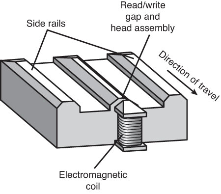
The term slider describes the body of material that supports the actual drive head. The slider is what actually floats or slides over the surface of the disk, carrying the head at the correct distance from the medium for reading and writing. Older sliders resemble a trimaran, with two outboard pods that float along the surface of the disk media and a central “hull” portion that actually carries the head and read/write gap. The figure below shows a typical mini slider. Note that the actual head, with the read/write gap, is on the trailing end of the slider.
The trend toward smaller and smaller form factor drives has forced sliders to become smaller as well. The typical Mini-Winchester slider design was about 4 mm x 3.2 mm x 0.86 mm in size. Most head manufacturers have since shifted to smaller Micro, Nano, Pico, or Femto sliders. The Femto sliders in use today are extremely small—about the size of the ball in the tip of a ballpoint pen. Pico and Femto sliders are assembled by using flex interconnect cable (FIC) and chip on ceramic (COC) technologies that enable the process to be completely automated.
The table below shows the characteristics of the various types of sliders used in hard disk drives.
Hard Disk Drive Slider Types | ||||||
|---|---|---|---|---|---|---|
Slider | Year Introduced | Relative Size | Length (mm) | Width (mm) | Height (mm) | Mass Type (mg) |
Mini | 1980 | 100% | 4.00 | 3.20 | 0.86 | 55.0 |
Micro | 1986 | 70% | 2.80 | 2.24 | 0.60 | 16.2 |
Nano (+ Pressure) | 1991 | 62% | 2.50 | 1.70 | 0.43 | 7.8 |
Nano (- Pressure) | 1994 | 50% | 2.00 | 1.60 | 0.43 | 5.9 |
Pico | 1997 | 30% | 1.25 | 1.00 | 0.30 | 1.6 |
Femto | 2003 | 20% | 0.7 | 0.7 | 0.23 | 0.6 |
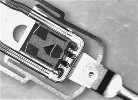
Smaller sliders reduce the mass carried at the end of the head actuator arms, which provides increased acceleration and deceleration, thus leading to faster seek times. The smaller sliders also require less surface area, allowing the head to track closer to the outer and inner diameters, thus increasing the usable area of the disk platters. Further, the smaller slider contact area reduces the slight wear on the platter surface that occurs during normal startup and spindown of the drive platters. The figure below shows a magnified photo of a Femto slider mounted on the head gimbal assembly, which is on the end of the head actuator arm.
The newer slider designs also have specially modified surface patterns that are designed to maintain the same floating height above the disk surface, whether the slider is positioned above the inner or outer cylinders. Conventional sliders would increase or decrease their floating heights considerably according to the velocity of the disk surface traveling beneath them. Above the outer cylinders, the velocity and floating height would be higher. This arrangement is undesirable in newer drives that use zoned bit recording, in which the bit density is the same on all the cylinders. When the bit density is uniform throughout the drive, the head floating height should also be relatively constant for maximum performance. Special textured surface patterns and manufacturing techniques enable the sliders to float at a much more consistent height, making them ideal for zoned bit recording drives.
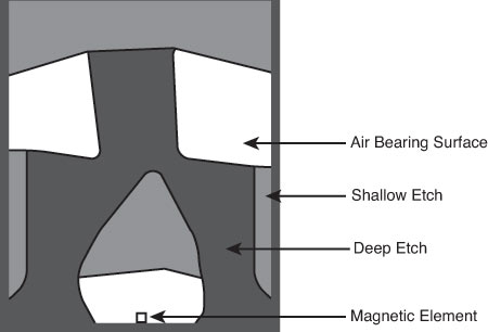
A typical Femto air-bearing slider surface design is shown below.
A Femto slider has three distinct areas with complex shapes designed to achieve a consistent head-to-disk floating height across the disk as well as minimal height loss under high-altitude (low-pressure) conditions. The shallow etch area creates a stepped air inlet allowing airflow to create a positive pressure under the air-bearing surface that lifts the slider away from the disk. The deep etch area creates an opposite negative pressure pocket that simultaneously pulls the slider closer to the disk surface. The combination of positive and negative pressures is designed to balance the force of the suspension arm pushing the slider toward the disk, while keeping the slider at the desired floating height away from the disk surface. The balance of positive and negative pressures stabilizes and reduces the floating height variations commonly found in older slider designs. The first drive using the Femto slider design was the Hitachi 7K60 2 1/2-inch drive released in May 2003. Most of the higher-capacity drives on the market today use this design.
Current page: Head Sliders
Prev Page Read/Write Heads Designs: Magneto-Resistive Heads Next Page Data-Encoding Schemes And Frequency Modulation EncodingGet Tom's Hardware's best news and in-depth reviews, straight to your inbox.
Tom's Hardware is the leading destination for hardcore computer enthusiasts. We cover everything from processors to 3D printers, single-board computers, SSDs and high-end gaming rigs, empowering readers to make the most of the tech they love, keep up on the latest developments and buy the right gear. Our staff has more than 100 years of combined experience covering news, solving tech problems and reviewing components and systems.
-
soccerdocks "Density initially grew at a rate of about 25% per year (doubling every four years)"Reply
If density grows at 25% per year it would actually double in just barely over 3 years. At 4 years it would be 144% greater. -
joytech22 Replywhen passed over magnetic flux transitions.
I somehow expected "Flux capacitors" instead. -
johnners2981 soccerdocks"Density initially grew at a rate of about 25% per year (doubling every four years)"If density grows at 25% per year it would actually double in just barely over 3 years. At 4 years it would be 144% greater.Reply
No you're wrong, how embarrassing :). You're using compound interest. Quit trying to be a smartass -
Device Unknown johnners2981No you're wrong, how embarrassing . You're using compound interest. Quit trying to be a smartassReply
I'm no math guy, in fact i suck at it, but I see his point, why wouldn't it be compound? and even at compound interest is 144 still accurate? please enplane
-
soo-nah-mee I believe soccerdocks is right - example...Reply
Beginning value: 10
After one year: 12.5
After two years: 15.625
After three years: 19.531 (Almost double)
After four years: 24.41 -
johnners2981 Device UnknownI'm no math guy, in fact i suck at it, but I see his point, why wouldn't it be compound? and even at compound interest is 144 still accurate? please enplaneReply
Please enplane??? Compound interest is used to calculate interest and not things like density.
They were right in saying "doubling every four years" and he was trying to correct them when there was no need so showed him who's boss, oh yeah -
johnners2981 soo-nah-meeI believe soccerdocks is right - example...Beginning value: 10After one year: 12.5After two years: 15.625After three years: 19.531 (Almost double)After four years: 24.41Reply
His calculation is right not the application, why is he using compound interest to calculate the percentage increase in density? It doesn't make sense. -
soo-nah-mee johnners2981His calculation is right not the application, why is he using compound interest to calculate the percentage increase in density? It doesn't make sense.It's not compound "interest", but it is compounding. If you say something increases 25% each year, you can't just keep adding 25% of the original value! Silly.Reply
-
striker410 soo-nah-meeIt's not compound "interest", but it is compounding. If you say something increases 25% each year, you can't just keep adding 25% of the original value! Silly.I agree with the others on this one. Since it's adding 25% each year, it is compound. You are thinking of it from the wrong angle.Reply


