Reader's Voice: An Introduction To Home Automation
Wrapping Up The Installation
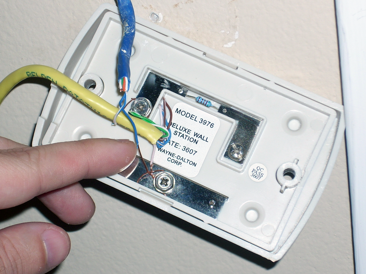
The last toy to set up was the I/O controller used to drive the garage door. I read over the instructions until I was dizzy; per my understanding, the important tidbit was that the relay outputs were marked R1A/R1B for the first output and R2A/R2B for the second. I started with the garage door opener back side.
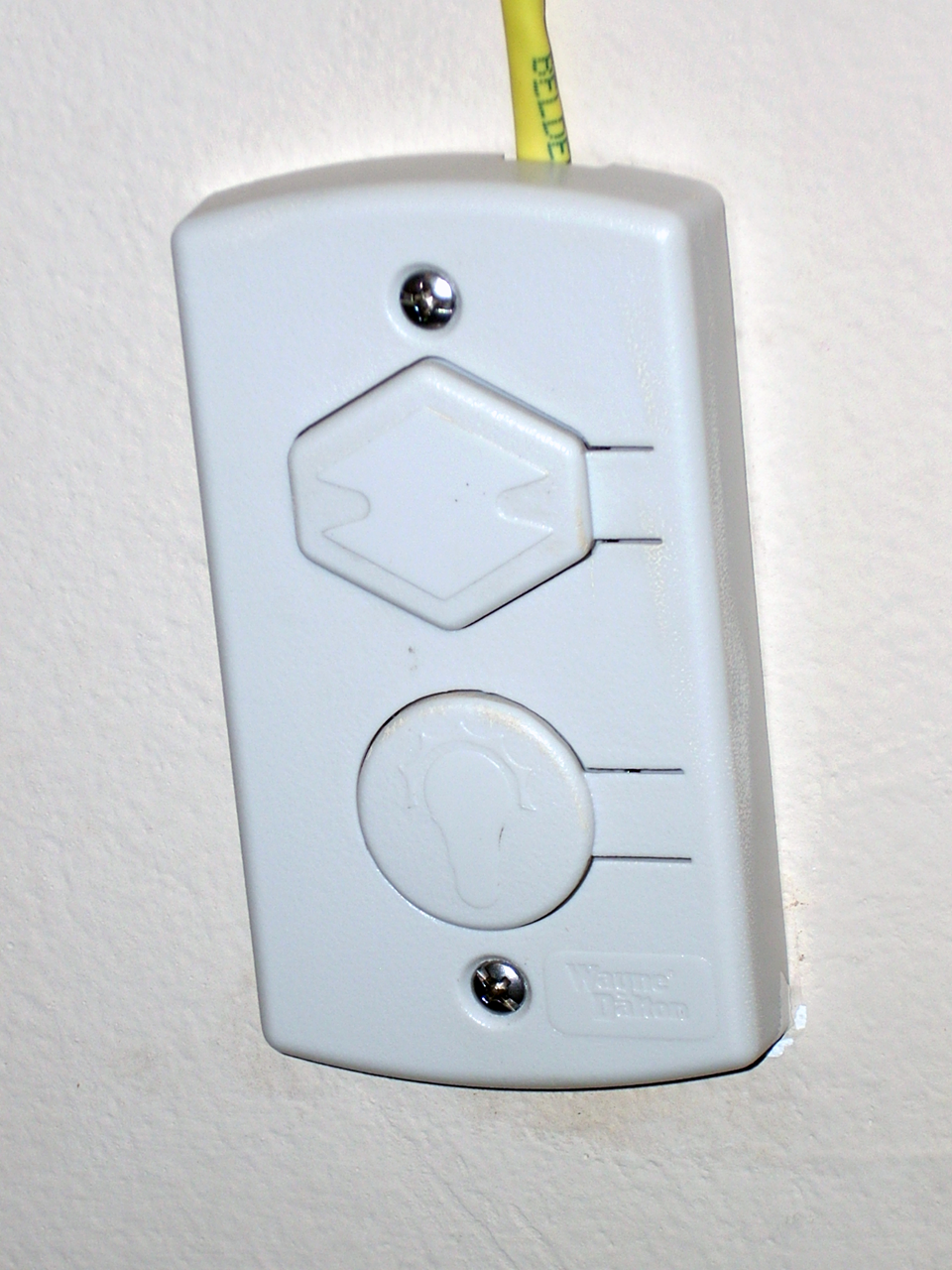
A pair of wires from a CAT5 cable are connected on either electrical side of the garage door button. With the wires connected I put the plate back on the wall.
You can run the cable inside your wall for a cleaner look, but know what you're doing before you try, as its not as easy as it sounds (for most folks). Connecting the other ends of the wires to the relay took a very small screwdriver. Either wire can go to either side, as the relay only closes the circuit. All I had to do was plug the I/O controller into a wall outlet and pair it with a controller per the previous procedure. I did end up having to move an access point to get it paired, but once paired I had no problem with the controller functioning after I moved the access point back into place.
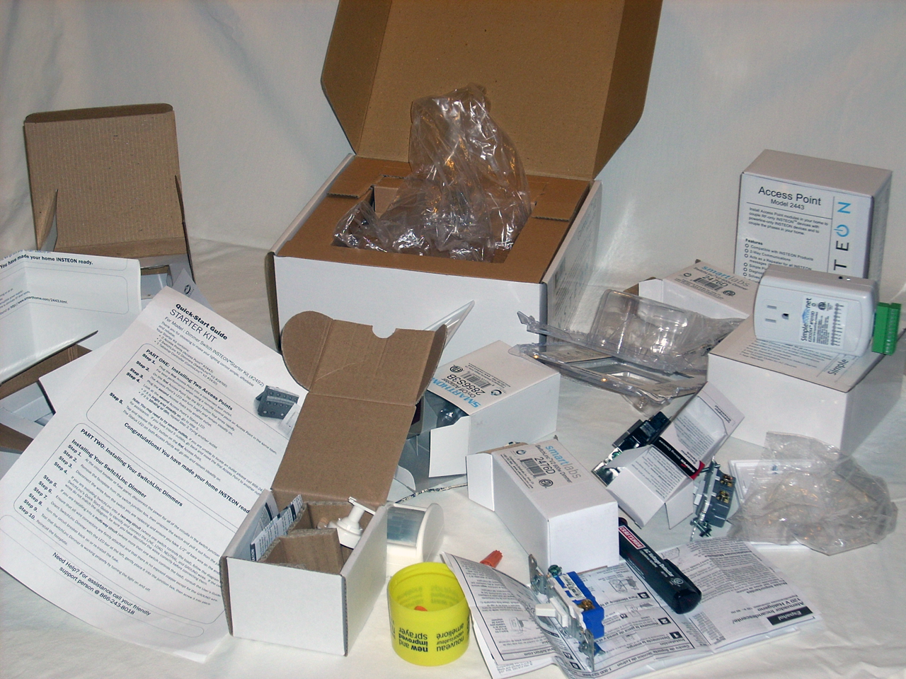
I made a mess out of our kitchen table for a few nights, but my wife forgave me after she got to play with the lights.
Get Tom's Hardware's best news and in-depth reviews, straight to your inbox.
Current page: Wrapping Up The Installation
Prev Page The Browser-Based Software Control Center Next Page Conclusion-
Gin Fushicho Sounds like a lot of fun, though my Grandpa wouldnt like it , he likes to work too much. =/ He might like setting it up though.Reply -
Twoboxer IMO, the problem with "Home Automation" is thatReply
(a) it's fragmented
(b) most applications can be accomplished in most homes with less expensive, individual systems than with any integrated system - even if one existed.
HVAC: Unless you have a large home requiring multiple HVAC zones/thermostats, and unless parts of the home are unoccupied for varying amounts of time, a programmable thermostat is an adequate solution. Setbacks (eg while you are at work) don't seem to save much money with modern HVAC systems in most US climates.
Lighting: If "security" means cycling lights so the house looks occupied, again simple timers are adequate. Unless you have a large, multi-source lighted home, few need automated lighting and "scenes".
Irrigation: If you have any sprinkler system, once again timers and rain sensors do the job well enough.
And so on.
FYI, I have a large primary residence with a networked security system that also controls multiple thermostats. A dedicated PC has replaced a stand-alone DVR to monitor security cameras. A low-voltage, microprocessor controlled system controls lighting.
If these 8-year old systems talked to each other well, maybe I could use the motion detectors to automatically turn lights on and off. And maybe I wouldn't be better off using standard internet cameras to monitor security as I travel between homes.
Its all cool technology, but as a substantial user and tech-lover, I just don't see significant, practical application in most homes. -
Twoboxer Please forgive the double-post, but I couldn't resist pointing out one savings I learned about from all of this.Reply
I use a lot of 130V bulbs in the fixtures controlled by microprocessor controlled lighting system. Most of these bulbs are also oversized for their purpose, and are therefore set to run at, eg, 60% or 75% of maximum voltage when turned on.
I don't know whether I've saved any electricity or not - I doubt it lol - but I have saved a tremendous amount of money on bulbs. EG, there are 11 such bulbs in my kitchen ceiling and they run a minimum of 12 hours per day. I have not replaced a bulb in that set since they were installed over 8 years ago. -
mrubermonkey Buying proprietary systems is bad. Go with equipment that goes by industry standards and the whole issue with home automaton being a long-term investment goes away for the most part. Unless some company's proprietary technology always leads industry standards by leaps and bounds, but this is rare.Reply -
pratik77 If you want the real deal, go for Crestron.Reply
Sure it costs money but so does liquid nitrogen cooled overclocked gaming rigs. -
On the life of light bulbs . . . .Reply
Lamp life is very sensitive to operating voltage - for 120 volts Ge quotes 125 volts as shortening the lamp life to 1/2 and 130 volts to 1/3. The inverse is true - if you put a 130 volt lamp in a 120 volt circuit you can expect over double the lamp life, and if you have a dimmer to soft start then it can last a way lot longer.
http://www.gelighting.com/na/business_lighting/faqs/incandescent.htm -
How can you not mention http://www.CocoonTech.com, the largest DIY home automation site out there.Reply
-
sublifer cocoonerHow can you not mention http://www.CocoonTech.com, the largest DIY home automation site out there.It was mentioned on page 3:Reply
Many of the searches for further guidance landed me at cocoontech.com, and reading other people's guides and questions helped me through the process.


