The Printed Circuit Board Primer
System Specification
A System Specification of the electronic device that is to be made must be formulated. This includes specifying all functions of the system, cost limits, size, operating conditions, etc.
System Block Diagram
A Block Diagram of the system's major functions must be created. How the different blocks are related must also be specified.
Partition The System Into Separate PCBs
Both the reduction in size and the ability upgrade/exchange separate parts of the system are advantages of dividing the system into separate PCBs. The system block diagram gives a good indication of how this should be done. A PC would be divided into main board, graphic card, sound card, floppy drive, power supply, etc.
Determine The Technology To Be Used And The Size Of Each PCBs
When the technology and amount of circuitry on each PCB is determined, the board size must be estimated. If space limitations apply and it turns out that a PCB will be too large, the technology must be changed or the partitioning must be redone. When choosing the technology the quality and speed of the circuit must also be considered.
Get Tom's Hardware's best news and in-depth reviews, straight to your inbox.
Schematic Of The Circuitry On All PCBs
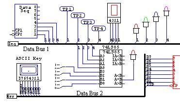
A schematic is a detailed drawing of all connections between the components in a circuit. This must be done for all PCBs in the system, and is nowadays done using Computer Aided Design (CAD). Below is an example of a schematic that was made using CircuitMakerTM
Schematic of the PCB
Simulating The Design
To make sure the designed circuit work properly it must be simulated with a computer program. Such programs take the schematic as input, and can than display the operation of the circuit in numerous ways. This is much more efficient than building a prototype on a breadboard and doing the measurements manually.
Current page: System Specification
Prev Page Surface Mounted Technology Next Page Placing The Components On The PCBs