The Printed Circuit Board Primer
What Is A PCB? Continued
To fasten the components to the PCB their legs are soldered to the conductor pattern. On the most basic PCBs (single-sided boards) the components are located on one side of the board and the conductor pattern on the opposite side. This requires holes in the PCB for the component legs to penetrate the board. Hence, the legs are soldered to the PCB on the opposite side of where the components are mounted. The top and bottom side of a PCB is therefore respectively referred to as the 'Component Side ' and 'Solder Side .'
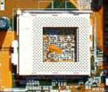
If a component needs to be removable from the PCB after it is manufactured, it is mounted on the board with the use of a Socket. The socket is soldered to the board while the component can be inserted and taken out of the socket without the use of solder. The one shown below is a ZIF (Zero Insertion Force) socket, which allows the component (here a processor) to be inserted easily in place, and be removable. The lever on the side of the socket is used to fasten the component after it is inserted.
ZIF Socket
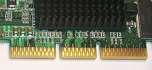
To connect a PCB to another PCB an edge connector is often used. The edge connector consists of small uncovered pads of copper located along one side of the PCB. These copper pads are actually part of the conductor pattern on the PCB. The edge connector on one PCB is inserted into a matching connector (often referred to as a Slot) on the other PCB. In a PC, graphic cards, sound cards and other similar products are connected to the main board with the use of edge connectors.
Edge Connector
(AGP) Slot
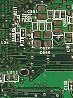
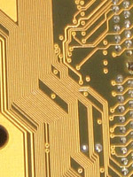
What gives the PCB its green or brown color is the solder mask. This is an insulating and protective coat that protects the thin copper wires and prevents solder from attaching outside the connection points for the components. On top of this colored mask a silk screen is printed. This is text and symbols (often white) printed on the board to label the locations for the different components that are to be mounted. The silk screen is also referred to as the legend .
Get Tom's Hardware's best news and in-depth reviews, straight to your inbox.
Green PCB with white silk screen
Brown PCB without silk screen
Types Of PCBs
Single-Sided Boards
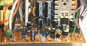
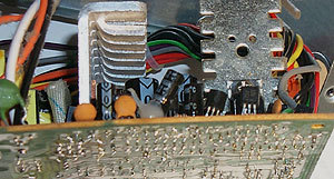
As mentioned earlier the most basic boards have the components mounted on one side of the board and the conductor pattern on the opposite side. Since there only is a conductor pattern on one side, this type of PCB is called 'Single-sided .' This type of board has severe limitations when it comes to routing the wires in the conductor pattern (since there is only one side no wires can cross, and they have to be routed around each other), it is only used in very primitive circuits.
Single-Sided PCB, top view
Single-Sided PCB, bottom view
Double-Sided Boards
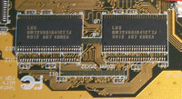
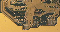
These types of boards have a conductor pattern on both sides of the board. Having two separate conductor patterns requires some kind of electrical connection between them. Such electrical 'bridges' are called 'vias '. A via is simply a hole in the PCB that is filled or plated with metal and touches the conductor pattern on both sides. Since the surface available for the conductor pattern is twice as large compared to a single-side board, and that wires now can cross (by routing them on opposite sides of the board), double sided PCBs are much more suited for complex circuits than the single-sided.
Double-Sided PCB, top view
Double -Sided PCB, bottom view
