Reader How Tos: A System To Convert VHS and 8 mm Tape To DVD
Assembling The System, Continued
12:00 PM - I took a break and joined my wife for lunch.
1:00 PM - I connected the DVD drive to IDE2 connector. I powered the system up OK, and BIOS recognized the drive correctly.
1:20 PM - The Gigabyte motherboard has four IDE connectors, two ATA-33/66/100 connectors and two ATA-133/RAID connectors. The Promise RAID controller 20276 chip drives the latter two connectors, labeled as IDE3 and IDE4. The BIOS allows you to set the Promise RAID controller as an ATA or RAID interface. But I didn't know if the BIOS could be set up to boot from any drive connected to IDE3/4. I set the jumpers on the two Maxtor drives to "cable-select," and used the 80-pin flat-ribbon cable to daisy chain interconnect the two drives to the IDE3 connector. The system powered up fine. BIOS recognized both drives, and I found out that the first drive (at the end of the IDE3 cable) can be set as a boot device. Thank you, Gigabyte! I love it!
1:35 PM - I connected the Fujitsu 20 GB hard drive to the end of the cable plugged into IDE1. The system powered up OK. BIOS recognized the 20 GB drive. I decided to make that my primary boot HD and leave the two Maxtor HDs as my video capture and storage devices.
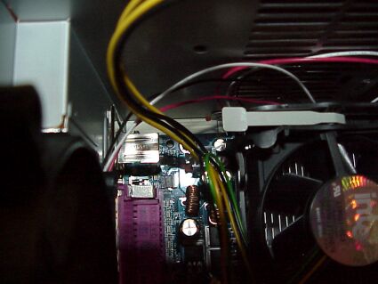
2:00 PM - I found that the ATX_12V plug from the power supply wasn't connected to the motherboard. According to Gigabyte's documentation, this should have prevented the system from starting up. I plugged it in. The system still started up just fine.
AUX_12V cable to motherboard.
2:10 PM - I updated the notes in my journal (and saw wife off on her shopping trip).
Get Tom's Hardware's best news and in-depth reviews, straight to your inbox.
2:40 PM - I traced out the USB connector cables coming from the front panel and tried to figure out how to connect them to the motherboard. I actually grabbed an ohmmeter and ohmed out the connection. Once I was sure I had it correct, I plugged in the cables. When I unplugged them to take pictures of them, I found their markings on the other side of the connectors! Boy, that was a waste of time!
3:00 PM - I put the covers on the case thinking I was finished with all the internal work.
3:10 PM - I noticed the floppy drive LED was on constantly. I had seen this before - the data cable was on backward. How could a keyed cable be installed wrong? I know it was keyed - I saw the key. I removed the covers and disconnected the floppy drive data cable and, sure enough, the cable was on upside down. Don't ask me how, but somehow I managed to plug a keyed connector into its socket upside down.
Current page: Assembling The System, Continued
Prev Page Assembling The System, Continued Next Page Loading The Software