Sponsored by QUE Publishing
Hard Drives 101: Magnetic Storage
Read/Write Heads Designs: Magneto-Resistive Heads
Magneto-Resistive Heads
Magneto-resistive heads, sometimes also referred to as the anisotropic magneto-resistant (AMR) heads, are capable of increasing density four times or greater as compared to the previous inductive-only heads. IBM introduced the first commercially available drive with MR heads in 1991, in a 1 GB 3 1/2-inch model, and other manufacturers quickly followed suit.
All heads are detectors; that is, they are designed to detect the flux transitions in the media and convert them back to electrical signals that can be interpreted as data. One problem with magnetic recording is the ever-increasing desire for more and more density, which is putting more information (flux transitions) in a smaller and smaller space. As the magnetic domains on the disk get smaller, the signal from the heads during reading operations becomes weaker; distinguishing the true signal from the random noise or stray fields present becomes difficult. A more efficient read head, which is a more efficient way to detect these transitions on the disk, is therefore necessary.
Another magnetic effect that is well known today is being used in modern drives. When a wire is passed through a magnetic field, not only does the wire generate a small current, but the resistance of the wire also changes. Standard read heads use the head as a tiny generator, relying on the fact that the heads generate a pulsed current when passed over magnetic flux transitions. A newer type of head design pioneered by IBM instead relies on the fact that the resistance in the head wires also changes.
Rather than use the head to generate tiny currents, which must then be filtered, amplified, and decoded, an MR head uses the head as a resistor. A circuit passes a voltage through the head and watches for the voltage to change, which occurs when the resistance of the head changes as it passes through the flux reversals on the media. This mechanism for using the head results in a much stronger and clearer signal of what was on the media and enables the density to be increased.
MR heads rely on the fact that the resistance of a conductor changes slightly when an external magnetic field is present. Rather than put out a voltage by passing through a magnetic-field flux reversal—as a normal head would—the MR head senses the flux reversal and changes resistance. A small current flows through the heads, and this sense current measures the change in resistance. This design provides an output that is three or more times more powerful than a TF head during a read. In effect, MR heads are power-read heads, acting more like sensors than generators.
MR heads were more costly and complex to manufacture than older TF heads because of the additional components and manufacturing steps required:
- Additional wires must be run to and from the head to carry the sense current.
- Four to six more masking steps are required.
- Because MR heads are so sensitive, they are susceptible to stray magnetic fields and require additional shielding.
Because the MR principle can only read data and is not used for writing, MR heads are really two heads in one. The assembly includes a standard inductive TF head for writing data and an MR head for reading. Because two separate heads are built in to one assembly, each head can be optimized for its task. Ferrite, MIG, and TF heads are known as single-gap heads because the same gap is used for both reading and writing, whereas the MR head uses a separate gap for each operation.
The problem with single-gap heads is that the gap length is always a compromise between what is best for reading and what is best for writing. The read function needs a thinner gap for higher resolution; the write function needs a thicker gap for deeper flux penetration to switch the medium. In a dual-gap MR head, the read and write gaps can be optimized for both functions independently. The write (TF) gap writes a wider track than the read (MR) gap reads. Thus, the read head is less likely to pick up stray magnetic information from adjacent tracks.
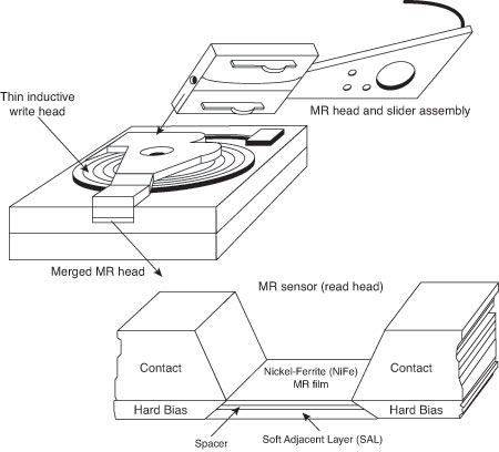
A typical IBM-designed MR head is shown in the figure below. This figure first shows the complete MR head-and-slider assembly on the end of an actuator arm. This is the part you would see if you opened up a drive. The slider is the block device on the end of the triangular-shaped arm that carries the head. The actual head is the tiny piece shown magnified at the end of the slider, and then the MR read sensor in the head is shown further magnified.
The read element, which is the actual magneto-resistive sensor, consists of a nickel-ferrite (NiFe) film separated by a spacer from a magnetically soft layer. The NiFe film layer changes resistance in the presence of a magnetic field. Layers of shielding protect the MR sensor read element from being corrupted by adjacent or stray magnetic fields. In many designs, the second shield also functions as one pole of the write element, resulting in what is called a merged MR head. The write element is not of MR design but is instead a traditional TF inductive head.
IBM’s MR head design employs a Soft Adjacent Layer (SAL) structure, consisting of the MR NiFe film, as well as a magnetically soft alloy layer separated by a film with high electrical resistance. In this design, a resistance change occurs in the NiFe layer as the MR sensor passes through a magnetic field.
As areal densities have increased, heads have been designed with narrower and thinner MR elements. More recent designs have reduced the film width between the side contacts to as little as half a micron or less.
Giant Magneto-Resistive Heads
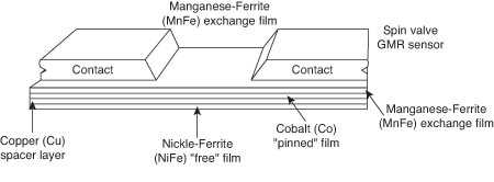
In the quest for even greater density, IBM introduced a new type of MR head in 1997. Called giant magneto-resistive (GMR) heads, they are smaller than standard MR heads but are so named for the GMR effect on which they are based. The design is similar; however, additional layers replace the single NiFe layer in a conventional MR design. In MR heads, a single NiFe film changes resistance in response to a flux reversal on the disk. In GMR heads, two films (separated by a very thin copper conducting layer) perform this function.
The GMR effect was discovered in 1988 in crystal samples that were exposed to high-powered magnetic fields (1000 times the fields used in hard disk drives). Scientists Peter Gruenberg of Julich, Germany, and Albert Fert of Paris discovered that large resistance changes were occurring in materials composed of alternating thin layers of various metallic elements. The key structure in GMR materials is a spacer layer of a nonmagnetic metal between two layers of magnetic metals. One of the magnetic layers is pinned, which means it has a forced magnetic orientation. The other magnetic layer is free, which means it is free to change orientation or alignment. Magnetic materials tend to align themselves in the same direction. So if the spacer layer is thin enough, the free layer takes on the same orientation as the pinned layer. What was discovered was that the magnetic alignment of the free magnetic layer would periodically swing back and forth from being aligned in the same magnetic direction as the pinned layer to being aligned in the opposite magnetic direction. The overall resistance is relatively low when the layers are in the same alignment and relatively high when in opposite magnetic alignment.
The figure below shows a GMR read element.
When a weak magnetic field, such as that from a bit on a hard disk, passes beneath a GMR head, the magnetic orientation of the free magnetic layer rotates relative to that of the other and generates a significant change in electrical resistance due to the GMR effect. Because the physical nature of the resistance change was determined to be caused by the relative spin of the electrons in the different layers, GMR heads are often referred to as spin-valve heads.
IBM announced the first commercially available drive using GMR heads (a 16.8 GB 3 1/2-inch drive) in December 1997. Since then, GMR heads have become standard in most 3.5-inch and 2.5-inch drives.
In 2007 Hitachi developed a giant magneto-resistive head using perpendicular current that supports areal densities of up to 1 Tbits/sq. inch or more. These are called current perpendicular-to-the-plane giant magneto-resistive heads or CPP-GMR for short, and are expected to appear in drives starting in 2011.
Current page: Read/Write Heads Designs: Magneto-Resistive Heads
Prev Page Read/Write Head Designs: Ferrite, Metal-In-Gap, And Thin-Film Next Page Head SlidersGet Tom's Hardware's best news and in-depth reviews, straight to your inbox.
Tom's Hardware is the leading destination for hardcore computer enthusiasts. We cover everything from processors to 3D printers, single-board computers, SSDs and high-end gaming rigs, empowering readers to make the most of the tech they love, keep up on the latest developments and buy the right gear. Our staff has more than 100 years of combined experience covering news, solving tech problems and reviewing components and systems.
-
soccerdocks "Density initially grew at a rate of about 25% per year (doubling every four years)"Reply
If density grows at 25% per year it would actually double in just barely over 3 years. At 4 years it would be 144% greater. -
joytech22 Replywhen passed over magnetic flux transitions.
I somehow expected "Flux capacitors" instead. -
johnners2981 soccerdocks"Density initially grew at a rate of about 25% per year (doubling every four years)"If density grows at 25% per year it would actually double in just barely over 3 years. At 4 years it would be 144% greater.Reply
No you're wrong, how embarrassing :). You're using compound interest. Quit trying to be a smartass -
Device Unknown johnners2981No you're wrong, how embarrassing . You're using compound interest. Quit trying to be a smartassReply
I'm no math guy, in fact i suck at it, but I see his point, why wouldn't it be compound? and even at compound interest is 144 still accurate? please enplane
-
soo-nah-mee I believe soccerdocks is right - example...Reply
Beginning value: 10
After one year: 12.5
After two years: 15.625
After three years: 19.531 (Almost double)
After four years: 24.41 -
johnners2981 Device UnknownI'm no math guy, in fact i suck at it, but I see his point, why wouldn't it be compound? and even at compound interest is 144 still accurate? please enplaneReply
Please enplane??? Compound interest is used to calculate interest and not things like density.
They were right in saying "doubling every four years" and he was trying to correct them when there was no need so showed him who's boss, oh yeah -
johnners2981 soo-nah-meeI believe soccerdocks is right - example...Beginning value: 10After one year: 12.5After two years: 15.625After three years: 19.531 (Almost double)After four years: 24.41Reply
His calculation is right not the application, why is he using compound interest to calculate the percentage increase in density? It doesn't make sense. -
soo-nah-mee johnners2981His calculation is right not the application, why is he using compound interest to calculate the percentage increase in density? It doesn't make sense.It's not compound "interest", but it is compounding. If you say something increases 25% each year, you can't just keep adding 25% of the original value! Silly.Reply
-
striker410 soo-nah-meeIt's not compound "interest", but it is compounding. If you say something increases 25% each year, you can't just keep adding 25% of the original value! Silly.I agree with the others on this one. Since it's adding 25% each year, it is compound. You are thinking of it from the wrong angle.Reply


