How to Design and 3D Print Custom Cases for Your Devices
Design your own products with free software and 3D printers
3D printers are exciting pieces of technology. We can create objects from reels of plastic filament. These objects are commonly toys or trinkets, found on sites such as Thingiverse or Printables. But what if we had an object, such as a Raspberry Pi, a custom electronics project or even a mobile device and we wanted to make a case for it? If nobody else has made a free STL file available, we need to be able to design and make our own 3D printed case.
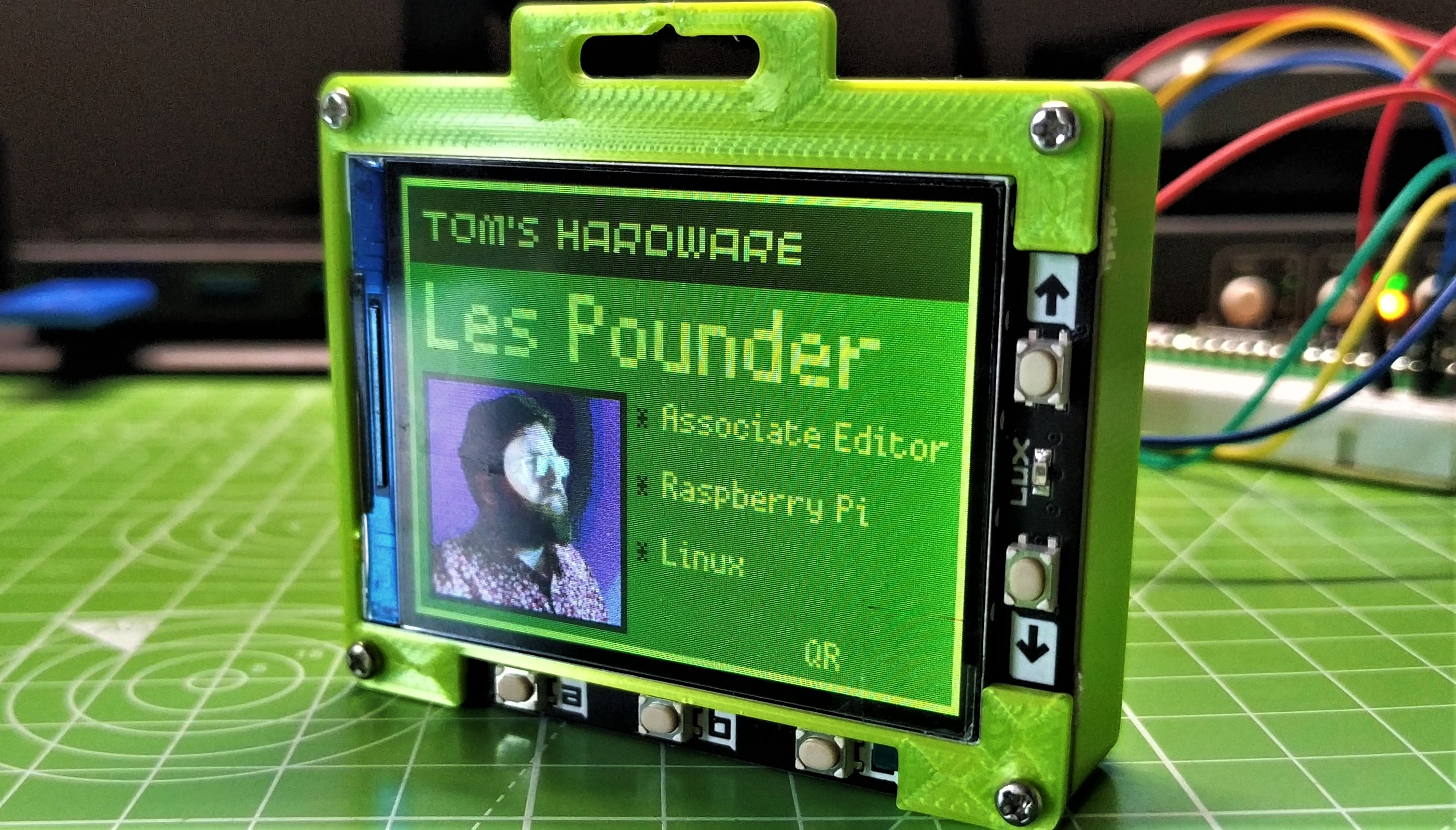
In the tutorial below, we’re going to learn how to custom design and 3D print a case by creating one for the Pimoroni Tufty2040, an RP2040-powered badge with a 2.4-inch LED screen. I wanted to wear the Tufty2040 to a conference, but when I went to look, there weren’t any cases available for it. So I set out to make an enclosure with holes for a lanyard and the USB-C port, along with enough space to hold a 1,000 mAh LiPo battery and protect all the internal components.
Designing your own product for 3D printing is relatively straightforward. We just need to apply an iterative methodology to the design and fabrication process. During the process, we will have many failures. In designing a box for the Tufty2040, we created five versions of the case before we got it right. Each failure is an opportunity to learn something new. In fact our first failure became a prototype. It forced us to rethink how we designed the top layer, enabling access to the buttons while offering protection for the large LCD display.
The process will differ slightly depending on what you are creating a case for. However,in following the steps for the Tufty2040, we’ll learn the basic steps for creating and 3D printing a custom case.
For this project you will need
- 3D Printer
- Tufty2040 (or other device that you wish to design for)
- Ruler / digital calliper
- Safely charged LiPo battery
- M2 18mm Machine Screws and Nuts
Getting the Measurements
The first thing we need to do is to work out the dimensions of the object. If we have the object in our hands, we can measure it using a ruler and this will give us a fair approximation of its dimensions. A more precise means of measurement are digital calipers which we can use to accurately measure the internal and external dimensions of the object.
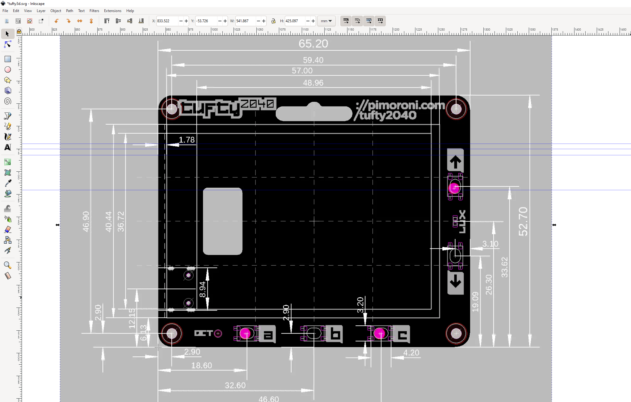
Sometimes the creator of the object will provide a mechanical drawing, and this is the ideal scenario. From the mechanical drawing we can trace the dimensions.
1. Download the mechanical drawing to your machine.
Get Tom's Hardware's best news and in-depth reviews, straight to your inbox.
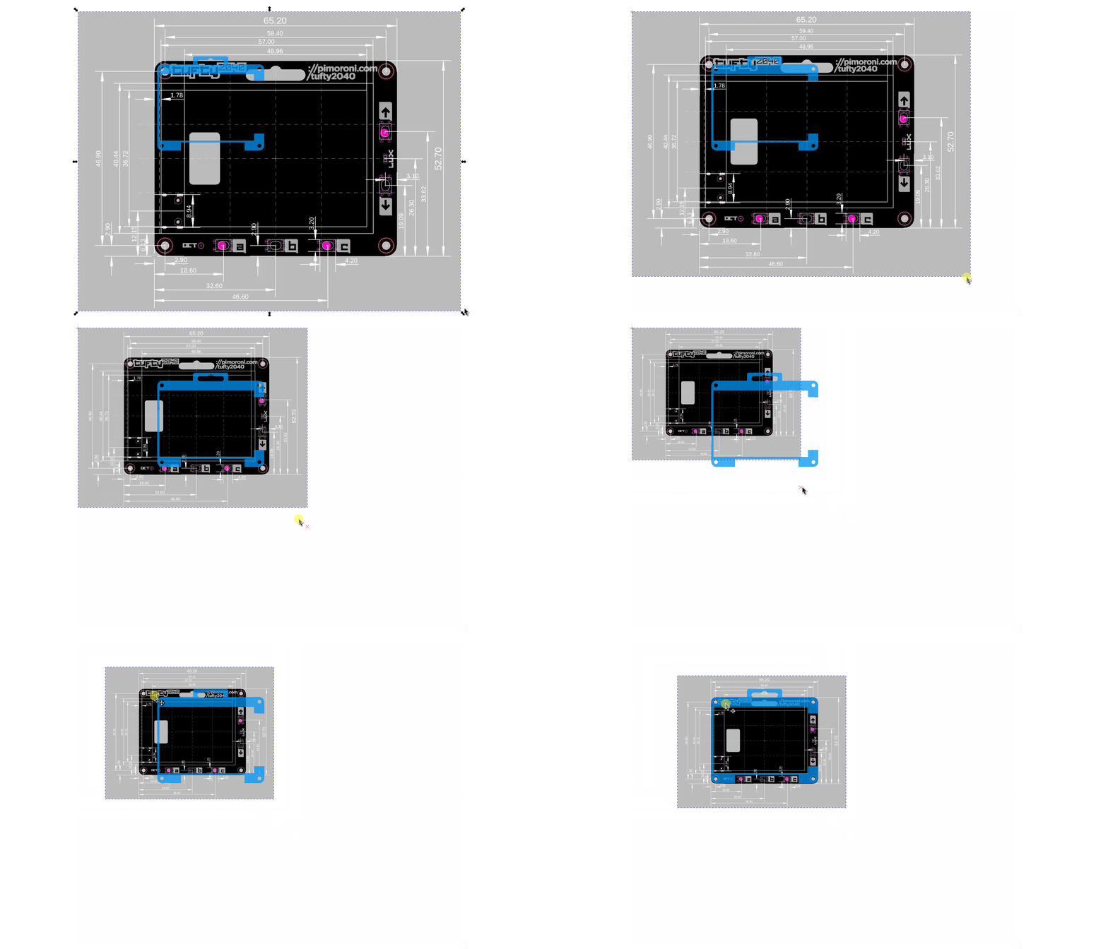
2. Open a vector image editor, such as Adobe Illustrator or Inkscape. We used Inkscape as it is free, and more than capable for the job.
3. Import the mechanical drawing into Inkscape.
4. Select the rectangle tool.
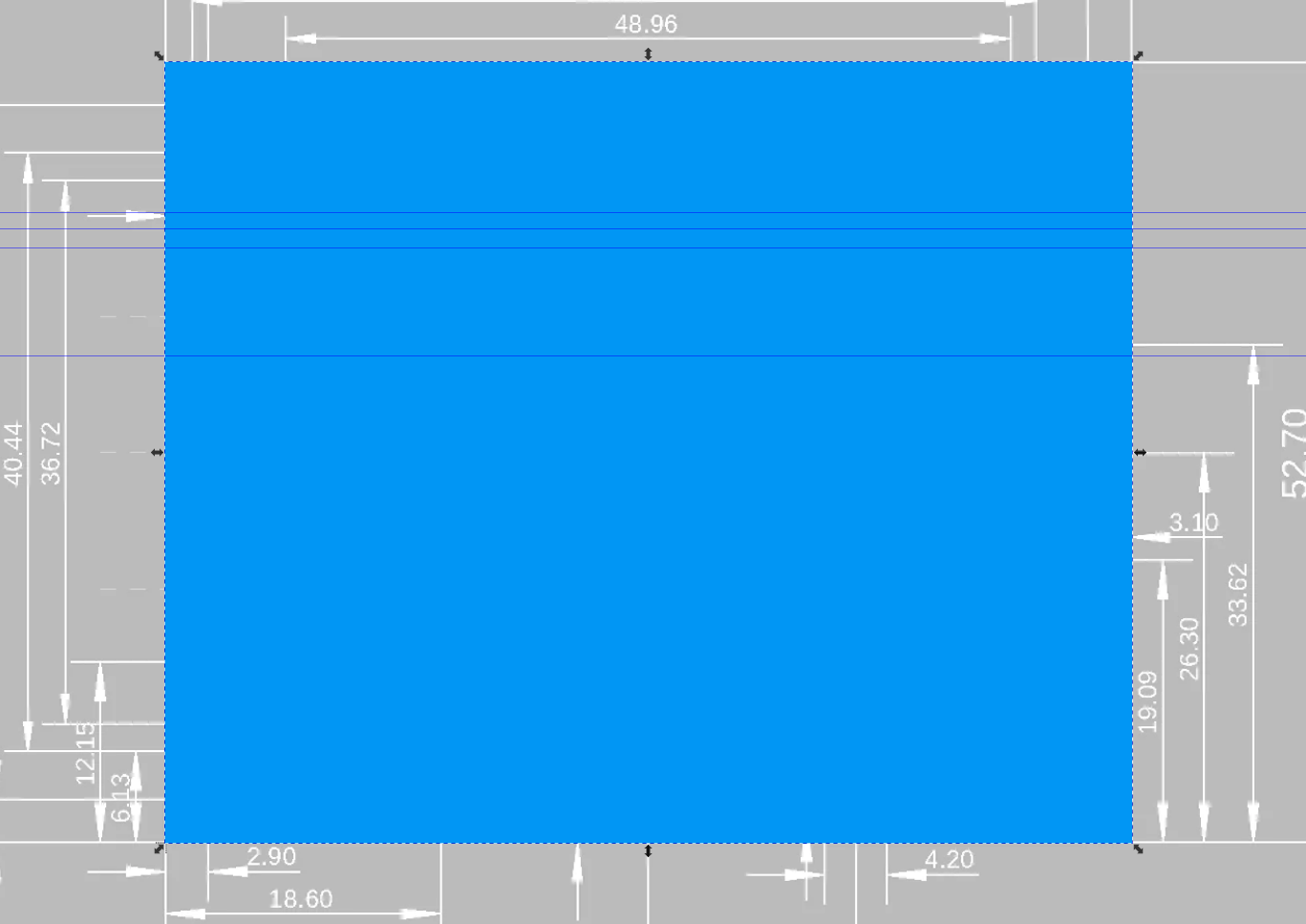
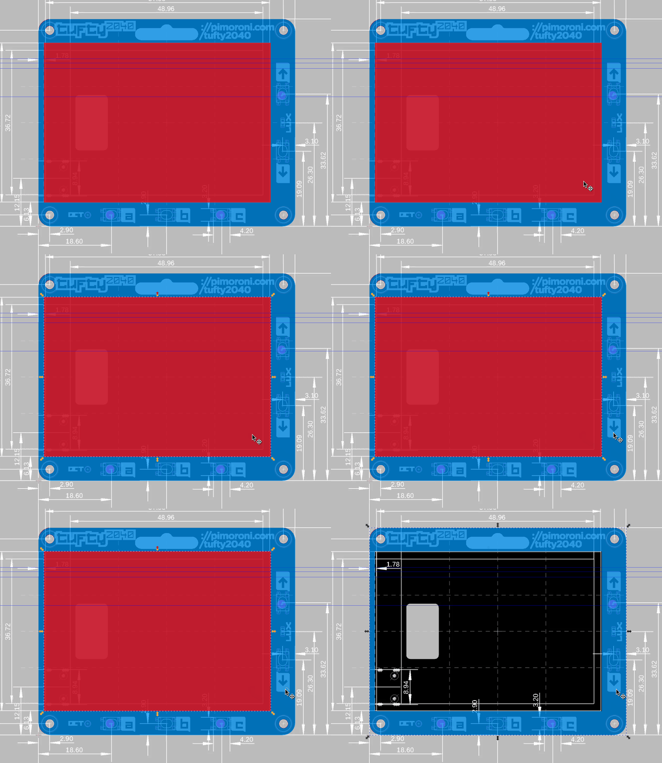
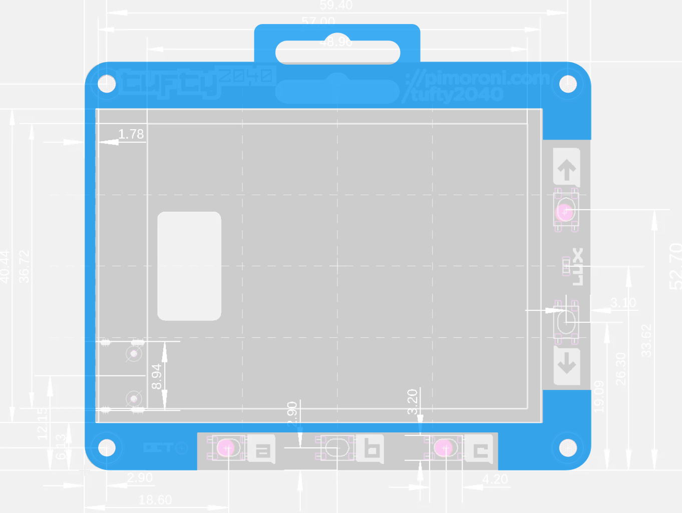
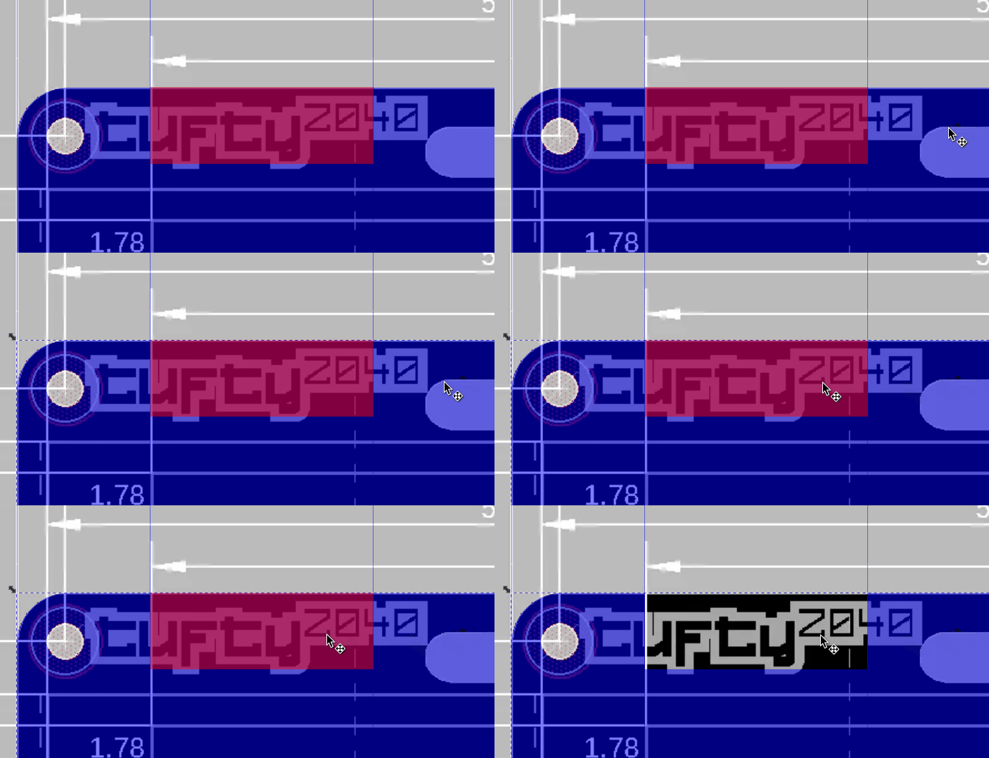
5. Trace the outer edge of the board using a rectangle, use a bright color for the trace. You don’t need to be super precise right now, just get the basic size right.
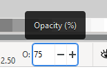
6. Change the opacity of the rectangle so that the mechanical drawing is visible. The opacity tool is located in the bottom left of the Inkscape user interface. Around 75% opacity is perfect but change this to suit your preference.
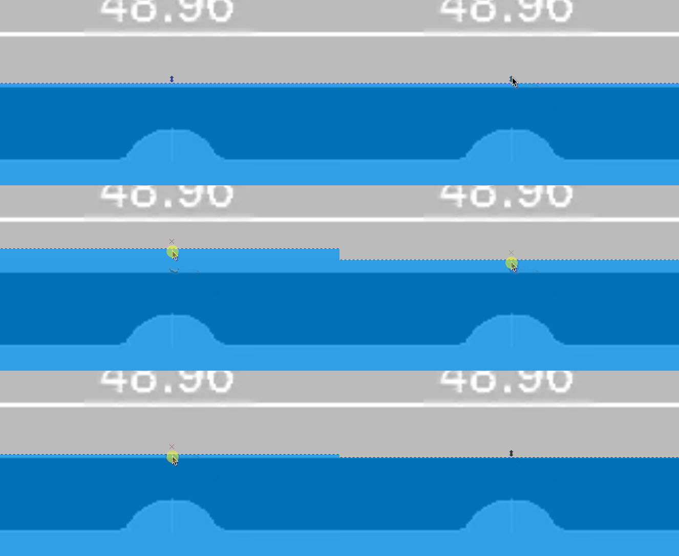
7. Using the arrows around the rectangles perimeter, tweak the size of the trace so that it matches the outline exactly. Use CTRL + scroll wheel to zoom in and out to get a better level of accuracy.
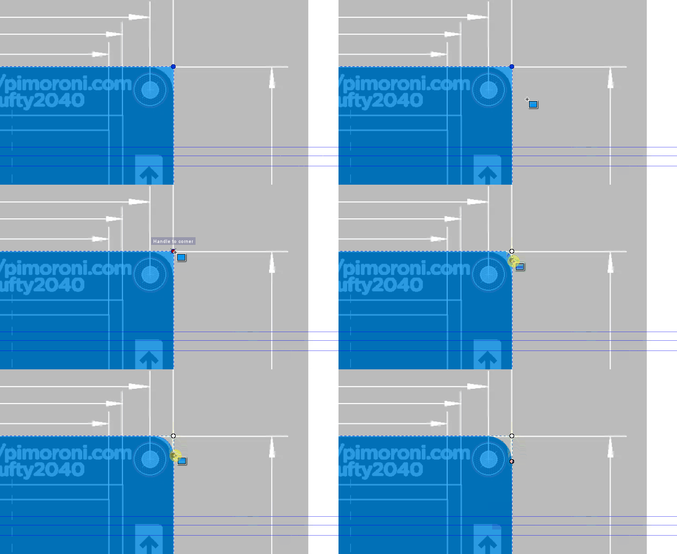
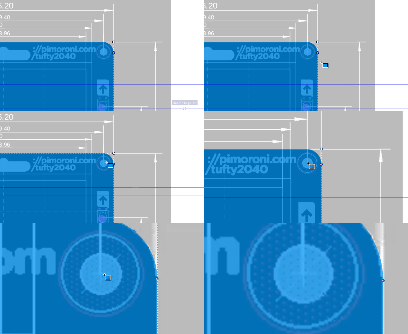
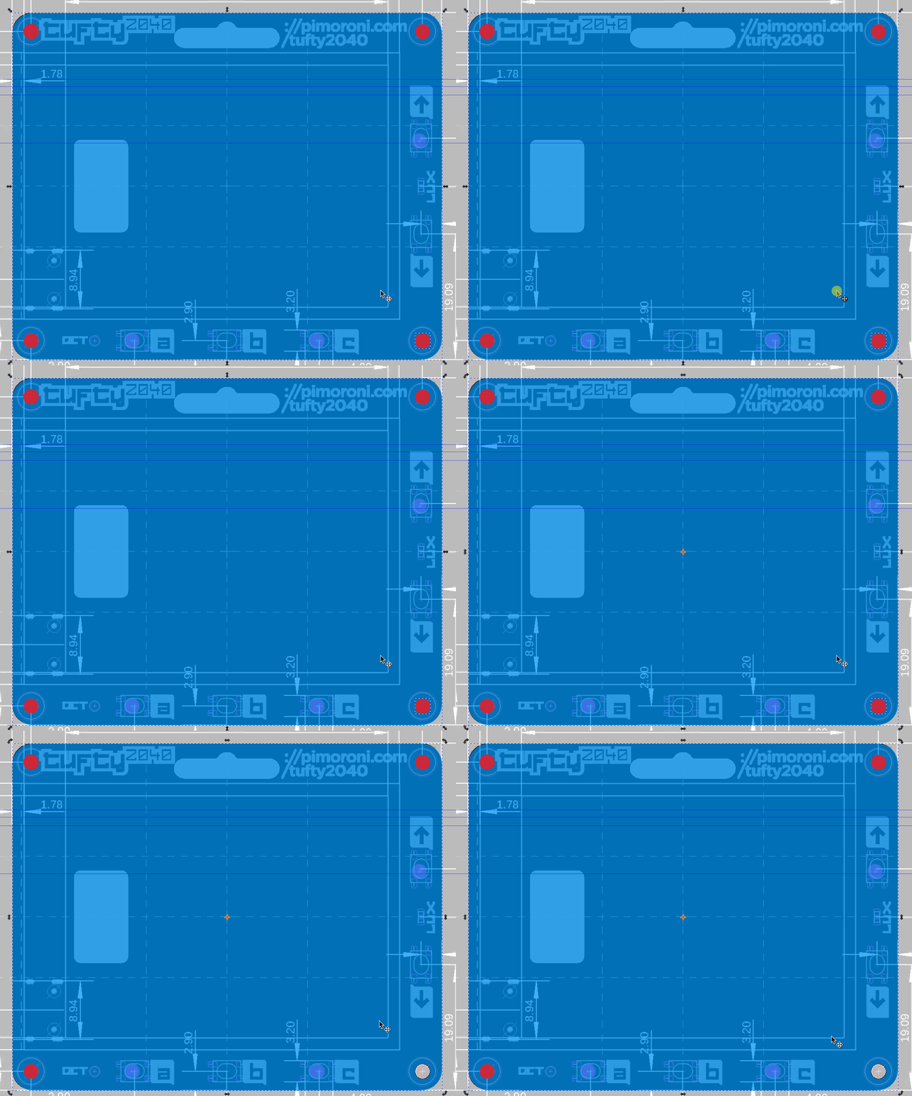
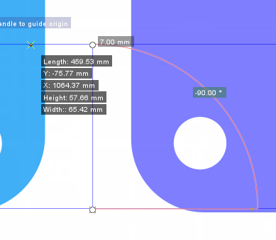
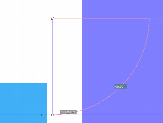
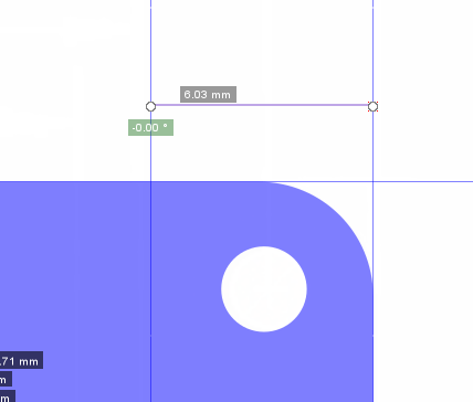
8. Select the rectangle tool and look to the top right of the trace. Left click and hold on the circle and drag until the radius matches that of the board. By doing this to one corner, the others are also set.
9. Zoom in to the top right corner by holding CTRL and using the scroll wheel of your mouse.
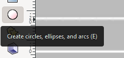
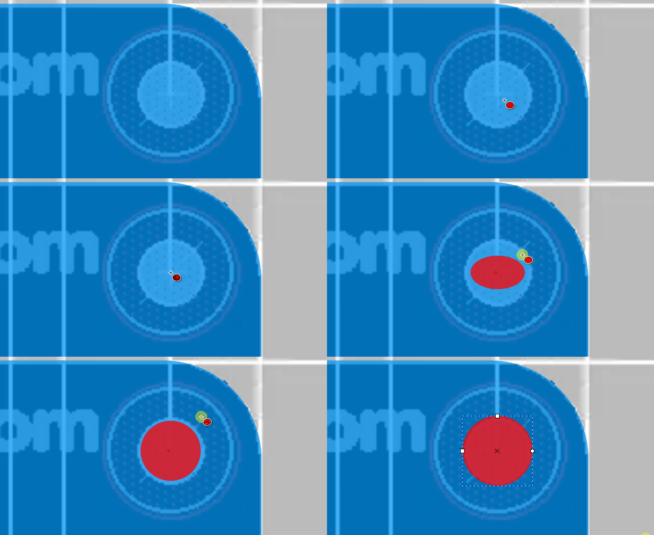
10. Select the circle tool and set the fill color to red.
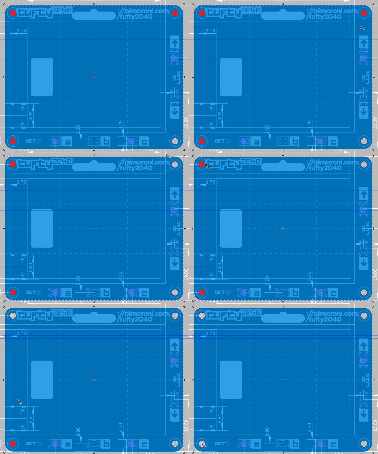
11. In the center of the top right circle of the traced board, draw a circle by holding SHIFT and CTRL, then left click and drag until the circle fills the inner circle. This will create a red circle which we shall use to cut a hole in the board.
12. Repeat step 11 for the three other corners. These circles will be M2 (2mm diameter screws) screw holes that will be used to sandwich the board to the 3D print layers. you can duplicate the original circle (CTRL + D) and drag them to each corner, you may need to tweak their size.
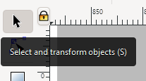
13. Select the Select tool from the tools menu.
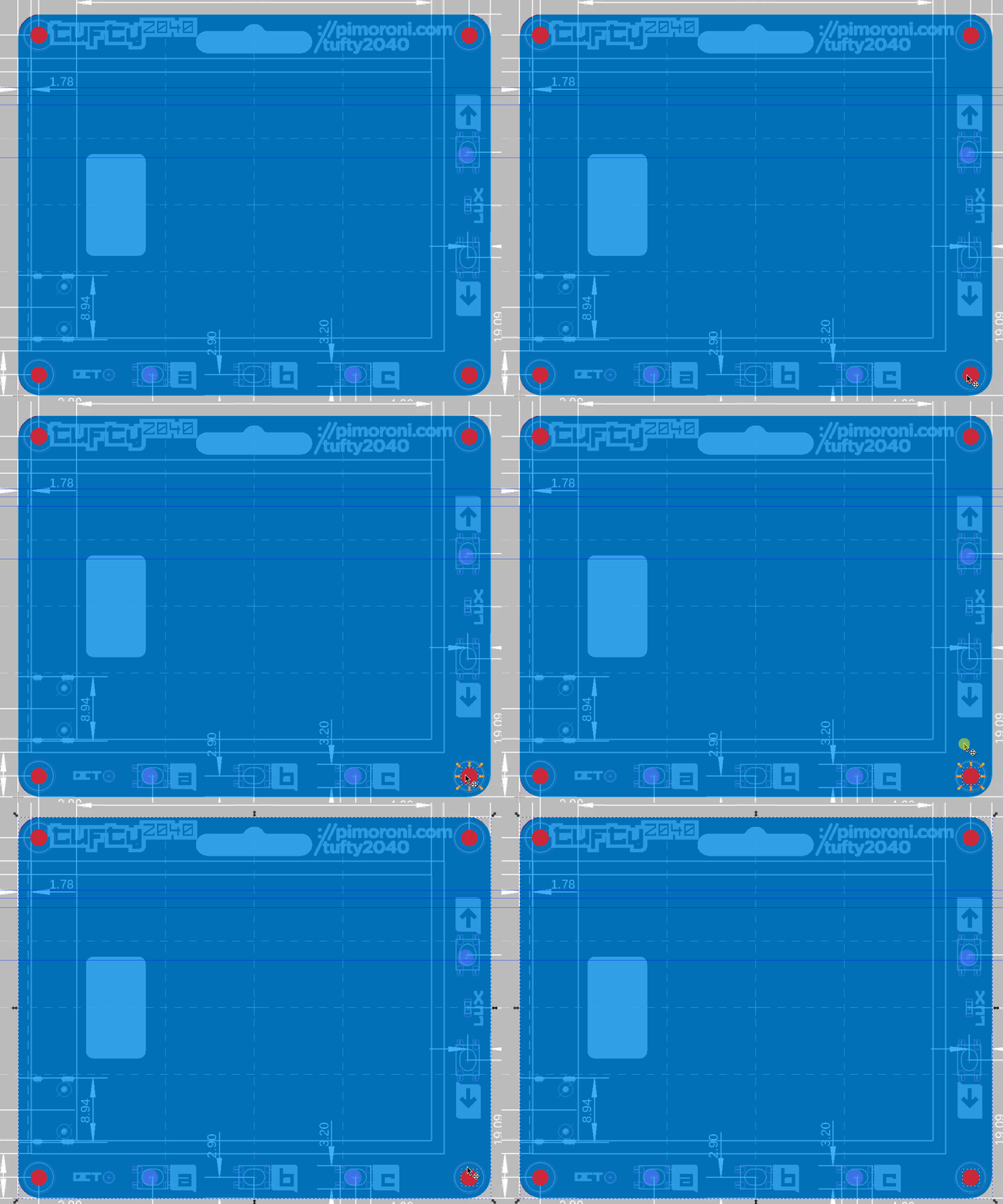
14. Select one of the circles, and then press SHIFT and select the trace. This will select both objects.
15. From the Path menu select Difference (alternatively press CTRL + -) to cut the circle from the traced rectangle.
16. Repeat the previous step for the remaining circles.
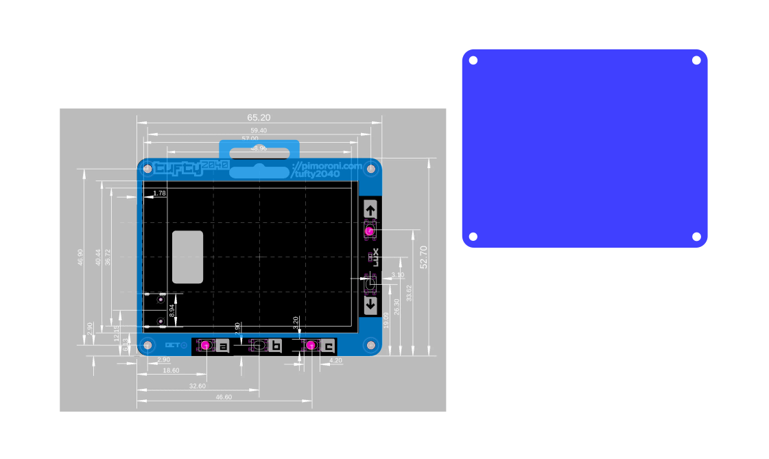
17. Select the traced board and press CTRL + D to duplicate the shape. Put the shape somewhere safe. This shape will later become the rear panel of the case.
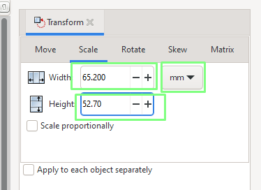
18. Click on the rear panel and then click on Object >> Transform menu (SHIFT + CTRL + M).
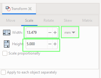
19. Set the size of the rear layer so that it matches the values given in the mechanical drawing. Click Apply to set the dimensions. In this case the panel needs to be 65.20 by 52.70 mm.
20. Repeat the process for the front panel so that it matches the dimensions of the rear panel.
21. Manually rescale the mechanical drawing using the perimeter arrows.This will take time but is worth the effort.
Cutting Out The Screen and Buttons
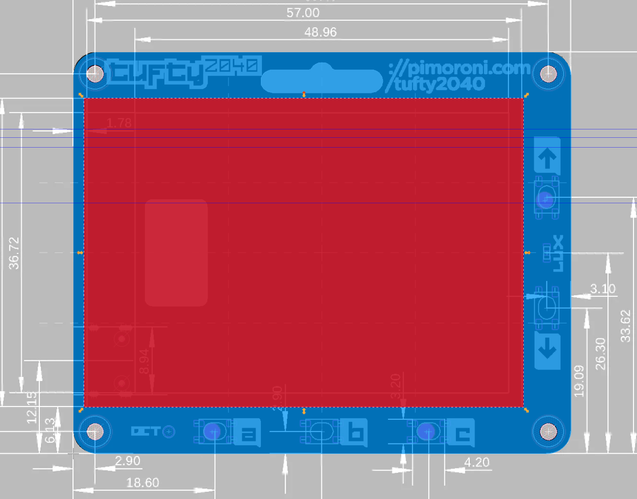
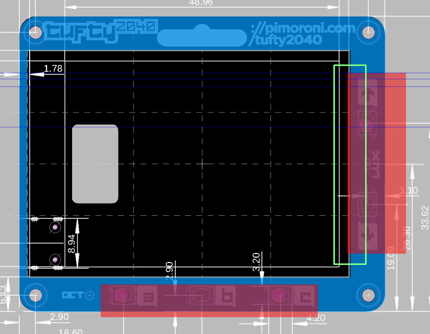
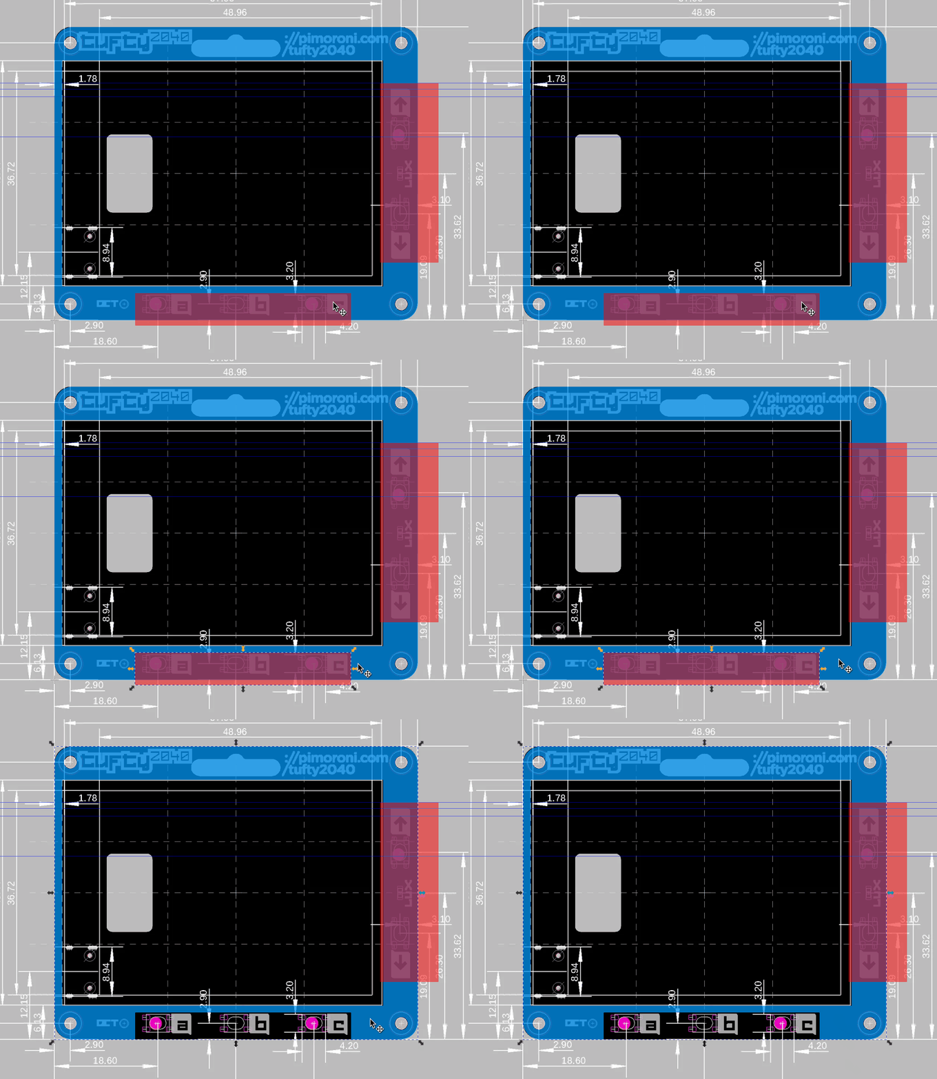
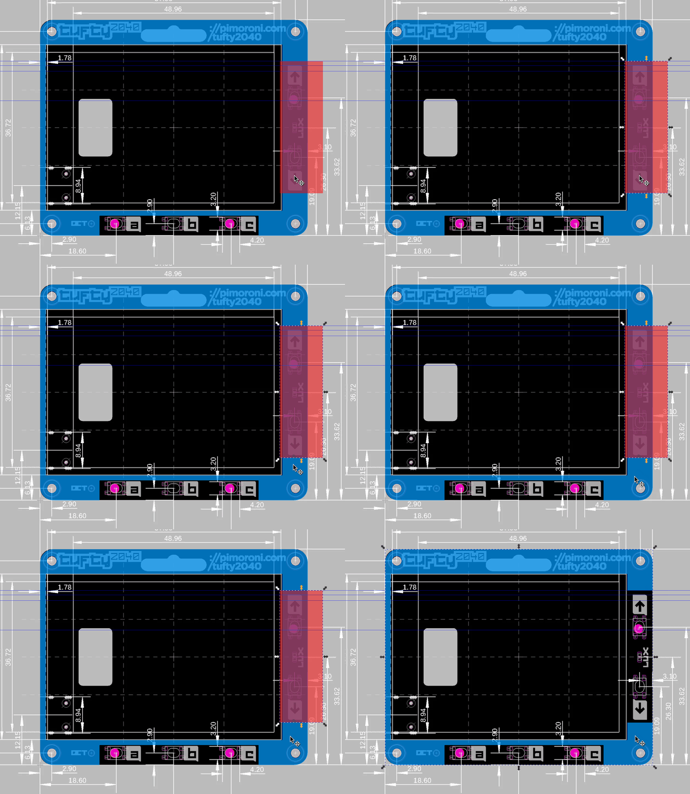
The next part of the design process is to cut out access points for the five buttons and a large cutout for the screen. We can approach this in a number of ways. We can meticulously cut out the sections around the points of access, or we can create a larger cutout for all. The latter is the preferred method if we choose to follow the dimensions of the board.
If we were to cut out around the buttons and keep the same dimensions, we would have very little plastic on the perimeter of the buttons. This leaves them vulnerable to breakage. If we were to create a larger case, say an additional 5mm around the perimeter, then individual button cutouts would look much better.
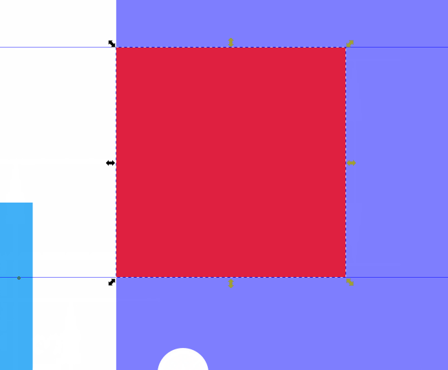
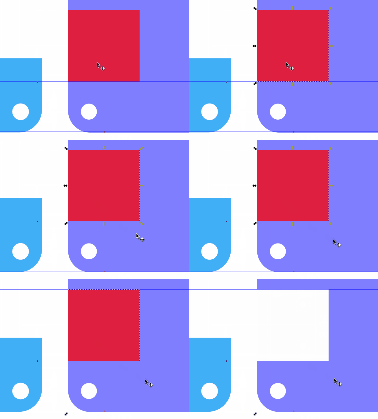
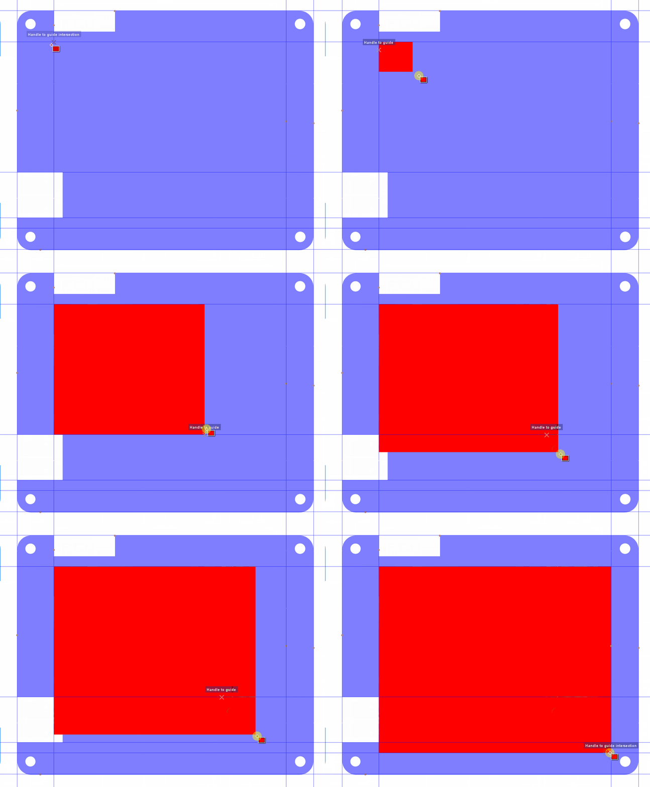
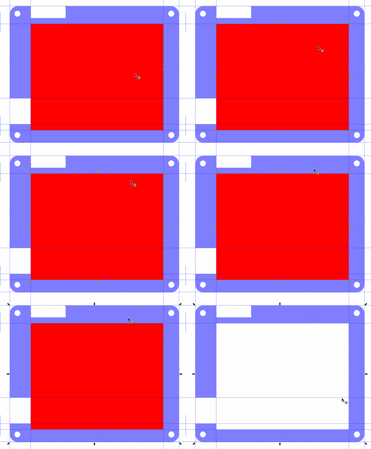
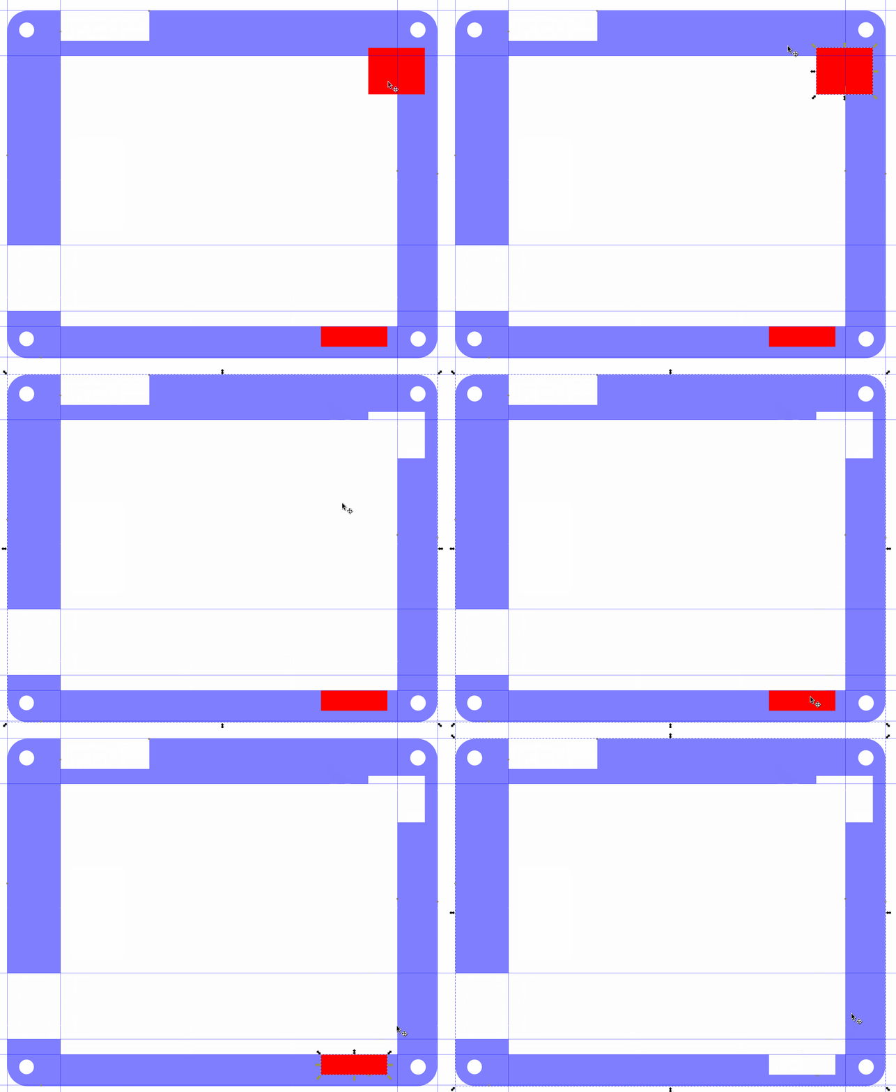
1. Using the rectangle tool, create a cut out for the screen. Be a little more generous with the cut as we need the screen to be secure, but with little or no pressure as it could cause damage.
2. Select the rectangle and the traced board and then use Path >> Difference (or CTRL + -) to cut the screen from the traced board. If you are not happy with the cut, undo the cut (CTRL + Z) and resize the rectangle, then try again.
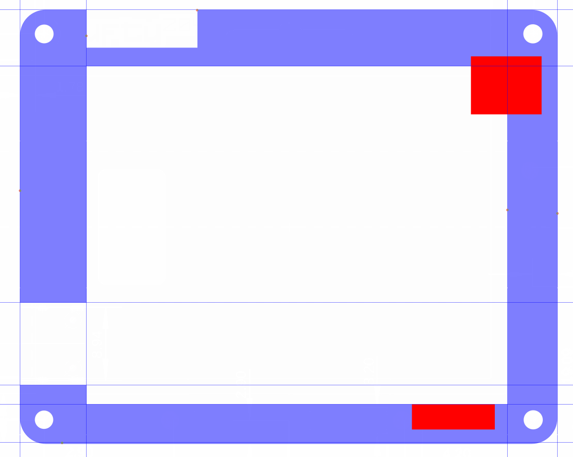
3. Add two more rectangles for the buttons. The right-side arrow buttons have their cut out overlapping the screen cut out. This is deliberate. We tried leaving a little plastic between the screen and buttons, but it was too fragile.
4. Select one button rectangle and the traced board and then use Path >> Difference (or CTRL + -) to cut the screen from the traced board. If you are not happy with the cut, undo the cut (CTRL + Z) and resize the rectangle, then try again.
5. Repeat the cut for the remaining button cut out.
Adding A Lanyard Hook
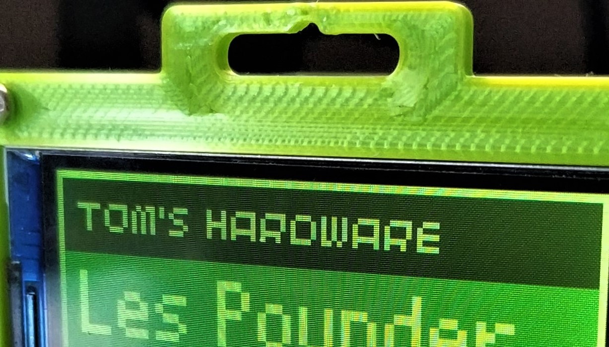
Tufty 2040 has its own hook for a lanyard. The problem is that it will be too fragile if we cut it out of the existing frame. We’re going to add a little more meat to the top of the frame, and then cut into it to create a lanyard hook.
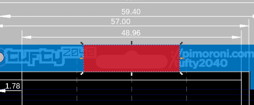
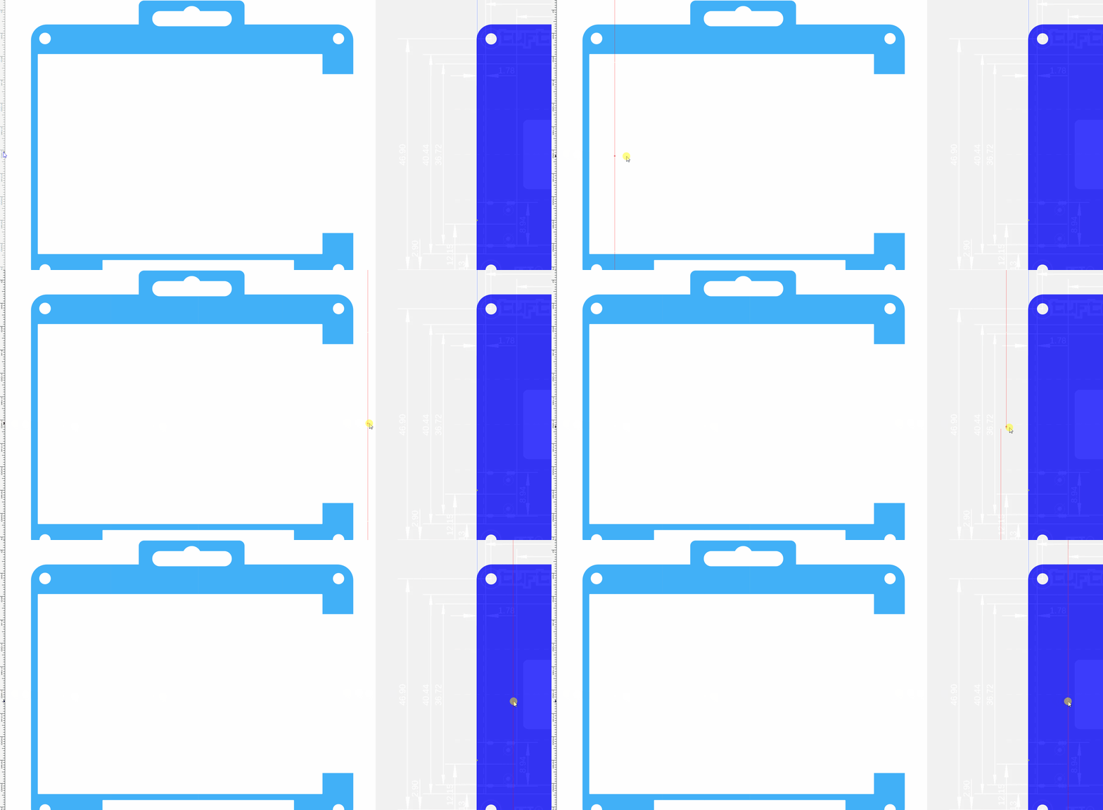
1. Draw a rectangle which is wider and taller than the existing lanyard hook.
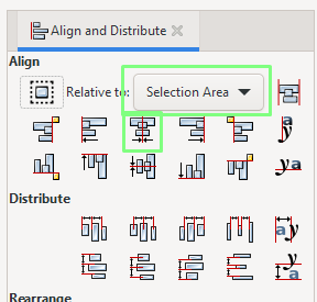
2. Select the traced board and the new rectangle. Then go to Object >> Align and Distribute (SHIFT + CTRL + A). Look to the top right corner and a new menu appears
3. Ensure that “Selection Area” is highlighted, and then click Center on Vertical Axis. This will force the two shapes to center align, necessary to balance the frame on a lanyard.
4. Move the rectangle so that it slightly overlaps the traced board. We need to move it away from the board but keep enough overlap to ensure a strong bond.
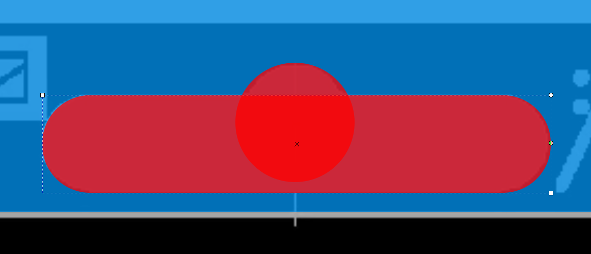
5. Select the rectangle, and then using the rectangle tool, change the corner radius so that it is similar to the traced board. Watch out! Sometimes the corner radius may cause an unwanted “cut” between the sharp line of the traced board and the lanyard hook.
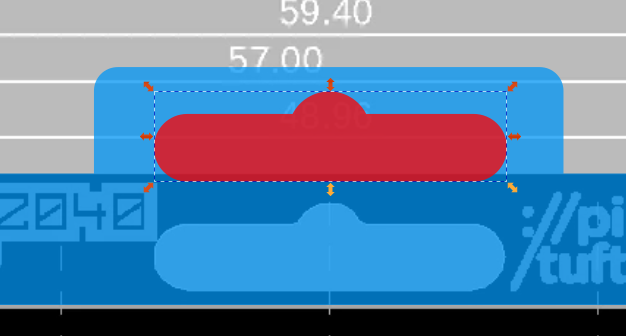
6. Combine the rectangles using Path >> Union (CTRL and +). This creates one shape.
7. Using the rectangle and circle tool, trace the lanyard hook shape. Change the radius to match that of the trace.
8. Combine the shapes using Path >> Union (CTRL and +).
9. Move the lanyard hook up the frame. Remember to leave enough space between the edge and the hook. More space gives us more strength.
10. Cut the lanyard hook from the trace by selecting both shapes and using Path >> Difference (CTRL + -).
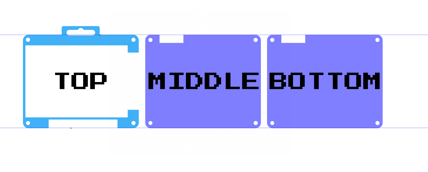
After all of this work we should have the top panel completed.
Creating the Bottom Panel
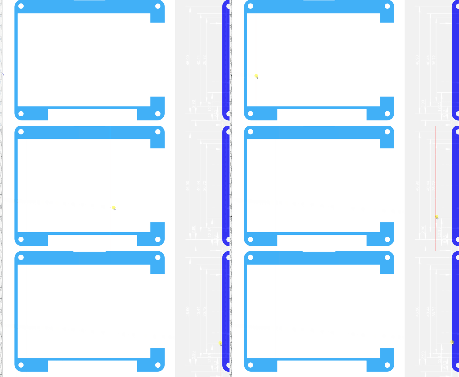
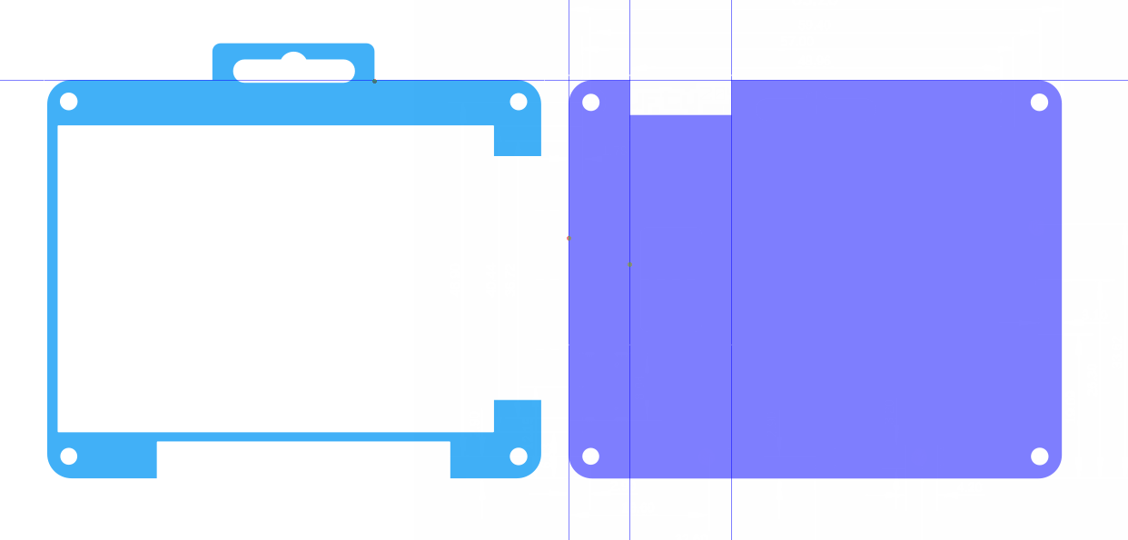
The bottom panel is extremely simple to make. We already have the basic outline, which matches that of the front panel. The only thing that we need to do is to make a cut out so that we can access two buttons on the rear of Tufty 2040.
As we look at the bottom panel, we are looking “top down” at its footprint. The layer visible to us will be the inside of the layer. This means that the cut out should be on the top left of the panel.
1. Take a ruler / digital calliper and measure the distance from the left edge to the first button. Make a note of the distance.
2. Measure the distance from the far edge of that button to the far edge of the next button. Make a note of the distance.
3. Move the front panel piece out of the way, and place the rear panel on top of the mechanical drawing. Make sure that everything lines up.
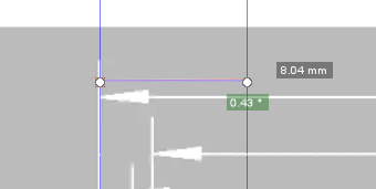
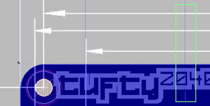
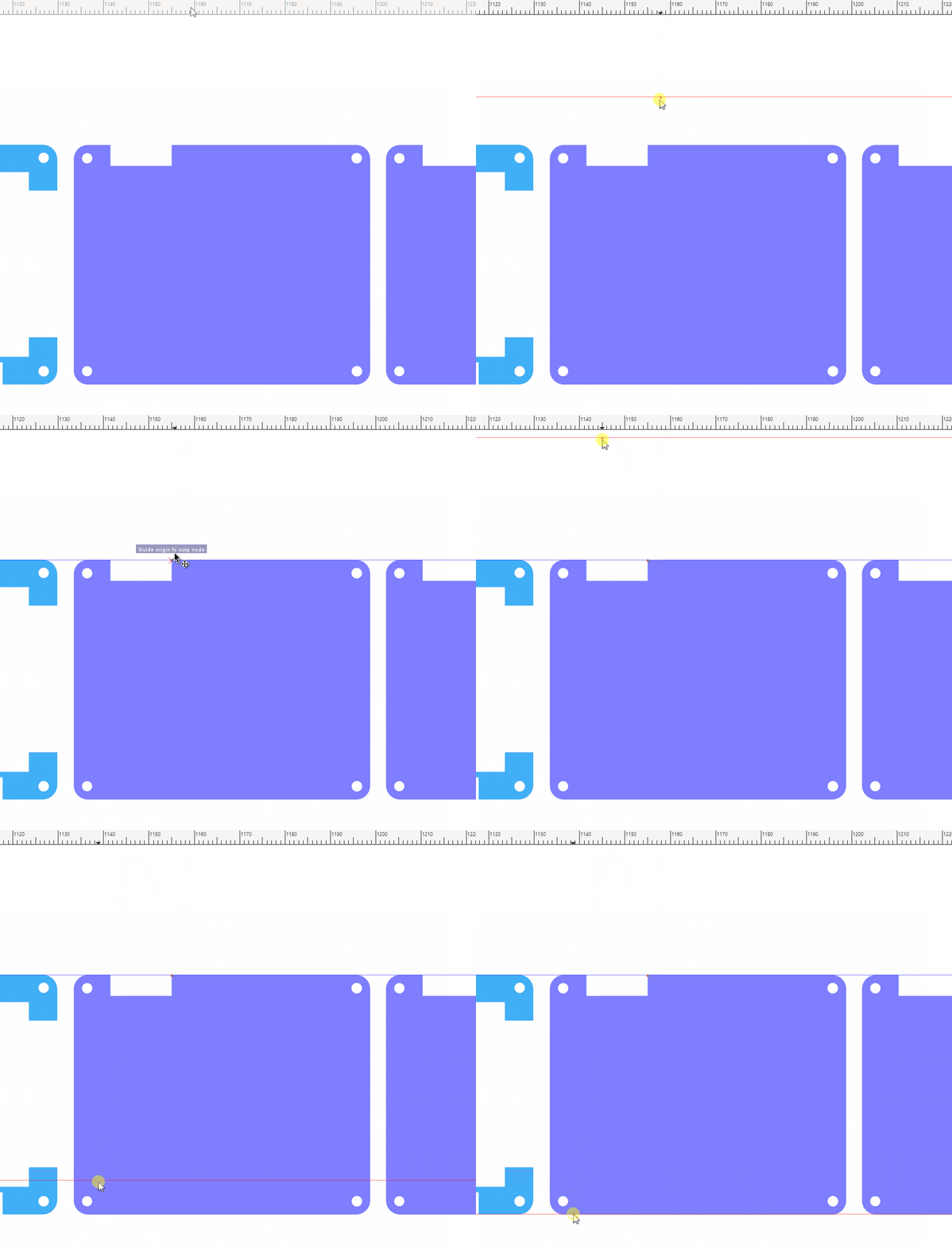
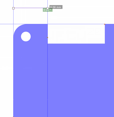
4. Go to the far left and look for the vertical ruler. From there, left click and drag. A guide line will appear. Place the guide line inline with the left edge of the rear panel.
5. Draw another guide, to the right of the first. It only needs to be a short distance away.
6. Use the measurement tool (bottom tool icon) to measure the distance between the two guide lines. In our measurement, it was 8mm from the left edge to the first button.
7. Drag the guide and remeasure until you get the correct measurement.
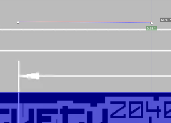
8. Drag another guide and place it to the right of the second guide.
9. Drag the guide and keep measuring until the distance between the second and third guide matches the distance required. In our measurements, the distance from the far side of one button to the far side of the other was approximately 12mm, so we used 13mm to include a margin of error.
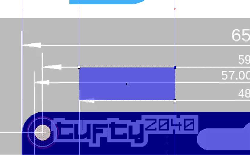
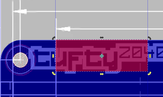
10. Draw a rectangle between the second and third guides. The width has to connect the two guides, the height is not important right now.
11. Click on the rectangle and then click on Object >> Transform menu (SHIFT + CTRL + M).
12. Keep the width as is, change the height to 5mm and click Apply.
13. Move the rectangle until it overlaps the layer.
14. Click on the rectangle and the layer (Shift + Left Click) then press CTRL + - to cut the rectangle from the layer.
We now have two layers, top and bottom. All that is left now is to create a middle layer.
Creating the Middle Layer
The middle layer is the most complex of the three layers. It shares the same outline as the front and back layers, but we need to make a series of cuts to the inner perimeter of the frame. Cuts that will enable us to make space for components, connections and a LiPo battery.
1. Duplicate the bottom layer and keep the original somewhere safe. You should now have three layers, top, middle and bottom. We only need the middle layer for now.
2. Our first cut is for the USB C connector. Measure the distance from the bottom left of the frame to the USB C port. Our measurement was approximately 8mm.
3. Bring two guides from the top ruler and place one at the base, and another at the top of the middle layer. Make sure they are exactly in place.
4. Draw another guide and place it 7mm from the bottom guide. Use the measure tool (bottom left of toolbox) to verify the distance. Remember that the guide can be moved to get a precise measurement. Check the measurement and tweak the distance until happy. We reduced the distance to 7mm to give us 1mm around the USB C connector, and for any errors.
5. Add another guide, above the previous and measure 10mm from there using the measure tool.
6. Using the rectangle tool, draw a 10mm square and place it on the edge of the middle layer between the two guide lines.
7. Select the square and the middle layer (Shift click) and select Path >> Difference (CTRL + -_ to cut the square from the middle layer. This gives us a cutout for the USB C port.
8. Bring two vertical guides into the project, line the first to the left side of the middle layer, the other set 8mm into the layer. This will set the boundary of an internal perimeter for a cut.
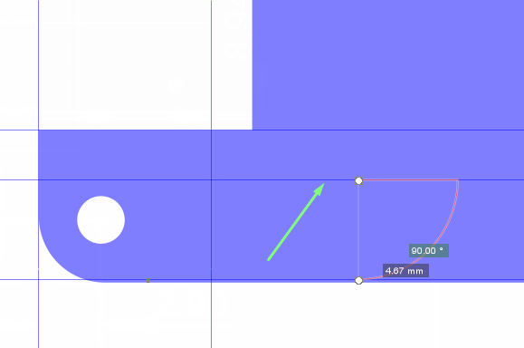
9. Add another horizontal guide at the bottom left of the layer. Measure around 4.5 - 4.6mm and move the guide to that position. This sets the bottom perimeter of an internal cut.
10. Bring two more vertical guides in and place the first on the right side of the middle layer. The other should be 6mm inside the middle layer. Again this is creating an internal perimeter.
11. Add another horizontal guide, under the top most horizontal guide, and measure approximately 6.8 - 7mm from the top guide. This is the final internal perimeter for the cut.
12. Using the internal perimeter, draw a rectangle which touches every part of the perimeter. This will be the internal cut.
13. Select the rectangle and the middle layer then use Path >> Difference (CTRL + -) to cut the internal perimeter out of the layer.
14. Add two more rectangles, the size of which is a little bit of guesswork right now. Approximate the rectangles, we will fine tune them in the 3D model. These are cutouts for components on the Tufty 2040 board. If we don’t cut out these shapes, the layers will not sit flush.
15. Select a rectangle, then the layer and cut the rectangle out using Path >> Difference. Repeat for the second rectangle.
16. Save each layer as its own SVG file (Tufty2040Front.svg, Tufty2040Middle.svg, Tufty2040Bottom.svg).
Editing the Layers in 3D with Tinkercad
Tinkercad is a free and simple to use online tool which enables anyone to make 3D objects for printing. It may not have the same level of features as AutoCAD or FreeCAD, but for most maker projects it has enough to get the job done.We are going to use Tinkercad to import our SVG files and convert them from 2D illustrations, into 3D models that our 3D printer can print.
1. Login or create a new account on Tinkercad. Tinkercad is a free, online, 3D design tool which we can use to convert SVG files into 3D objects.
2. Click on Create New Design.
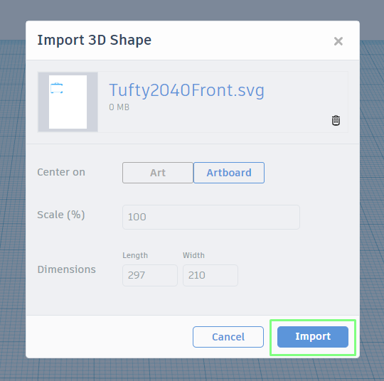
3. Click on Import then import Tufty2040Front.svg.
4. Click on Import to accept the default options.
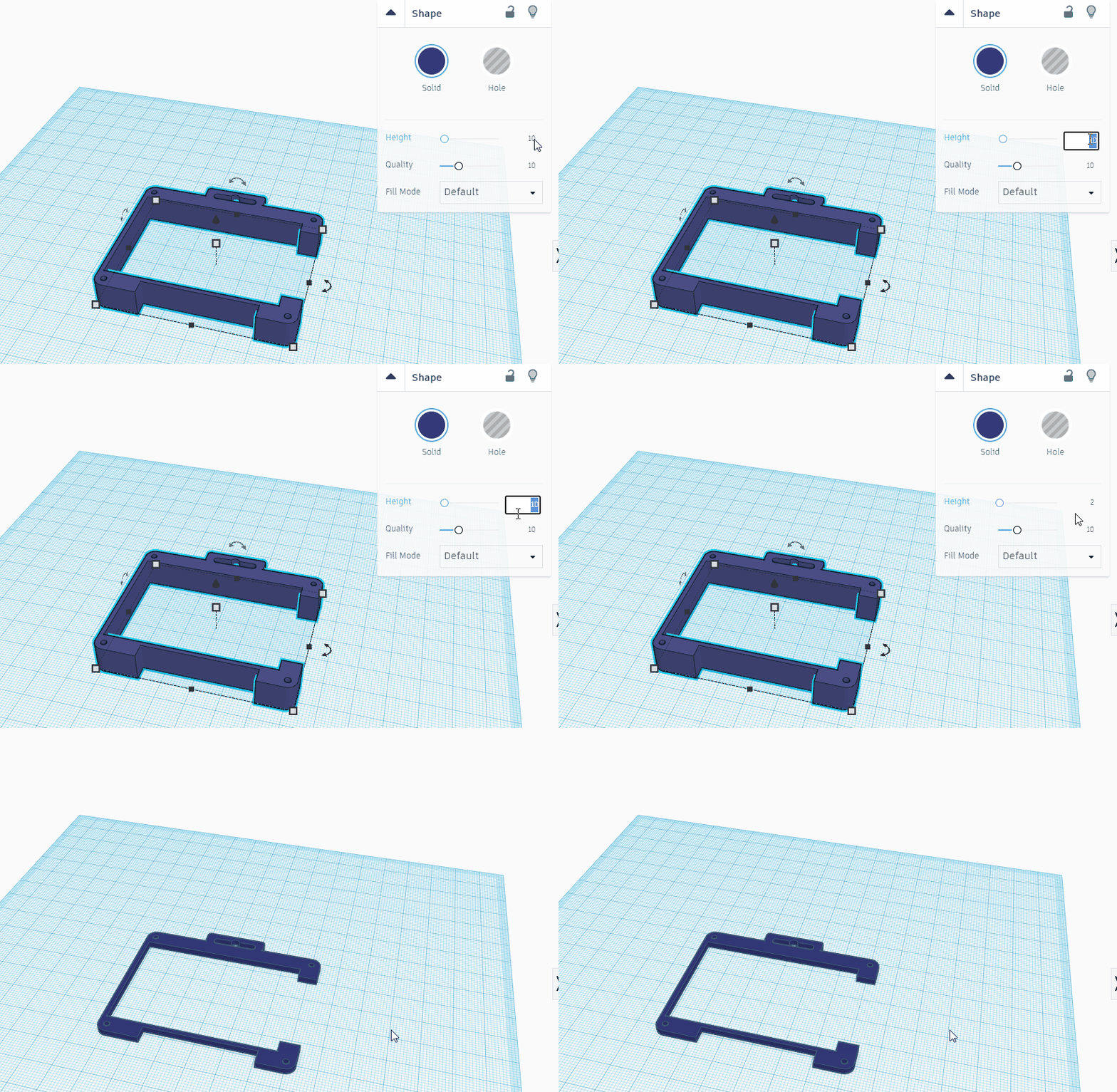
5. In the top right of the workspace, use the height slider to change the height of the front layer; it needs to be 2mm thick. This is just thick enough to remain rigid, but thin enough to print quickly.
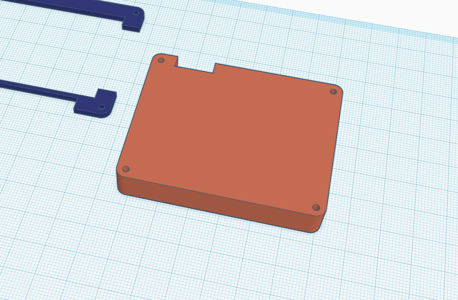
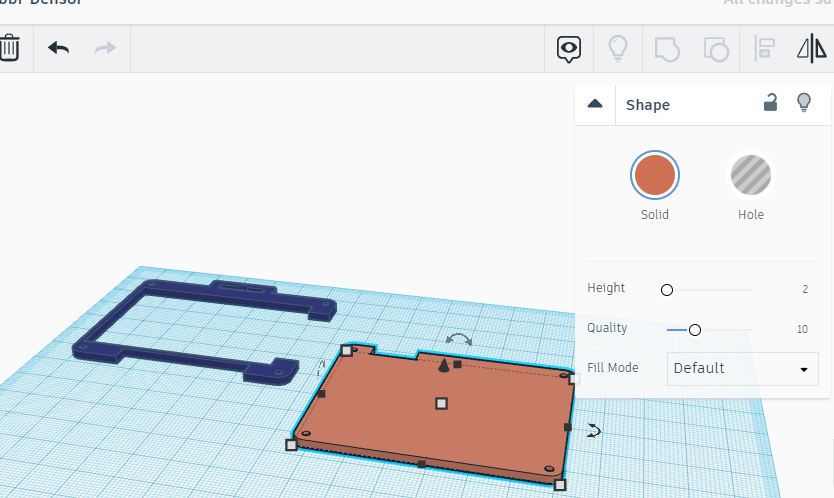
6. Import the bottom layer (Tufty2040bottom.svg) into the workspace.
7. Use the height slider to set the height to 2mm. By default, Tinkercad sets the height to 10mm, which is way too thick for this project.
Tweaking the Middle Layer
The middle layer is where we have to do the most work. The cutouts created in Inkscape are just some of the amendments needed to fix the layer around Tufty2040’s components.
1. Import the middle layer (Tufty2040Middle.svg) into the workspace.
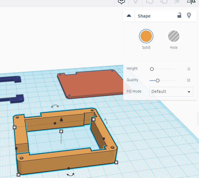
2. Change the height of the middle layer to 11mm. In order to safely contain a LiPo battery, we need to gently hold it in place, not force it down onto the components.
3. Use the scroll wheel to zoom in, and the left mouse button to position the middle layer in the center of the screen. The right mouse button will rotate the workspace for a better view. We need to make two “cuts” into the frame, for better compatibility with the surface mount components present on Tufty2040.
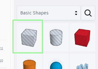
4. From the right side menu, select the hollow cube and drag it into the workspace.
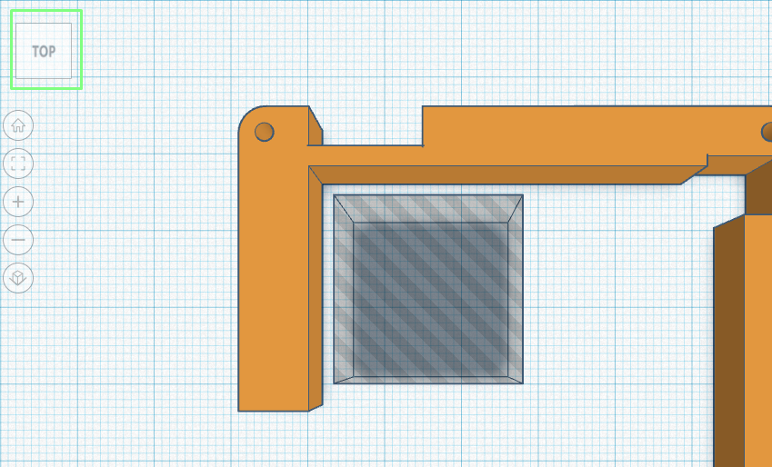
5. Click on Top (top left icon) to set the view to an above perspective.
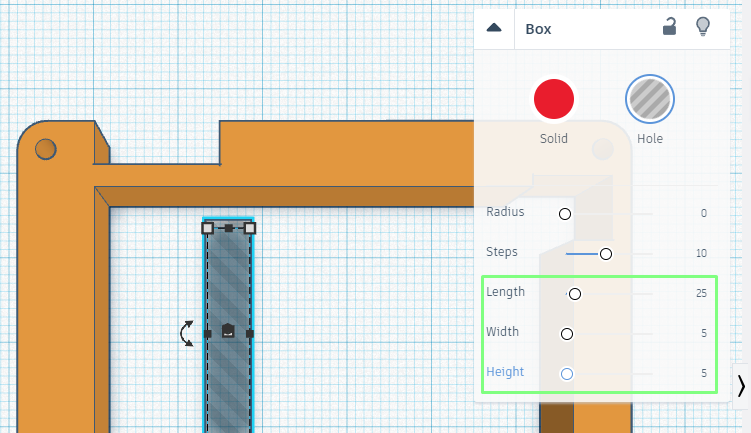
6. Click on the hollow cube and adjust the length to 25, width to 5 and height to 5mm.
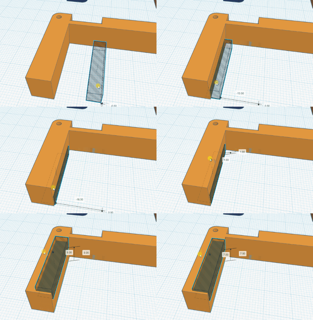
7. Using the right mouse button, rotate the view to clearly see the left side of the middle layer.
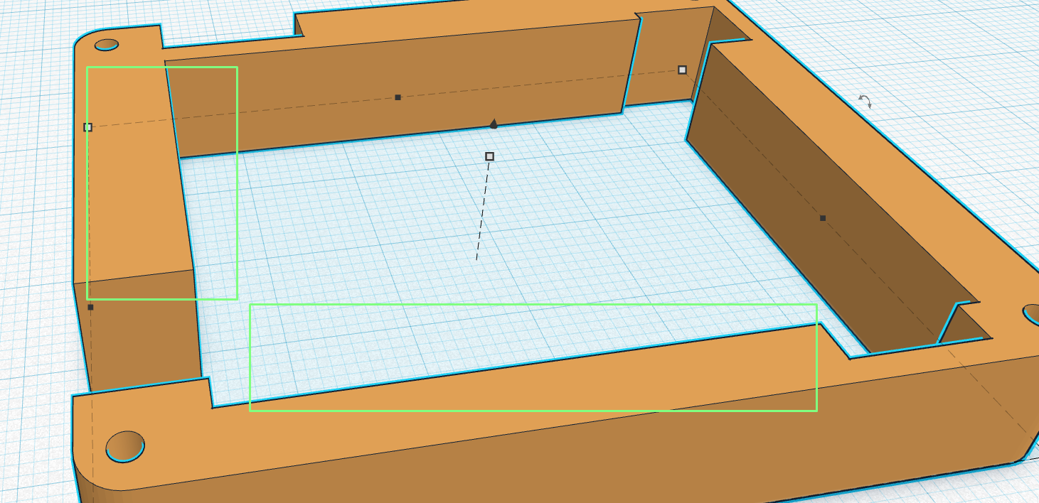
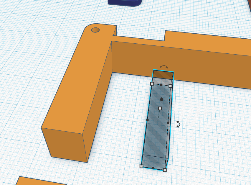
8. Move the oblong so that it becomes part of the left side and use the “cone” on top of the shape to lift it higher. Our goal is to create a “step” in the layer.
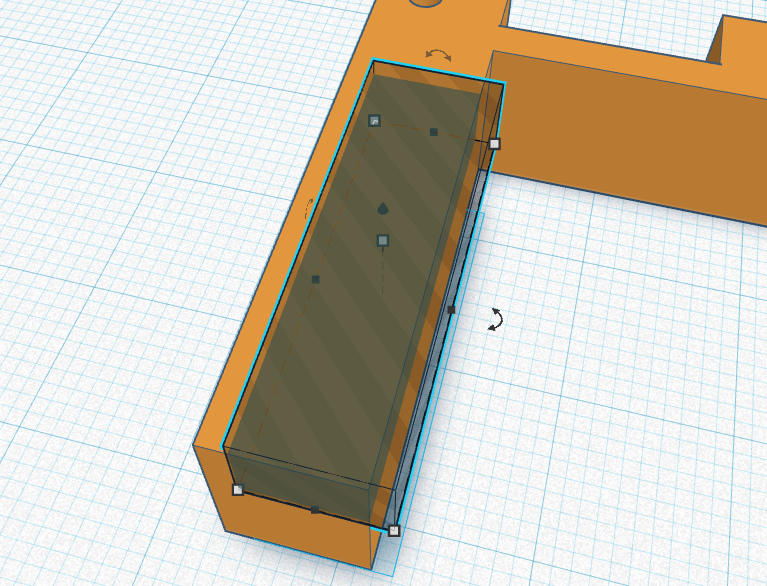
9. Go back to Top view and move the oblong so that it fits neatly. Manually resize the width so that there is no colored block on the right side.You can overhang the hollow oblong as it will never be seen, it is our tool to cut into the model.
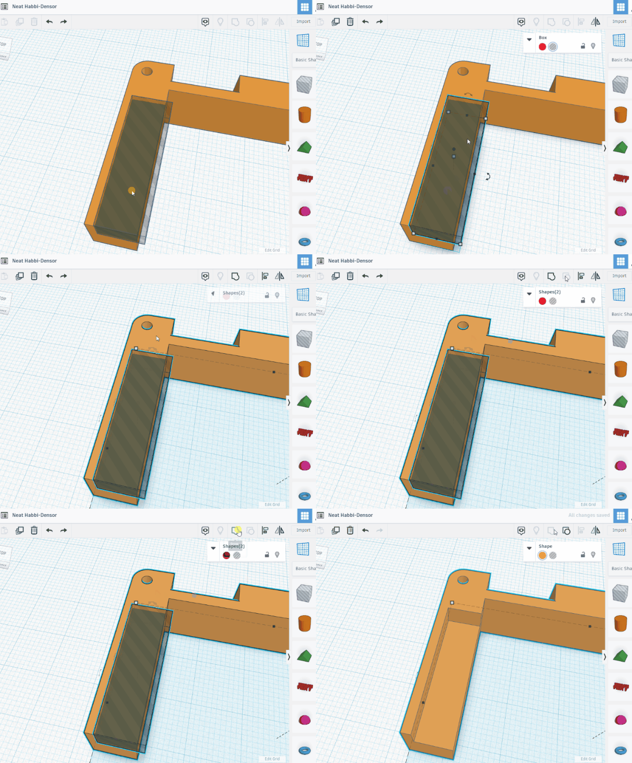
10. Shift, left click on the hollow oblong and the middle layer. Then click on Group to merge the two objects together.
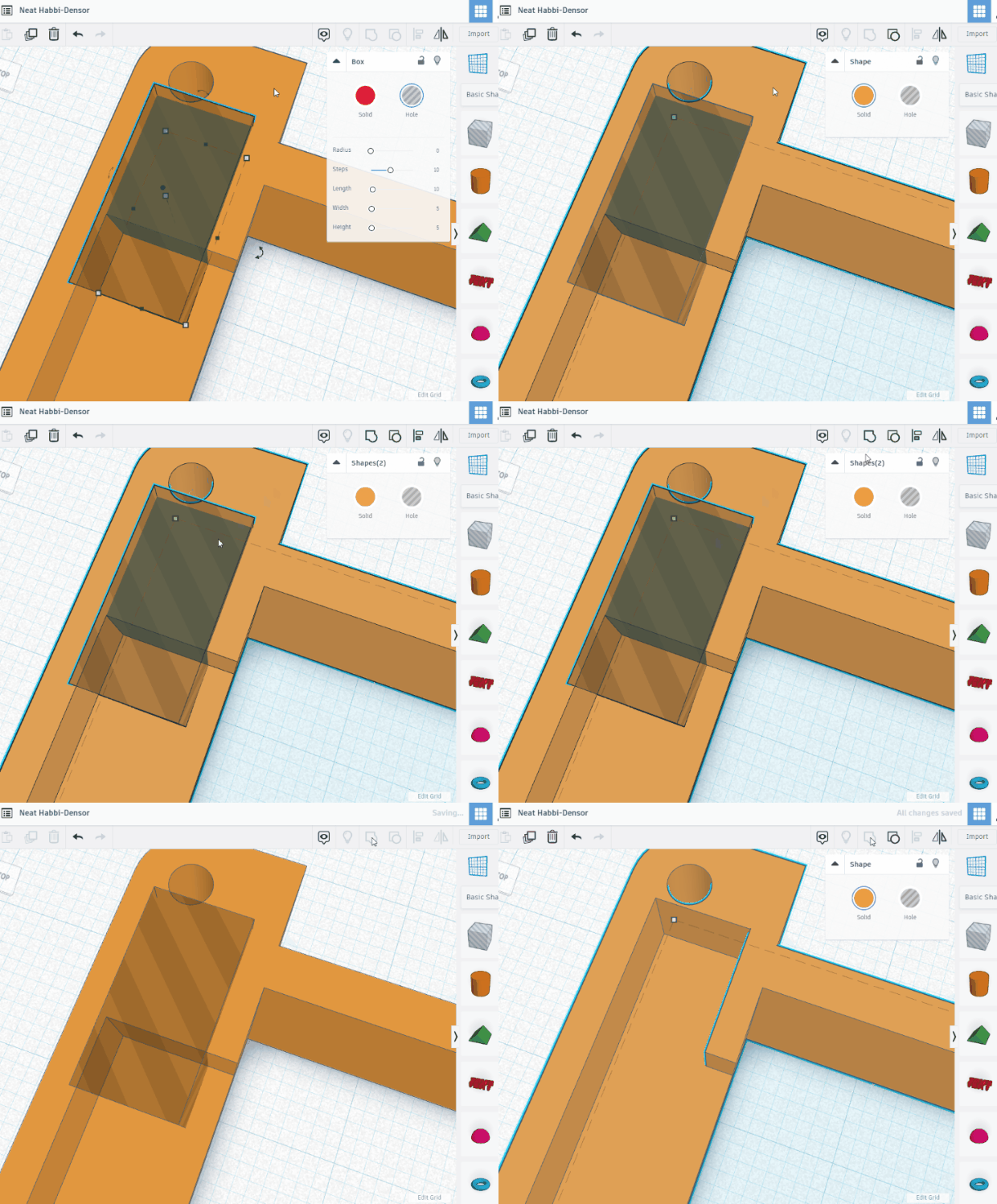
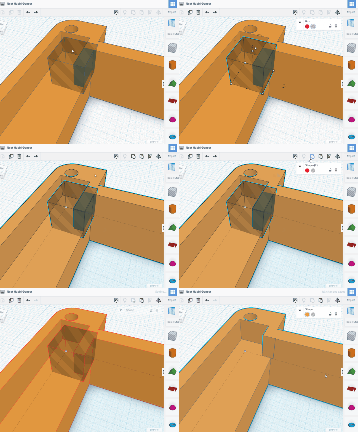
11. Use another hollow oblong to cut a further chunk out of the layer, between the top of the step and the screw hole. A length of 10, width and height of 5mm is ample.
12. Use a 5 x 5 x 5 hollow cube to chop off the remaining section. Group the hollow cube and middle layer then select Group.
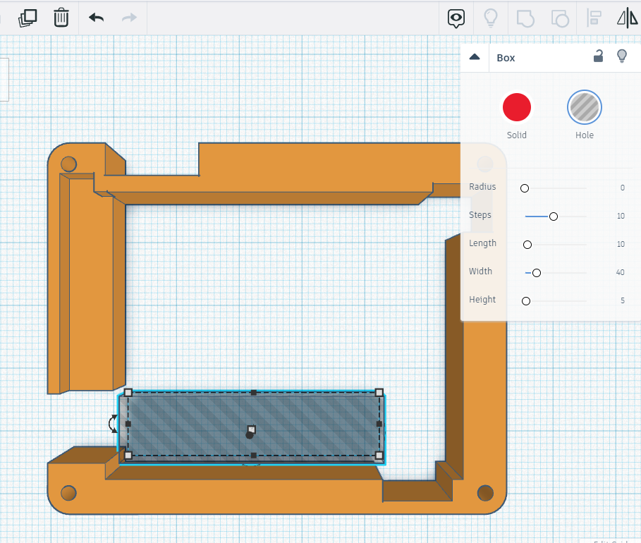
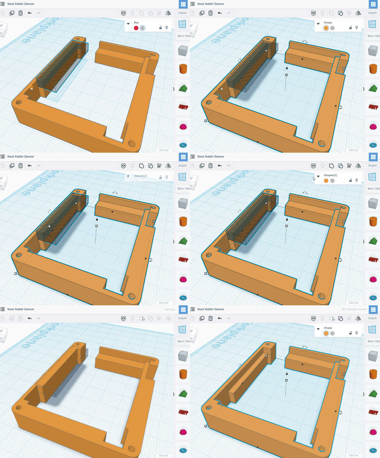
13. Use the same process to cut a chunk from the bottom section. Set the length to 10, width to 40 and height to 5mm.
14. Move the oblong into position and then shift, left click the oblong and layer, then click Group to merge.
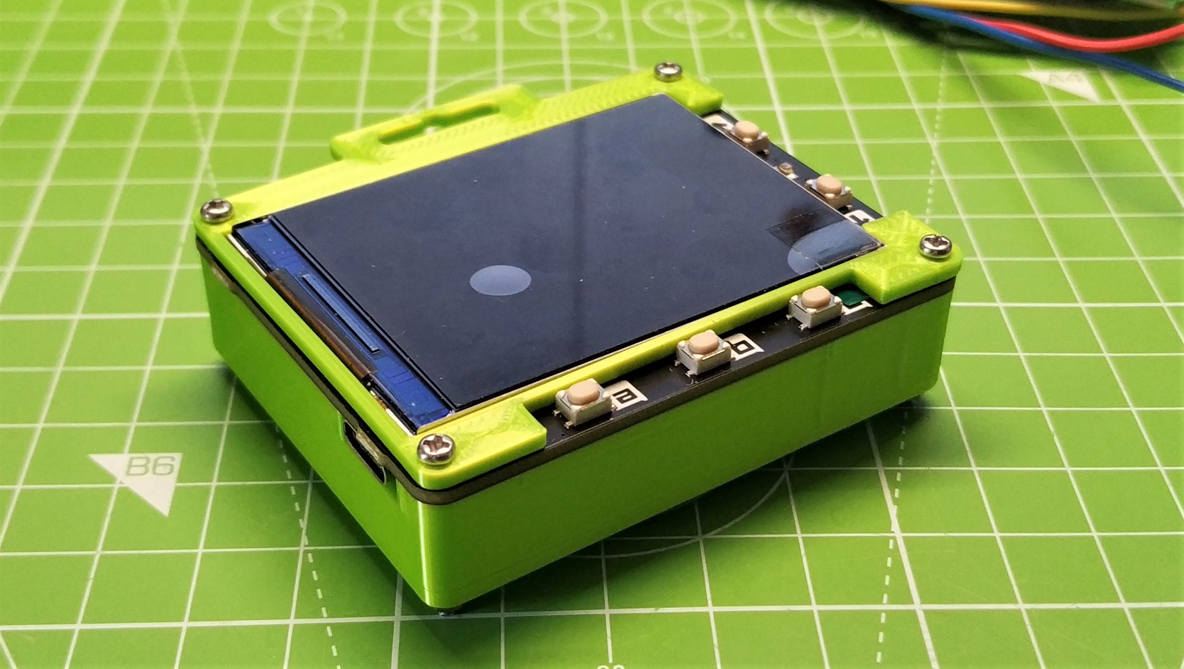
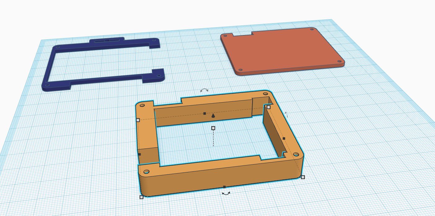
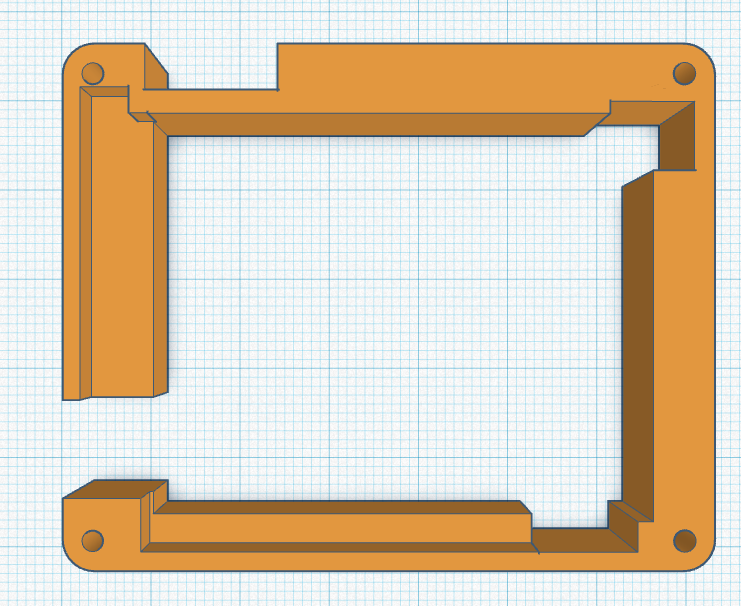
The middle layer should look like this. If not, use undo and try again.
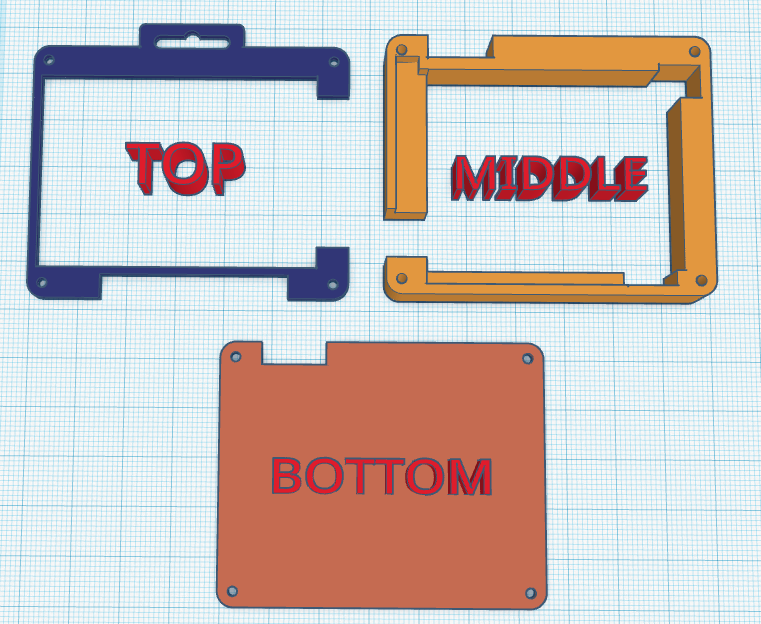
We now have three 3D objects. The top, middle and bottom of a case to enclose a Tufty2040.
Saving and Exporting
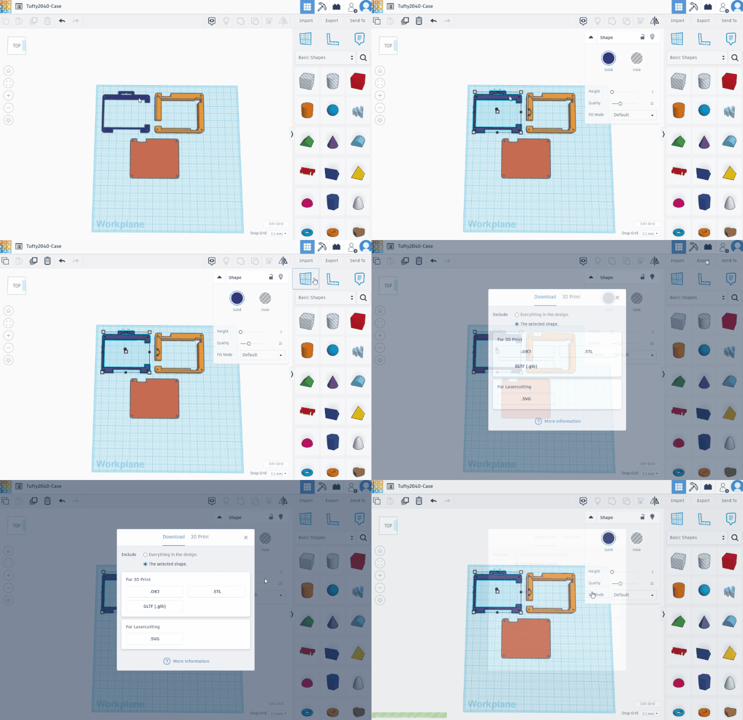
1. Change the name of the project (top left of workspace) to Tufty2040-Case.
2. Select the top layer and then click Export. Select STL and the top layer will download to your computer. Repeat this process for the remaining layers.
Slicing and Printing the Layers
Slicing and Printing the Layers
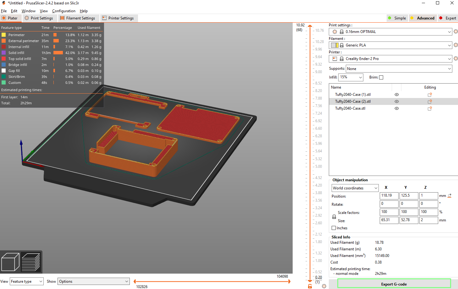
With the STL files downloaded, they can now be sliced using a slicing application such as Cura, PrusaSlicer or OctoPrint. We favor PrusaSlicer as it has a Beta profile for our Creality Ender 2 Pro 3D printer.
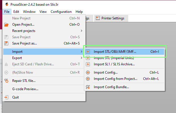
1. Open the PrisaSlicer application and click on File >> Import >> Import STL.
2. Select your project STL files (shift left click) and click Open.
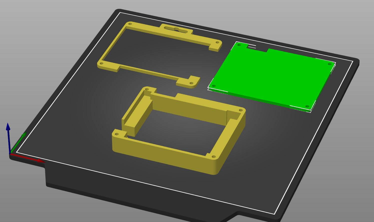
3. Spread the objects on the build plate. Give a little distance between them.
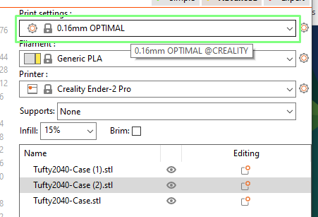
4. From the dialog in the top right, set the print settings to 0.16mm optimal. We later tweaked the settings to create a custom print setting for silk PLA, but this default setting is 90% the same.
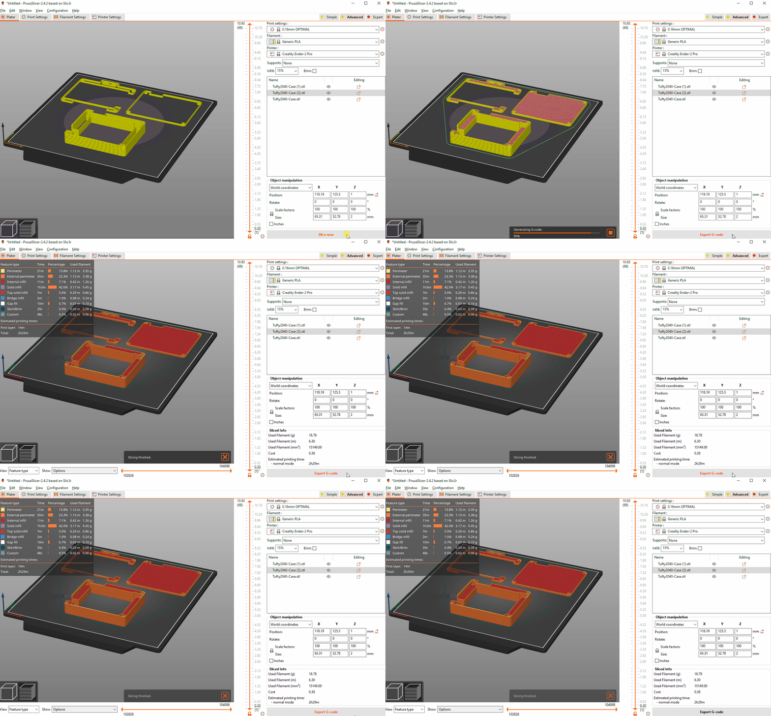
5. Click on Slice Now to slice the print into G-code. G-code is a series of instructions to the 3D printer, it tells the print head where to move to, when to dispense plastic, and when to retract the plastic.
6. Click on Export G-Code and save to an SD card for your printer.
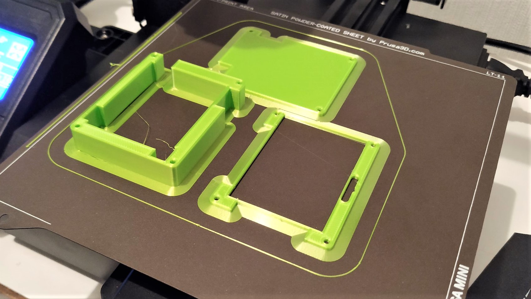
7. Head over to your printer and start the printing process.
Getting there.Quite chuffed that I am 3D printing something that I designed in Inkscape. I think we have a how to in the making @geekinchief pic.twitter.com/KpLIiRaN2eJuly 1, 2022
Building the Enclosure
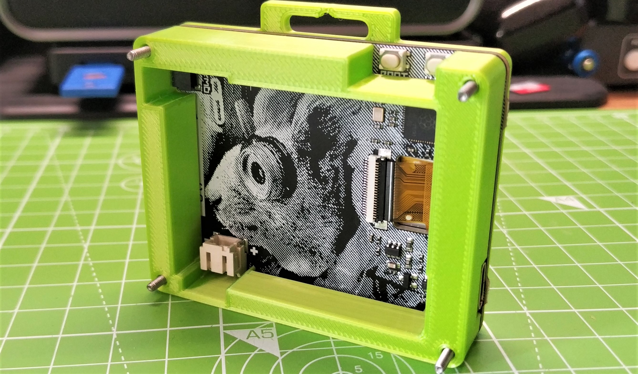
Each of the layers share the same basic footprint, which means that the four M2 18mm machine screws can slide through from front to back. This is a really easy build process.
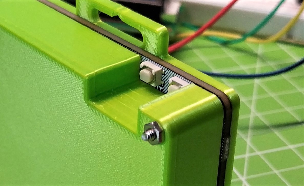
1. Place the top layer on top of Tufty2040 and carefully fit it into place. Take extra care of the button surrounds, these are fragile.
2. Slide the four M2 machine screws through so their heads are proud on the top layer.
3. Slide the thread of the machine screws into the middle layer. Take note of where the USB C cut out is.
4. Slide the thread of the machine screws into the bottom layer. Make sure the cut out for the buttons is correctly orientated.
5. Secure the screw with the M2 nuts.
6. Connect Tufty2040 to your computer and press Power to turn it on.
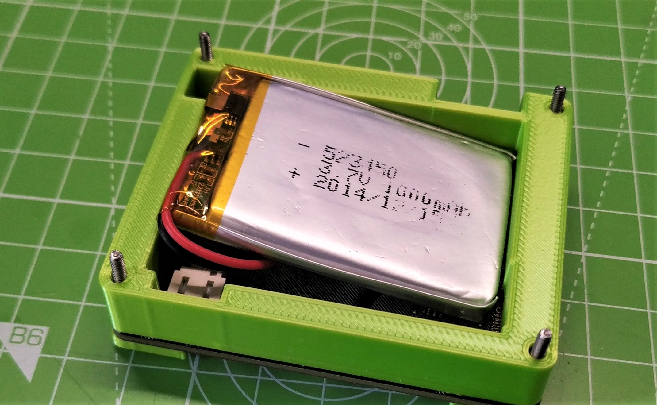
7. After a successful test, remove the USB C lead, remove the bottom panel, insert a charged LiPo battery and carefully put it inside the enclosure. Do not force it!
8. Press the Power button to check that Tufty2040 will run from the battery.
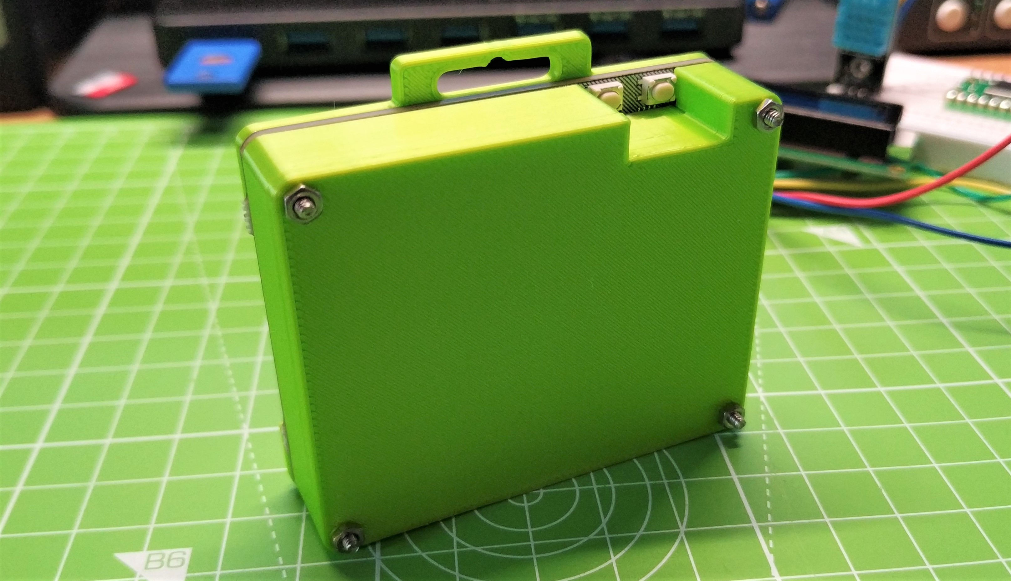
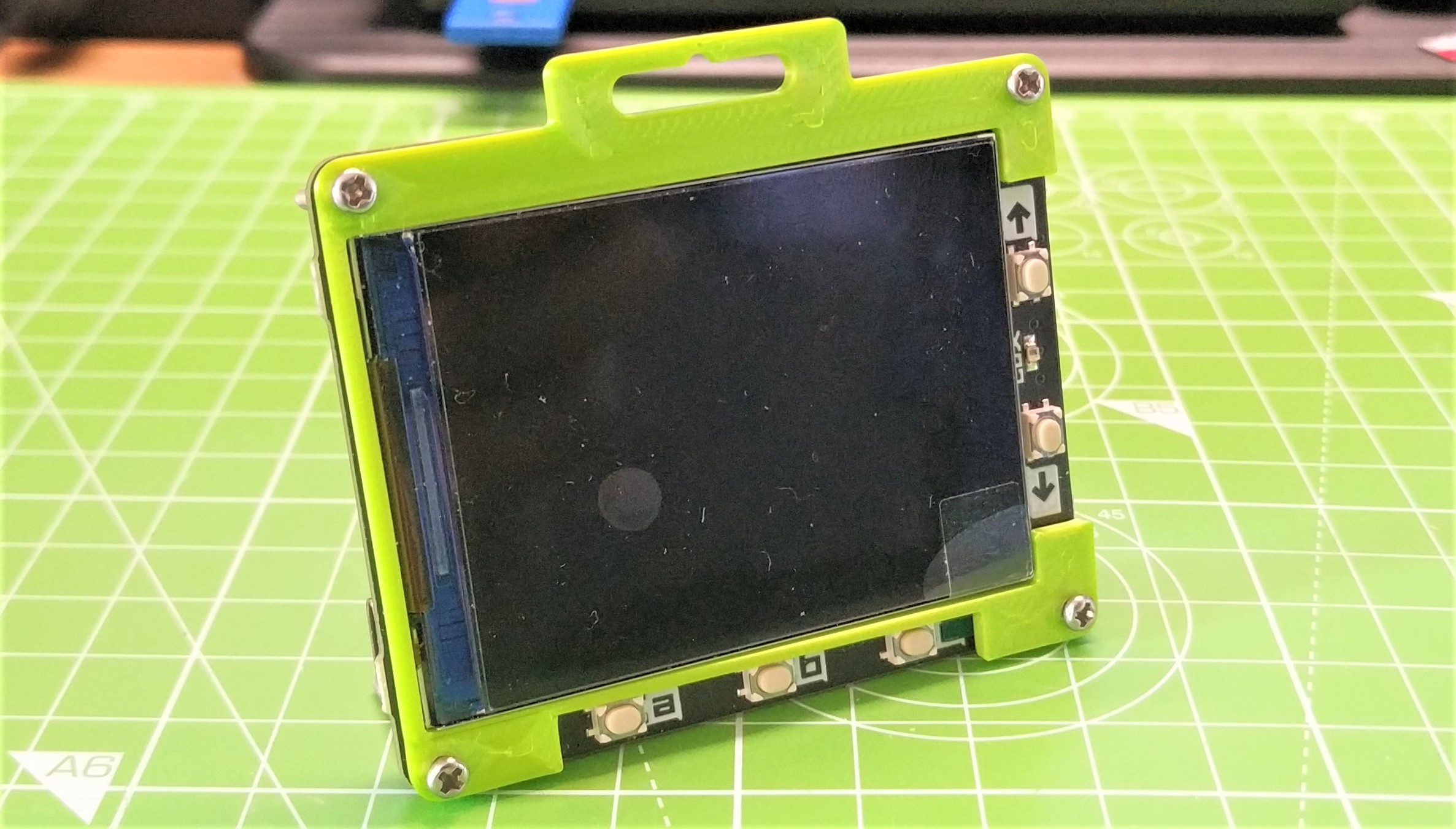
9. Seal up the enclosure and wear your custom 3D printed Tufty2040 conference badge with pride.

Les Pounder is an associate editor at Tom's Hardware. He is a creative technologist and for seven years has created projects to educate and inspire minds both young and old. He has worked with the Raspberry Pi Foundation to write and deliver their teacher training program "Picademy".
-
strobolt Interesting article! As a fledging maker, I'd be interested to hear why you chose to use Inkscape first before importing to Tinkercad?Reply
I'm assuming it must be because Inkscap has better capabilities for that kind of detailed adjustments based on the reference picture.
Is this a good generic approach to first design the different layers (where the cutouts go through the whole depth of the layer) or would it be more or less the same to just go with the Tinkercad straight ahead if your own measurements were all you had to start with? The round edges seem maybe most tricky to implement with Tinkercad (this is coming without being an expert in the software whatsoever).
