SurgeX SA-1810 Tear-Down
Under Pressure
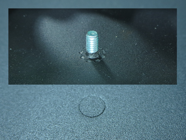
The lone grounding stud in the top cover, as well as all other studs on the bottom, appear to be press-fitted into the sheet metal.
Serving The Tray
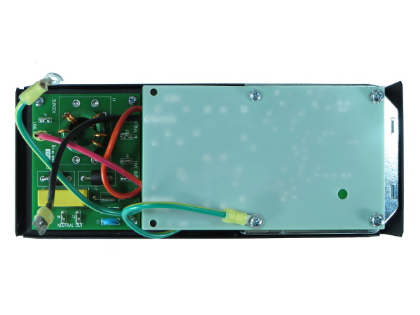
Here we have a top-down look at that bottom tray once all of its other wires are unplugged. Between the filter board, main board and the reactor under it, it looks quite well-packed from this angle too.
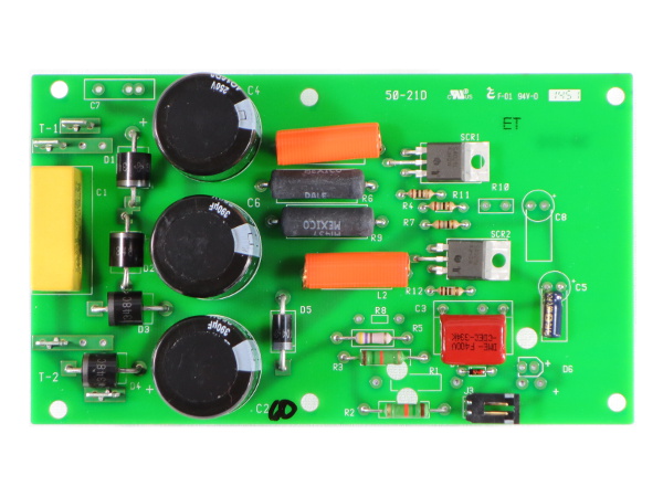
Filter PCB Top
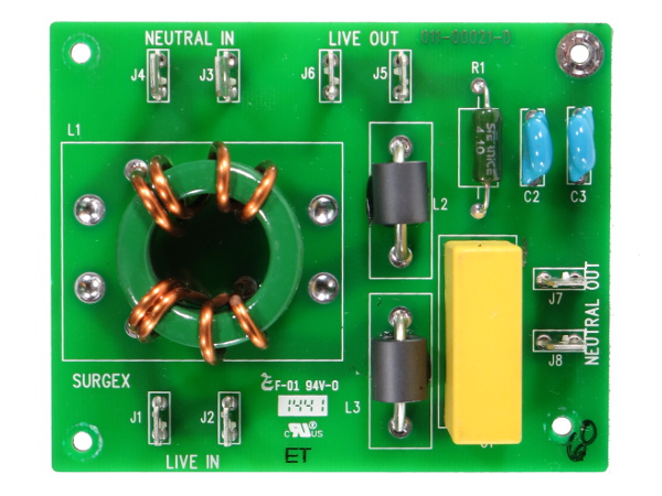
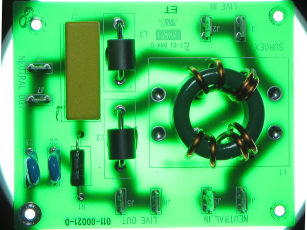
What is the difference between a generic EMI filter and an “impedance-tolerant” one? Simply the addition of small ferrite bead chokes to form a balanced pi (Π) filter with the other X-class capacitor on the main PCB and a 3.3Ω resistor in series with the load-facing 1µF X capacitor to prevent LC resonance. There are also two 2.2nF Y-class capacitors connected from live and neutral to ground through the top-right mounting hole.
With a dual footprint common-mode choke and doubled-up spade terminals everywhere, I believe it is safe to assume this PCB gets reused through much of SurgeX's product lineup.
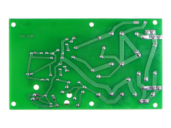
Filter PCB Bottom
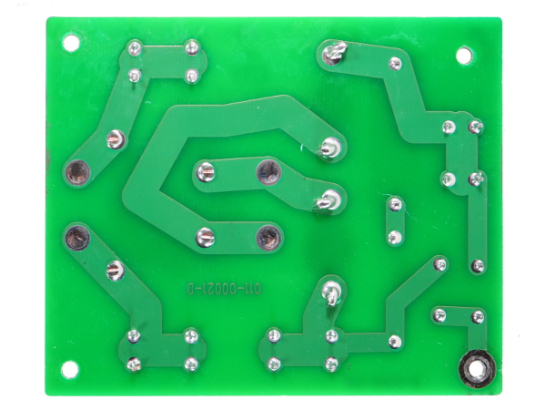
Check out the simple and straightforward PCB routing; not much imagination is required to see how power makes it way from the inputs to the outputs. The fiberglass board is clear enough that you can even see some of the components' outlines through the PCB.
One Nice Thing About Single-Sided Fiberglass PCBs...
...is that you can back-light them to see most of what is happening on both sides at the same time. This isn't particularly useful for such a simple PCB, but it's still a handy trick to keep in mind for more complex circuits.
Ooh, Shiny!
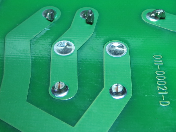
The soldering looks great except for one little detail: achieving mirror-like solder joints requires either a tightly controlled cooling profile for lead-free solder or the cheaper, simpler low-tech option: lead-based solder. I asked Nicholas and was told SurgeX went lead-free for its international products a while ago, but still use 63Pb/37Sn solder for North American models. There's a plan to go lead-free in the works.
Get Tom's Hardware's best news and in-depth reviews, straight to your inbox.
PCB And Reactor Sandwich
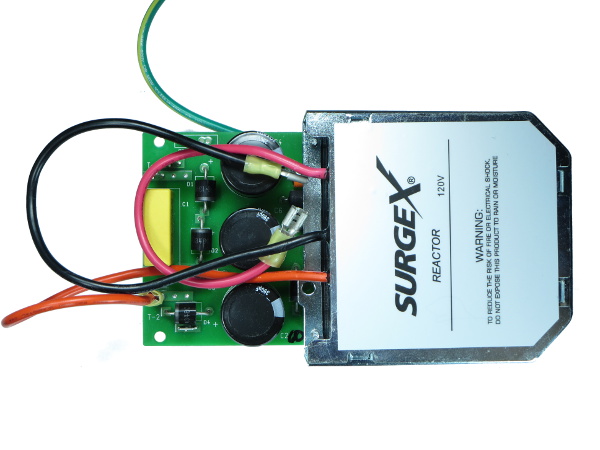
The heart and soul of SurgeX's ASM protection is a huge inductor with complementary electronics to take care whatever remaining power surge energy manages to pass through it. High-performance and -endurance surge protection adds a fair amount of complexity compared to basic MOV protection.
In Perspective
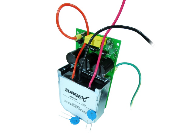
How much bigger than conventional MOV protection do you need to go if you want a high-endurance surge protection solution? Well, here is the reactor with its PCB next to a pair of Bourns 20D201K MOVs for comparison. The size and weight differences are not subtle.
Main PCB Top
How much electronics do you need to do a MOV's job when you do not wish to use a sacrificial element? About this much. And the circuitry is only intended to deal with the remainder of surge energy that manages to pass through SurgeX's reactor.
From left to right, we have an AceWin 1µF X2 cap, a discrete bridge made of Vishay P600G diodes, three 390µF 250V Panasonic ED capacitors, a Vishay 1N5404 diode for the peak detection circuitry, a pair of power resistors to discharge the surge suppression caps, air-core inductors to limit current rise rate through the SCRs and the LittleFuse S4025 SCRs with their trigger components.
Main PCB Bottom
The soldering quality looks similar to the filter board. Most modern PCB designers would use copper pours with thermal relief pad connections and 45/90° trace routing. Here, though, SurgeX's PCB engineer decided to forgo copper pours and also use free-hand routing.
-
Evil_Overlord Thank you for this write-up. In my eyes, this article is a shining example of what (technical) journalism should be. It is both worthy of being used as a product review, and reference guide. If I were going shopping for a series-mode surge suppressor, or if I knew someone who was shopping for a power protection solution for power-sensitive equipment, I would -without pause- recommend using this article as a launching pad for any/all research.Reply
Two things in this article stand out and gave me a reason to write this comment. First: You didn't give up. When faced with equipment that could not perform all the tests you desired, you switched to a simulated circuit. That takes time, research, and effort. Second: You openly admitted the transition from real-world to simulation. Lesser authors might skipped that disclaimer.
Well done. -
mortsmi7 They go to all the trouble of making such a beefy product and then they back-stab the outlets. The cross-section of a stab connection is very low compared to a screw-type. A space heater, which applies a constant high amperage, will kill a back-stabbed outlet in no time.Reply -
Daniel Sauvageau Reply
They make models for just about every country, you just need to go through surgexinternational.com to pick your country. All they need to do is put the appropriate cord and transformer/reactor in, increase the bleeder resistors' value for 220-240V countries and that's probably it*.16422851 said:Interesting , do they have a European version of this ?
Edit: *and put 400-450V electrolytic input caps in instead of 250V since 240V crests near 350V.
Thanks.16423853 said:Thank you for this write-up.
Two things in this article stand out and gave me a reason to write this comment. First: You didn't give up. When faced with equipment that could not perform all the tests you desired, you switched to a simulated circuit. That takes time, research, and effort. Second: You openly admitted the transition from real-world to simulation. Lesser authors might skipped that disclaimer.
Well done.
I had already done a fair chunk of the simulation research almost a year ago after getting into an argument with some readers about SurgeX and similar products, so I was basically biting my time to do something with the results and what I learned during that process.
As for admitting to using simulated results, this simply requires a lot less effort than producing convincing fake results. The main reason I do it though is as a shout-out to test equipment manufacturers: "if you had sponsored me with test equipment relevant to this story, your gear would have probably been shown or at least mentioned here." -
Daniel Sauvageau Reply
These are not "stab" connection with the crappy leaf-springs snaring wires. They are captive nut connections: the wire gets secured between the captive nut (a piece of cast metal with a tapped hole the terminal screw screws into and grooves to guide the solid copper wires) and screw/terminal by tightening the screw.16424079 said:The cross-section of a stab connection is very low compared to a screw-type. A space heater, which applies a constant high amperage, will kill a back-stabbed outlet in no time.
As far as current-passing capacity, those captive slab types should be every bit as good as plain screw terminals: they are basically the same except that instead of the wire being squeezed directly between the screw and outlet metal strip where you need to wrap the wire around the screw just so it does not slip out from under the screw while tightening, the wire is squeezed between the captive slug and the metal strip with the groove guiding the wire in place, eliminating the need to wrap the wire around the screw. These same grooves might actually provide more total contact area with the wire than the screw head does. -
blackmagnum Thanks Daniel for the tips. When using $1k plus computer equipment at work or home, it has been proven that you should play safe with reputable power delivery than be cheap and sorry.Reply
