SurgeX SA-1810 Tear-Down
I See Through
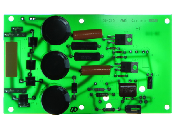
If you follow the self-test LED header traces near the bottom-right corner, you find out that it is simply a LED connected directly across the main input capacitor through a pair of series 15kΩ resistors – a glorified “Power On” indicator that doubles as the bleeder circuit for the main surge filtering capacitor.
Following traces around non-populated components reveals that they are alternate footprints, component orientations or alternate signal path implementations, no mysterious missing feature there.
Location, Location, Location
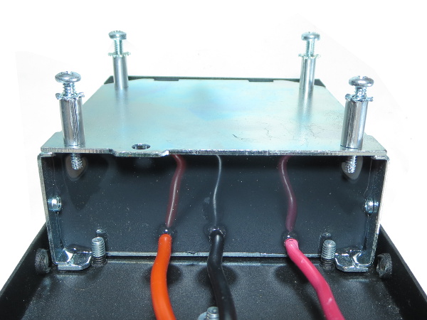
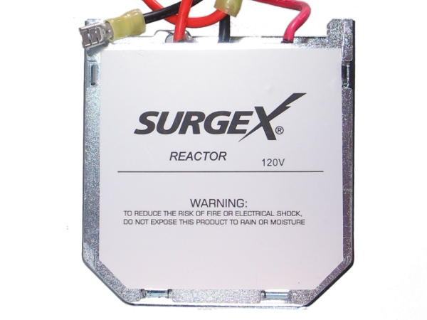
Do you see those two studs just below the reactor's steel casing? These help keep the bulky device from shifting around. I am a little surprised to see no nuts on them, which would properly secure such a large component. But the way they butt right up against the putty tells me they were intentionally left nut-less.
Hanging By Two Threads
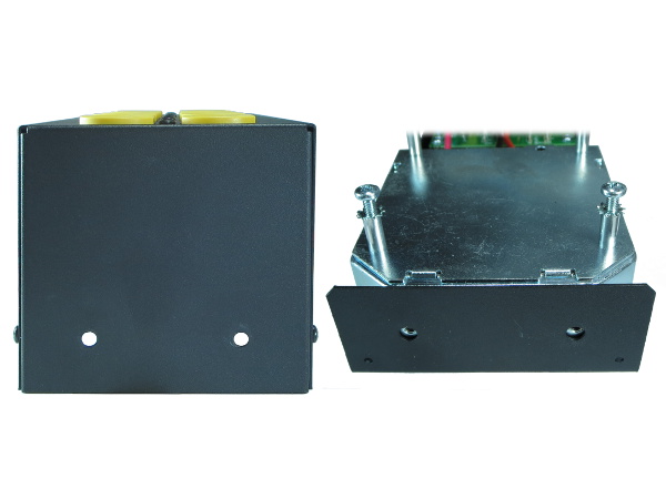
This is my only major bit of criticism about the SA-1810's mechanical design: since there are no nuts on the locator studs, all of the reactor and main PCB's weight is held in check by two metal screws through the side panel, meaning a hard upside-down landing could warp the side panel (although improbable with the combined thickness of the overlapping walls),snap the screws or strip threads in the reactor's housing. The main PCB riding on the reactor might not appreciate getting whipped around in such way, either.
How Big Is Big?
We know this device is physically large (10x10x4 centimeters or 4x4x1.6 inches for those of you who want to know how chunky it is). But how much inductance does it actually provide? By measuring impedance against a 1Ω resistor, I calculated a primary inductance varying from 132µH at 60Hz down to 3.7µH at 20kHz. When you want a high value non magnetically saturatable inductor capable of passing 20ARMS and ~1000A peak primary current, you pay the price in volume, weight and copper.
On an unrelated note, how often do you see “do not expose to rain” on internal components? I believe this is a first for me.
1/20,000th Of A League Under The Putty
Since the transformer is potted in epoxy or some other tough material to prevent vibrations, help with heat transfer, increase the working voltage and various other reasons, I tried asking for pre-potting pictures. Unfortunately, they were deemed too sensitive for release.
Get Tom's Hardware's best news and in-depth reviews, straight to your inbox.
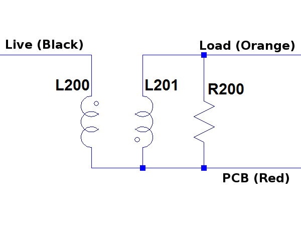
Basically, what you have in there is a pair of loosely coupled copper coils and some low value shunt resistor attached to the secondary winding. Based on US patent 7068487, reactor parameters for a 120V/15A reactor should be 80µH primary inductance, 4µH secondary inductance, a 0.35-0.65 coupling factor between the two windings and a shunt between 0.01 to 0.2 ohm.
The idea here is that when a surge gets presented on the primary, a proportional and opposite voltage appears on the secondary winding, canceling out the residual surge seen by the load relative to the intermediate tap.
Empty Tray
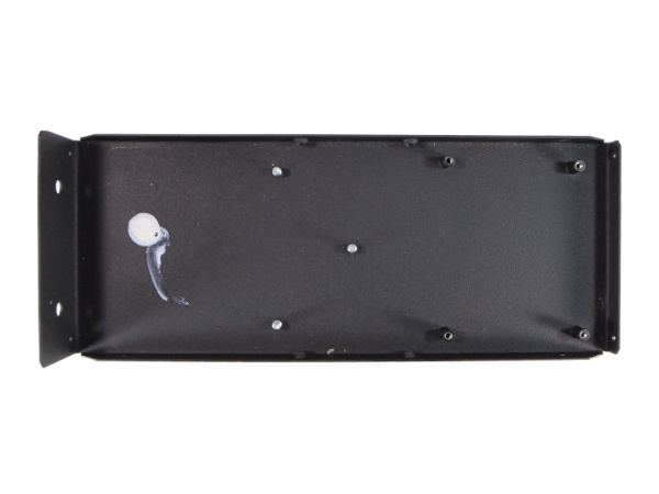
With everything removed, we are left with the bottom tray that features four threaded spacers for the filter PCB, one threaded stud for grounding, two more studs to locate the reactor and a glob of RTV presumably intended to keep the reactor from rattling around during shipping.
If the adhesive was intended to secure the reactor on the tray, then it failed in transit since there was no resistance when I lifted it out. The sticker does not show any sign of ever have been in contact with anything, hinting that the RTV may have cured before the reactor ever got dropped in. When I sent a draft copy of this story to Robert for review, he told me the RTV blob should have been bigger and definitely not have come loose on its own.
Circuit Operation
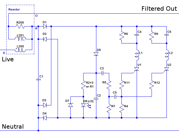
How does it work? Here is a schematic I put together for simulation purposes.
Under normal operating conditions, AC voltage goes through the rectifier bridge, through D5, top off C2 to AC peak voltage and that is it. The low shunt value (R200) reflected through the L200/L201 transformer effectively shorts it out.
When a surge occurs, L200's inductance opposes any sudden change in current. Part of the surge voltage across L200 appears across L201 to cancel most of the initial spike. Some surge energy gets dumped in C2 causing it to rise a few volts and the sharp rise triggers the SCRs. With C4 and C6 initially discharged, the center leg gets shunted to neutral, diverting the remaining surge energy let-through to C4/C6 and the L201-R200 loop.
When the surge is over, R6 and R9 discharge their respective caps and R200 dissipates the remainder of the energy stored in L201's field.
Take It Apart, Then Turn It On
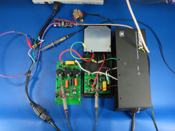
How does all that translate into actual operation? Time to rig things for poking around. Some of you may have noticed that ground clips are missing from my probes. With this much exposed 117VAC on my bench, they are not worth the risk of accidental shorts.
What is the device at the end of that coax cable you might ask? It is a simple differential probe based on the AD629 amplifier that I use for shunt current measurements. It used to reside on a breadboard until a month ago, when I received the PCB I designed for it.
What Does The Scope Say About Its Power Levels?
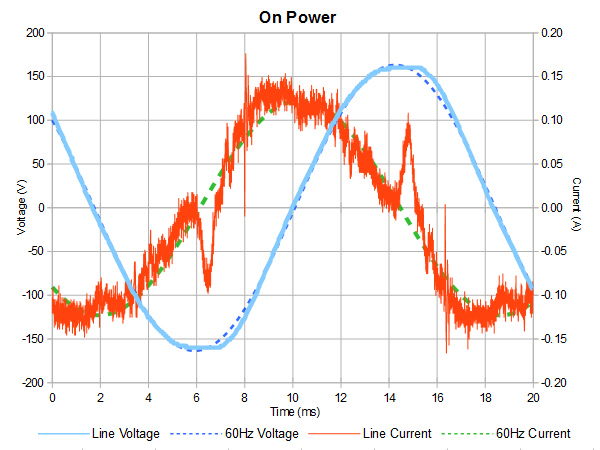
With nothing plugged in, I measured an integral power of 837mW, which is basically the power being dissipated by the self-test” LED and its 30kΩ bleeder/limiter resistor. Apparent power, the product of RMS voltage and current, is 10.6VA.
The bulk of this 10VA is simply the fundamental current going back and forth through the reactor and X capacitors. Smaller bumps near AC peaks are the peak detection capacitor getting topped off to restore the charge bled off by the LED. As for the narrow glitches on the current waveform, they might be caused by the diodes' reverse recovery.
Let's Get Unscientific
When I first read about SurgeX, I spontaneously asked myself two questions:
- How well does it actually work?
- What happens with that large inductor if a horribly noisy load is connected to the unit?
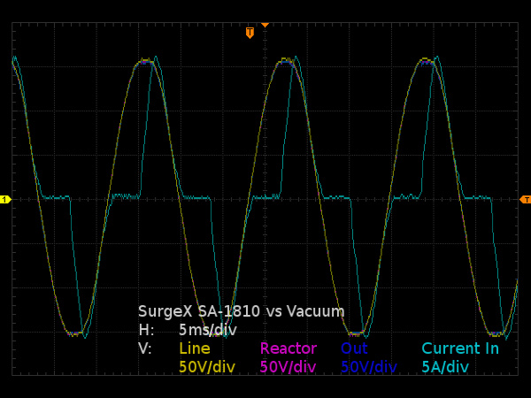
I do not currently have the necessary equipment to answer the first question. But for the second one, I can use the vacuum cleaner test from my isobar Tear-Down – SCR/triac variable speed drives are fairly good AC noise sources.
My probes were connected to the three reactor legs (input, main board and output) to see if there would be any dips or ringing around turn-on time. The three voltage traces overlap almost perfectly with no apparent oddities, so no problem here even with this unusual load.
-
Evil_Overlord Thank you for this write-up. In my eyes, this article is a shining example of what (technical) journalism should be. It is both worthy of being used as a product review, and reference guide. If I were going shopping for a series-mode surge suppressor, or if I knew someone who was shopping for a power protection solution for power-sensitive equipment, I would -without pause- recommend using this article as a launching pad for any/all research.Reply
Two things in this article stand out and gave me a reason to write this comment. First: You didn't give up. When faced with equipment that could not perform all the tests you desired, you switched to a simulated circuit. That takes time, research, and effort. Second: You openly admitted the transition from real-world to simulation. Lesser authors might skipped that disclaimer.
Well done. -
mortsmi7 They go to all the trouble of making such a beefy product and then they back-stab the outlets. The cross-section of a stab connection is very low compared to a screw-type. A space heater, which applies a constant high amperage, will kill a back-stabbed outlet in no time.Reply -
Daniel Sauvageau Reply
They make models for just about every country, you just need to go through surgexinternational.com to pick your country. All they need to do is put the appropriate cord and transformer/reactor in, increase the bleeder resistors' value for 220-240V countries and that's probably it*.16422851 said:Interesting , do they have a European version of this ?
Edit: *and put 400-450V electrolytic input caps in instead of 250V since 240V crests near 350V.
Thanks.16423853 said:Thank you for this write-up.
Two things in this article stand out and gave me a reason to write this comment. First: You didn't give up. When faced with equipment that could not perform all the tests you desired, you switched to a simulated circuit. That takes time, research, and effort. Second: You openly admitted the transition from real-world to simulation. Lesser authors might skipped that disclaimer.
Well done.
I had already done a fair chunk of the simulation research almost a year ago after getting into an argument with some readers about SurgeX and similar products, so I was basically biting my time to do something with the results and what I learned during that process.
As for admitting to using simulated results, this simply requires a lot less effort than producing convincing fake results. The main reason I do it though is as a shout-out to test equipment manufacturers: "if you had sponsored me with test equipment relevant to this story, your gear would have probably been shown or at least mentioned here." -
Daniel Sauvageau Reply
These are not "stab" connection with the crappy leaf-springs snaring wires. They are captive nut connections: the wire gets secured between the captive nut (a piece of cast metal with a tapped hole the terminal screw screws into and grooves to guide the solid copper wires) and screw/terminal by tightening the screw.16424079 said:The cross-section of a stab connection is very low compared to a screw-type. A space heater, which applies a constant high amperage, will kill a back-stabbed outlet in no time.
As far as current-passing capacity, those captive slab types should be every bit as good as plain screw terminals: they are basically the same except that instead of the wire being squeezed directly between the screw and outlet metal strip where you need to wrap the wire around the screw just so it does not slip out from under the screw while tightening, the wire is squeezed between the captive slug and the metal strip with the groove guiding the wire in place, eliminating the need to wrap the wire around the screw. These same grooves might actually provide more total contact area with the wire than the screw head does. -
blackmagnum Thanks Daniel for the tips. When using $1k plus computer equipment at work or home, it has been proven that you should play safe with reputable power delivery than be cheap and sorry.Reply
