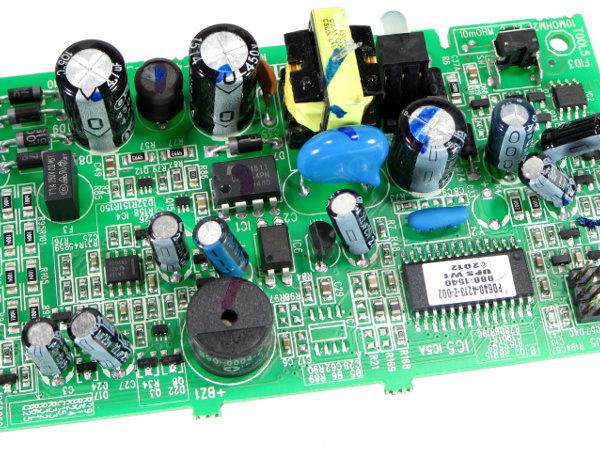
APC BE550G Tear-Down
Jelly Beans
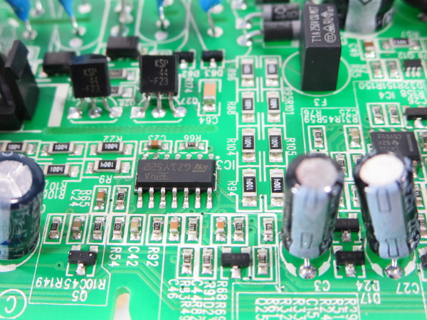
There's nothing too fancy in the analog processing department. All of the sensing and filtering is covered by a 324A chip (quadruple general-purpose operational amplifier), an LM358 (a slightly worse single general-purpose op-amp) and a handful of passives for voltage dividers and signal filtering.
The Three Stooges
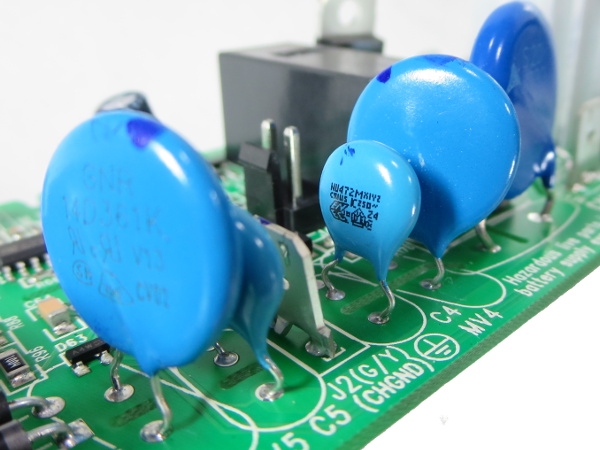
As is common in better entry-level surge protectors, you get a pair of smaller, higher-voltage MOVs between ground and live/neutral, and a beefier lower-voltage MOV across live and neutral. The primary MOV is an Epcos S20K230, while the other two are GNR 14D361Ks. Although it's not visible here, there is an X-class filter capacitor hidden behind the Epcos MOV.
Redundant Reminding
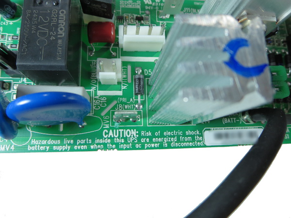
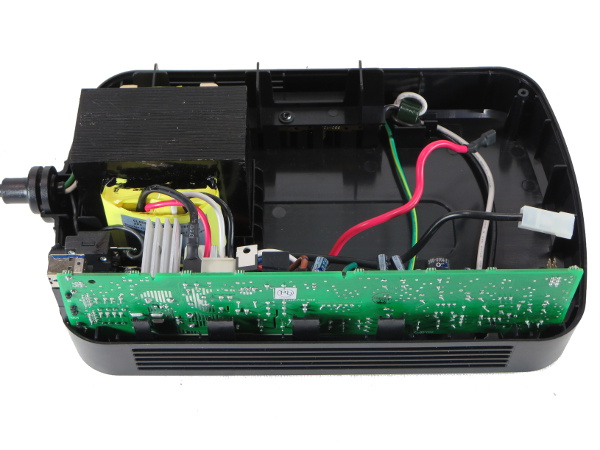
You're reminded of the possible presence of high voltage on your way in after pulling the battery out of its compartment. There's another reminder after pulling the PCB out from the enclosure. As before, the battery was disconnected long before you get to this point.
By the way, you can see that hidden gray X-class cap behind the MOV. You can also see a sample of those labeled connectors complete with function and wire color (always handy for re-assembly).
Simple Quality Control
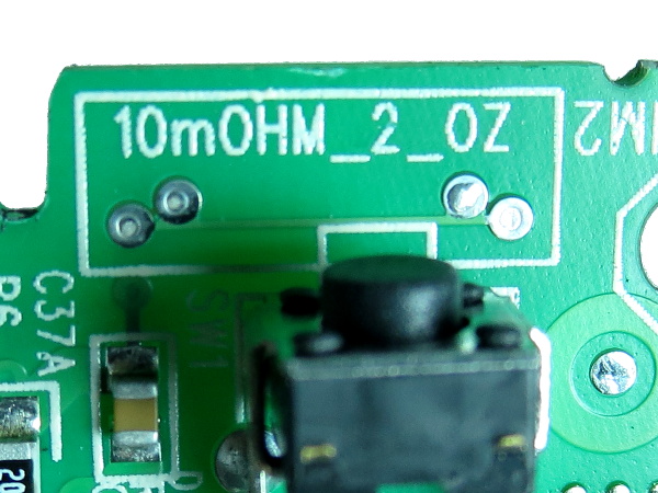
A simple way to avoid boards getting etched with the wrong copper thickness or getting over-etched is to use one or more test tracks. The four pads are for what is called a Kelvin four-terminal resistance measurement. A known current is applied across the track using the end pads and the voltage across the test length is measured using the other two to accurately determine resistance. This eliminates the measurement error introduced by test leads when measuring very small resistances. Here, the markings tell us that if the board got etched correctly out of a PCB with two ounces of copper per square foot, the test track should measure 10mΩ.
There is another similar test track near the opposite board corner to check for etch and copper uniformity.
More Squiggles
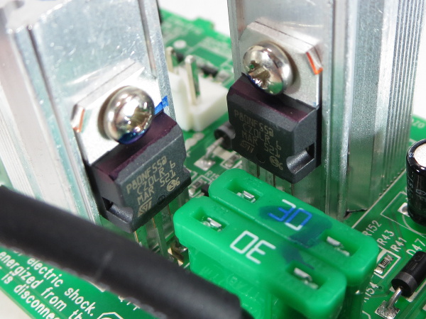
A pair of ST80NF55 FETs handle switching the inverter’s primary winding. Someone was clearly tasked with checking that those heat sink screws went in, with blue marker squiggles as proof, in addition to a few other components like the pair of 30A fuses in the bottom-right corner. If you did not already guess it from the part numbers, those N-channel FETs are rated for switching up to 80A and 55V.
Get Tom's Hardware's best news and in-depth reviews, straight to your inbox.
Standby Power
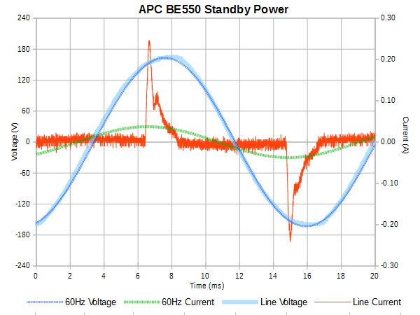
How much power does the BE550G consume while plugged in? The answer is 48mARMS at 116V or 5.6VA with a power factor of 50%, which means only 2.8W of actual power dissipation. By feel, I can barely tell that the BE550G is above room temperature. This is much more reasonable than the SMART1000’s 12.4W and 40-45 °C chassis temperature.
BE550G vs. SL300
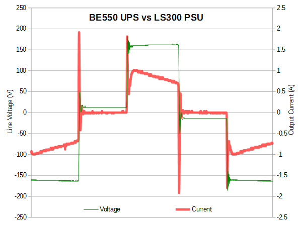
This looks a fair bit different from the LX and SMART: the BE550’s inverter output only goes to 160V instead of the other two’s 180V. Because of that, it needs a higher duty cycle (roughly 50%) to provide 118VRMS. The combination of higher duty cycle leaving input capacitors less time to discharge into the load (my 80W LED strip) and lower inverter output voltage also reduces its current peaks from 3.5A to 2A.
Out of curiosity, I plugged the output waveform data into my power analysis spreadsheet and calculated the THD of this voltage waveform to be only 41%, 4% better than stated on the label.
Shaving Pennies
After seeing how many corners Tripp-Lite cut in the SMART1000, I was curious to find out if the much cheaper APC BE550G would fare better. For half the price, you get a slightly worse battery (7Ah vs. 8Ah), 77% lower standby power consumption, no built-in display and no AVR function, even though the transformer has the necessary extra winding and connectors for every wire except the battery’s negative terminal. It looks like APC doesn't shave as many pennies from its entry-level products as Tripp-Lite does from its mid-range designs.
Expectations Met?
I did find three flaws in the unit’s design: the seemingly incorrect location of the first common-mode choke, the use of a #18 jumper wire for the PCB and battery backup outlets’ ground, and, most important, the use of those unreliable flap strips for the ground contacts. Thankfully, none of the equipment I plan to connect to this UPS has ground connections, and I have no plan to use the surge-only outlets either. As a result, all three complaints become non-issues for my application. The use of second- and third-tier capacitor brands may also be a point of contention. Since the unit is covered by a three years warranty, I would expect the capacitor selection to be reasonably conservative.
Apart from my disappointment with the ground strips, the BE550G appears to be a fine little UPS.
MORE: Tripp-Lite SMART1000LCD Tear-Down
MORE: CyberPower LX1500GU-FC UPS Tear-Down
MORE: SurgeX SA-1810 Tear-Down
-
nukemaster Going to be interesting what you find in that RS/XS/BX(looks like them)?. Older units may have the same idle power draw issues you saw on the Tripp-lite unit.Reply
Thanks for posting this. -
Daniel Sauvageau I didn't have the necessary equipment to make waveform measurements at the time but you can find the BX1000's tear-down over here: http://www.tomshardware.com/picturestory/666-ups-battery-backup-tear-down.htmlReply
It is a completely different critter, using a DC-DC step-up converter and an output bridge instead of a transformer. The old BX's iron core transformer is used exclusively for the AVR function.
I would make input power measurements if I could but the reason I got started on this streak of UPS tear-downs is because my ~10 years old BX1000 died late last year: whenever I turn it on, it clicks for several seconds and then goes to battery power. Until I get around to fixing that, whatever measurements I make may be completely bogus. I'll probably end up writing a repair story about it when I get there. I have already had a quick look inside but the obvious suspects turned out to be dead ends.
Edit: I went to measure the BX1000's standby power while 'off' (the battery charger is still active in that state) and it draws 3.8W. I would not expect the normal 'on' power to be much over 1W above that since the only "power-hungry" thing that distinguishes the 'off' and 'on' states is operating the bypass relay. -
nukemaster I almost forgot you opened that unit. I wonder how close to my old XS1200 it is. Mine is warm on the side so I always guessed it was just a power waster.Reply
I also have a very old SmartUPS 1400(got it for free and just had to add the batteries) that runs warm enough(10 - 11 degrees above room temp if I trust its software). Cools down allot when the fan kicks in(run or charge).
Again, thanks for taking the time to take these things apart.
-
Daniel Sauvageau It does not take much power to get things slightly warm when there is only natural convection moving heat around and limited venting directly above the heat source to let that heat out.Reply -
Memhorder Thanks again Dan. Hey have you ever done the software side of things? I know it doesn't apply to this unit but say the Cyber Power you were hinting. I've noticed that using Cyber Power panel is just not accurate when trying to figure load in real time. The bar just doesn't move when you know the computer is sucking more juice under heavy use.Reply -
Daniel Sauvageau Reply
I haven't used PowerChute or any other manufacturer software in years. I simply set Windows' power and battery management settings to bypass third-party software. If I want to read the UPS' stats, basic parameters like battery state of charge, input voltage and output power are usually readable by HWInfo and other System Management Bus (SMB) monitoring tools.18149137 said:Hey have you ever done the software side of things?
-
alextheblue Glad to see APC doesn't skimp too much even on a low-end unit. One might perhaps mitigate the ground pin issue with a few "outlet saver" mini-extensions.Reply -
Onus I just don't like those output waveforms. Ok for light bulbs I suppose, they look ugly for electronics.Reply
Nice to see this one apparently got a thorough QC treatment.
-
photonboy Don't forget to ensure a UPS is compatible with the power supply. Many need a "pure sinewave" to support Active PFC (which is required for an 80-plus rating).Reply
Cyberpower has models with "PFC" right in the name to help avoid confusion. -
nukemaster I would say as long as you keep it away from some electric motors and other devices that just do not work properly on this waveform, It should not be an issue. It is not like most users run this way long term or anything.Reply
All of my computers have run ok on stepped wave so far(but the SmartUPS is sine). I know some active power factor power supplies(but not all) may not get along with this waveform however.
