APC BE550G Tear-Down
Outlet Strips
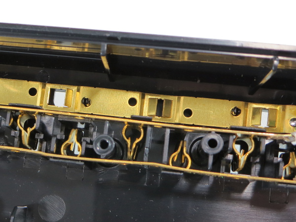
What lies under those outlet strip covers? The nice round stamped metal pinchy fingers for the neutral and live strips, and the lousy stamped flaps for the ground connections. Insert a ground pin a few times into these and the flaps spread apart in a mostly plastic (permanent) deformation. Eventually you get intermittent or no contact from those. I would not plug any equipment with safety-critical ground into an UPS or power strip using this type of ground strip.
Naughty APC
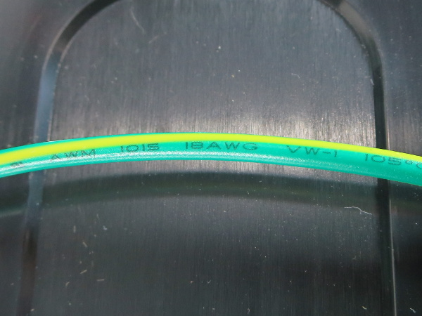
Ground wires should be the same gauge as the feed wires to make reasonably certain they can safely carry whatever fault current the feed wires provide. Here, the cord is 3x16, but the ground wire linking the surge-only strip to the PCB and battery-powered strip is two gauges thinner at #18.
Another One
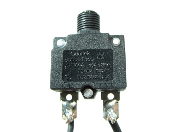
Another 15A breaker for a 13A cord. At this point, I am wondering if anybody is bothering to stock and use 13A breakers.
Inverter Transformer
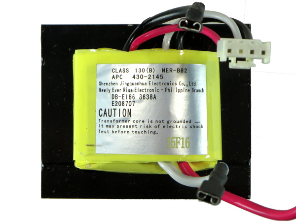
APC must be using this transformer in some other 550VA UPS variant with voltage regulation capability. Aside from the common battery terminal (bottom red wire) and the two inverter terminals (the loose black and white wires), the high voltage side also has three terminals, a telltale sign of the presence of a buck/boost tap that goes unused here.
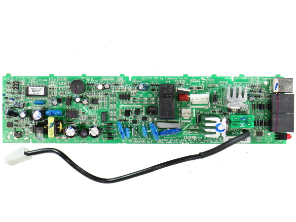
PCB Top
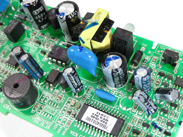
This is one tiny and tightly packed PCB that does everything. Starting from the left, we have the micro-controller and its support components, the power supply, a bunch of analog support components, a few MOVs for surge suppression, a pair of Y-class capacitors and one X-class cap for EMI filtering, the battery power transfer relay, the pair of inverter driver FETs on tiny heat sinks, a pair of 30A fuses for the battery and the Ethernet surge protection.
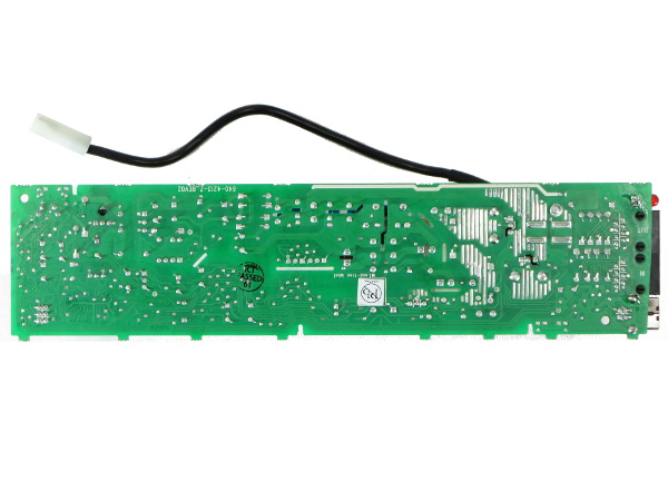
PCB Bottom
The soldering quality looks fine overall and there are no components to be found on this side.
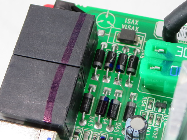
Network Surge Protection
Just like CyberPower, APC’s network surge protection is based on a bunch of 1N4007 diodes and a DIAC or similar device with a barely discernible ST logo on it. Unlike CyberPower, though, the double-sided board enables APC to use a much more compact layout.
Get Tom's Hardware's best news and in-depth reviews, straight to your inbox.
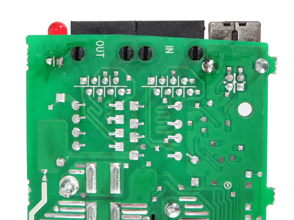
Protection Routing
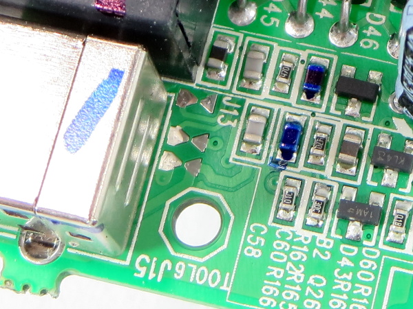
Also unlike CyberPower's LX, APC did try to at least length-match the pairs between RJ45 jacks when they couldn’t be properly routed as differential pairs. In the bottom-left corner, you can see two solder triangles facing tip-to-tip. Instead of tying the network surge protection directly to ground or through some form of surge suppression device, APC chose to use an open-air spark gap. It's a little crude, but should get the job done since the whole point of a surge protector is to provide a lower impedance and lower breakdown voltage path to ground than the connected equipment. This gap should break at around 700V vs. the 2000V minimum Ethernet isolation requirement.
From the solder flux around the LED leads and the left tab of the USB connector shield, some rework was apparently necessary on this board.
More Spark Gaps
The network surge protection is not the only place where APC uses spark gaps. It employs three more for the USB interface as well.
I thought the blue marker treatment was mainly to check that through-hole components were correctly seated. But one capacitor and what appears to be one inductor in the USB interface circuitry are apparently critical enough to warrant their own squiggles of approval.
Mix-and-Match Caps
Primary capacitors for the AC-DC power supply are from OST. Most secondary-side capacitors are from Chang, except for one Jaimicon next to the optoisolator.
A bunch of components in this picture also have permanent pen squiggles. There must be a manual inspection checklist for those through-hole components.
-
nukemaster Going to be interesting what you find in that RS/XS/BX(looks like them)?. Older units may have the same idle power draw issues you saw on the Tripp-lite unit.Reply
Thanks for posting this. -
Daniel Sauvageau I didn't have the necessary equipment to make waveform measurements at the time but you can find the BX1000's tear-down over here: http://www.tomshardware.com/picturestory/666-ups-battery-backup-tear-down.htmlReply
It is a completely different critter, using a DC-DC step-up converter and an output bridge instead of a transformer. The old BX's iron core transformer is used exclusively for the AVR function.
I would make input power measurements if I could but the reason I got started on this streak of UPS tear-downs is because my ~10 years old BX1000 died late last year: whenever I turn it on, it clicks for several seconds and then goes to battery power. Until I get around to fixing that, whatever measurements I make may be completely bogus. I'll probably end up writing a repair story about it when I get there. I have already had a quick look inside but the obvious suspects turned out to be dead ends.
Edit: I went to measure the BX1000's standby power while 'off' (the battery charger is still active in that state) and it draws 3.8W. I would not expect the normal 'on' power to be much over 1W above that since the only "power-hungry" thing that distinguishes the 'off' and 'on' states is operating the bypass relay. -
nukemaster I almost forgot you opened that unit. I wonder how close to my old XS1200 it is. Mine is warm on the side so I always guessed it was just a power waster.Reply
I also have a very old SmartUPS 1400(got it for free and just had to add the batteries) that runs warm enough(10 - 11 degrees above room temp if I trust its software). Cools down allot when the fan kicks in(run or charge).
Again, thanks for taking the time to take these things apart.
-
Daniel Sauvageau It does not take much power to get things slightly warm when there is only natural convection moving heat around and limited venting directly above the heat source to let that heat out.Reply -
Memhorder Thanks again Dan. Hey have you ever done the software side of things? I know it doesn't apply to this unit but say the Cyber Power you were hinting. I've noticed that using Cyber Power panel is just not accurate when trying to figure load in real time. The bar just doesn't move when you know the computer is sucking more juice under heavy use.Reply -
Daniel Sauvageau Reply
I haven't used PowerChute or any other manufacturer software in years. I simply set Windows' power and battery management settings to bypass third-party software. If I want to read the UPS' stats, basic parameters like battery state of charge, input voltage and output power are usually readable by HWInfo and other System Management Bus (SMB) monitoring tools.18149137 said:Hey have you ever done the software side of things?
-
alextheblue Glad to see APC doesn't skimp too much even on a low-end unit. One might perhaps mitigate the ground pin issue with a few "outlet saver" mini-extensions.Reply -
Onus I just don't like those output waveforms. Ok for light bulbs I suppose, they look ugly for electronics.Reply
Nice to see this one apparently got a thorough QC treatment.
-
photonboy Don't forget to ensure a UPS is compatible with the power supply. Many need a "pure sinewave" to support Active PFC (which is required for an 80-plus rating).Reply
Cyberpower has models with "PFC" right in the name to help avoid confusion. -
nukemaster I would say as long as you keep it away from some electric motors and other devices that just do not work properly on this waveform, It should not be an issue. It is not like most users run this way long term or anything.Reply
All of my computers have run ok on stepped wave so far(but the SmartUPS is sine). I know some active power factor power supplies(but not all) may not get along with this waveform however.
