Measurement Science: Taking Accurate IR Thermal Readings
If you thought that buying and unpacking an expensive infrared camera was all that it took to perform professional-level measurements, then it's time for a little lesson. We’ll share some of the knowledge that goes into generating accurate results.
Emissivity And Transmittance In Practice
Different Surfaces Spell Doom For Infrared Measurements
Every surface is made up of different materials and textures, yielding a certain emissivity that needs to be known before exact measurements can be performed. The better handheld infrared cameras can be calibrated accordingly. Or, alternatively, the manufacturer's software can be used. Unfortunately, many devices default to a value of 1.0, which you almost never see in practice. Consequently, all measurements performed with the emissivity set to 1.0 are useless.
Measurements and their results without the correct emissivity setting are completely useless!
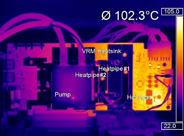
The following picture shows a great example of this. The colors are supposed to represent different temperatures. But what happened to the heat pipe and VRM? Even though they are extremely hot, they show up as dark (cold) in the picture. It's only once our special lacquer is applied do we see usable results. These spots can be seen in orange in the picture. Sure, you could also set the emissivity to match the composite material and aluminum, but this poses the problem that their emissivity changes significantly with increasing temperatures.
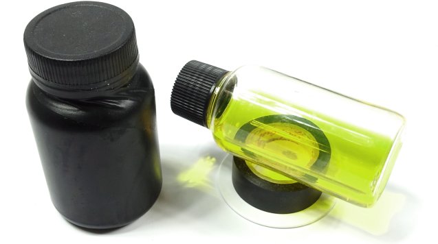
That's why we use a heat-resistant matte clear lacquer with a known emissivity that stays the same across its temperature range. These types of lacquers are used in industrial applications to protect electrical components from environmental hazards like humidity. This process is also colloquially called encapsulation. Unfortunately, these lacquers are very expensive, and you can't just buy them at a grocery store.
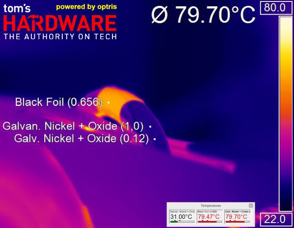
For heat pipes on CPU and GPU coolers, we can use our matte black measurement tape, which doesn't come cheap either. It works for temperatures up to 100 degrees Celsius, and we just couldn't do what we do without it.
Measuring the temperature of the 80-degree Celsius heat pipe fails miserably with the factory default emissivity setting of 1.0. That changes when we use the tape with its known 0.656 emissivity or after setting the correct emissivity of 0.12 for the heat pipe's material. However, the second approach changed by a factor of three across the temperature range that we saw in this benchmark, invalidating the results.
Using Lacquer To Measure Pins' Temperatures Correctly
It's important for any temperature measurement that there aren't any thermal variations attributable to emissivity in the measurement area, since this has a detrimental effect on the average result. The next two pictures illustrate the problem's significance.
Get Tom's Hardware's best news and in-depth reviews, straight to your inbox.
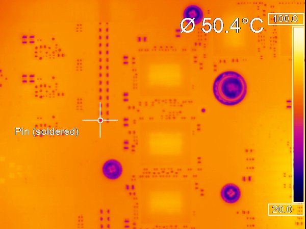
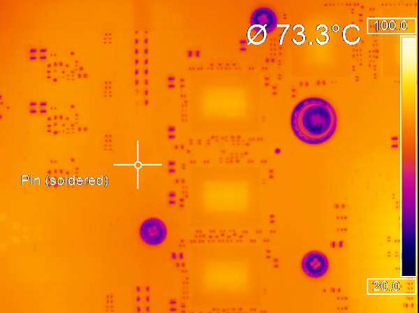
First we measure the temperature of a very hot VRM pin, which transfers heat straight to the board's copper pathways and surrounding areas. Due to the solder's lower emissivity, the pin actually looks like a 50-degree cold spot, though.
After applying lacquer to part of the pin, the entire area now has the same known and usable emissivity. The difference? A massive 23 degrees Celsius! Obviously, that's the difference between an accurate and a failed measurement.
Unfortunately, unless you have a solid background in temperature measurement, the results usually end up being too low, which we often see elsewhere online.
Looking Inside The Box
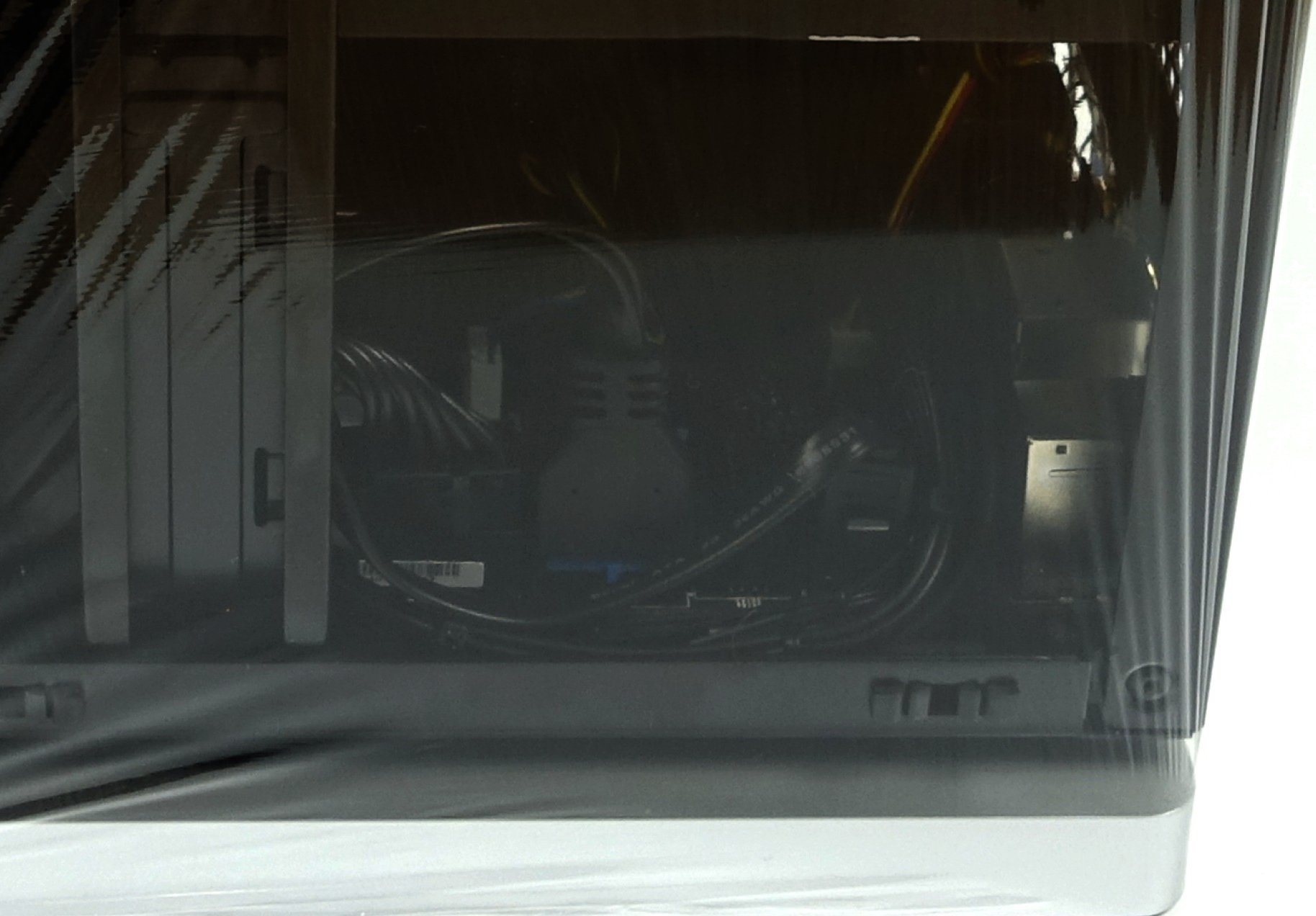
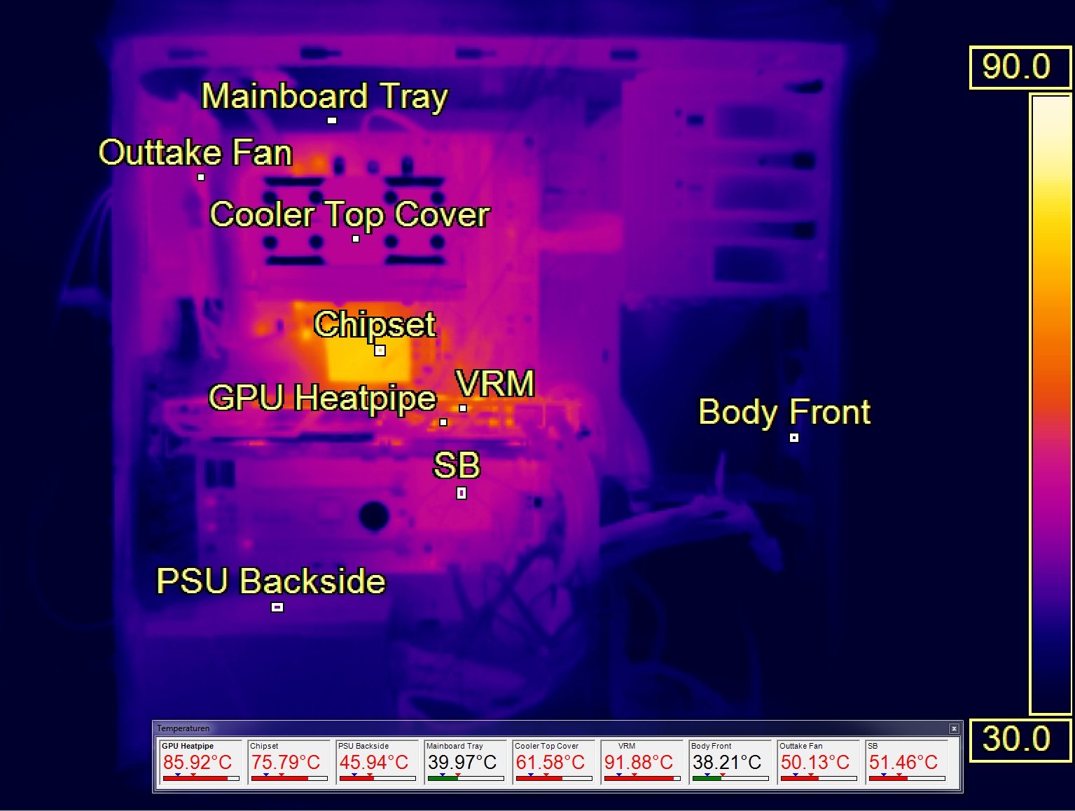
The best measurement methodology won't get you far if you can't look inside a closed PC case. We're using a trick that only works if you know the emissivity of a certain material. We need a foil, the thinner the better, that has a high enough transmittance to be used for temperature measurements.
The following picture shows a PC wrapped in the foil with nine different measurement points set up with the correct emissivity and transmittance. This way, hot air can't just escape from an open chassis.
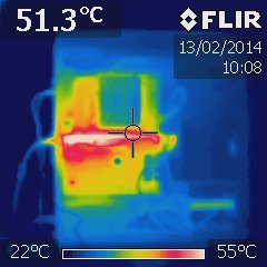
For comparison, we dug through our archives to show you what this kind of measurement looks like with a handheld infrared camera:
Current page: Emissivity And Transmittance In Practice
Prev Page Doing It Right Next Page Test System And Summary
Igor Wallossek wrote a wide variety of hardware articles for Tom's Hardware, with a strong focus on technical analysis and in-depth reviews. His contributions have spanned a broad spectrum of PC components, including GPUs, CPUs, workstations, and PC builds. His insightful articles provide readers with detailed knowledge to make informed decisions in the ever-evolving tech landscape
-
samopa Do they have some kind of API, to be connected to other system without using their proprietary software ?Reply -
dmnwlv Respect to tomshardware in its quest here to form a more complete picture in hardware tests and for presenting verifiable (factual) data in its reviews.Reply
I never bothered with all other sites' temperature charts/reviews on gpus ever since toms started doing this. -
FormatC Reply17594187 said:Do they have some kind of API, to be connected to other system without using their proprietary software ?
They have an API and a helpful documentation too. :)
-
Flying-Q I like all the isolation and standardisation you use for consistent, repeatable and accurate measurement. I have a question though: would a cowl over the CPU, chipset and memory make any difference to preventing reflected heat contribution from those components?Reply -
FormatC Only, if the waves goes in the same direction. Upgoing heat is no problem (90° crossing).Reply
I tried it to cover it with a thick, black foam plate - no difference. :) -
dr3cks4u Very good article, thanks for that. I´m sure a lot of people don´t know how time-consuming this kind of measurement is. Question @ Igor: Is the emissivity of the used lacquer constant across the electromagnetic spectrum (=grey body) or is it just known for the camera´s spectral range (7,5-13,0 microns)?Reply
