Why you can trust Tom's Hardware
Advanced Transient Response Tests
For details about our transient response testing, please click here.
In the real world, power supplies are always working with loads that change. It's of immense importance, then, for the PSU to keep its rails within the ATX specification's defined ranges. The smaller the deviations, the more stable your PC will be with less stress applied to its components.
We should note that the ATX spec requires capacitive loading during the transient rests, but in our methodology, we also choose to apply a worst case scenario with no additional capacitance on the rails.
Advanced Transient Response at 20% – 20ms
| Voltage | Before | After | Change | Pass/Fail |
|---|---|---|---|---|
| 12V | 12.247V | 12.133V | 0.93% | Pass |
| 5V | 5.078V | 4.993V | 1.67% | Pass |
| 3.3V | 3.315V | 3.189V | 3.80% | Pass |
| 5VSB | 4.992V | 4.949V | 0.86% | Pass |
Advanced Transient Response at 20% – 10ms
| Voltage | Before | After | Change | Pass/Fail |
|---|---|---|---|---|
| 12V | 12.249V | 12.133V | 0.95% | Pass |
| 5V | 5.079V | 4.995V | 1.65% | Pass |
| 3.3V | 3.315V | 3.204V | 3.35% | Pass |
| 5VSB | 4.993V | 4.950V | 0.86% | Pass |
Advanced Transient Response at 20% – 1ms
| Voltage | Before | After | Change | Pass/Fail |
|---|---|---|---|---|
| 12V | 12.250V | 12.127V | 1.00% | Pass |
| 5V | 5.080V | 5.016V | 1.26% | Pass |
| 3.3V | 3.316V | 3.205V | 3.35% | Pass |
| 5VSB | 4.993V | 4.954V | 0.78% | Pass |
Advanced Transient Response at 50% – 20ms
| Voltage | Before | After | Change | Pass/Fail |
|---|---|---|---|---|
| 12V | 12.211V | 12.031V | 1.47% | Pass |
| 5V | 5.058V | 4.978V | 1.58% | Pass |
| 3.3V | 3.294V | 3.172V | 3.70% | Pass |
| 5VSB | 4.948V | 4.901V | 0.95% | Pass |
Advanced Transient Response at 50% – 10ms
| Voltage | Before | After | Change | Pass/Fail |
|---|---|---|---|---|
| 12V | 12.211V | 12.071V | 1.15% | Pass |
| 5V | 5.058V | 4.962V | 1.90% | Pass |
| 3.3V | 3.294V | 3.170V | 3.76% | Pass |
| 5VSB | 4.948V | 4.892V | 1.13% | Pass |
Advanced Transient Response at 50% – 1ms
| Voltage | Before | After | Change | Pass/Fail |
|---|---|---|---|---|
| 12V | 12.210V | 12.102V | 0.88% | Pass |
| 5V | 5.058V | 4.963V | 1.88% | Pass |
| 3.3V | 3.295V | 3.175V | 3.64% | Pass |
| 5VSB | 4.949V | 4.897V | 1.05% | Pass |
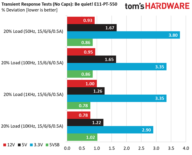
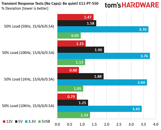
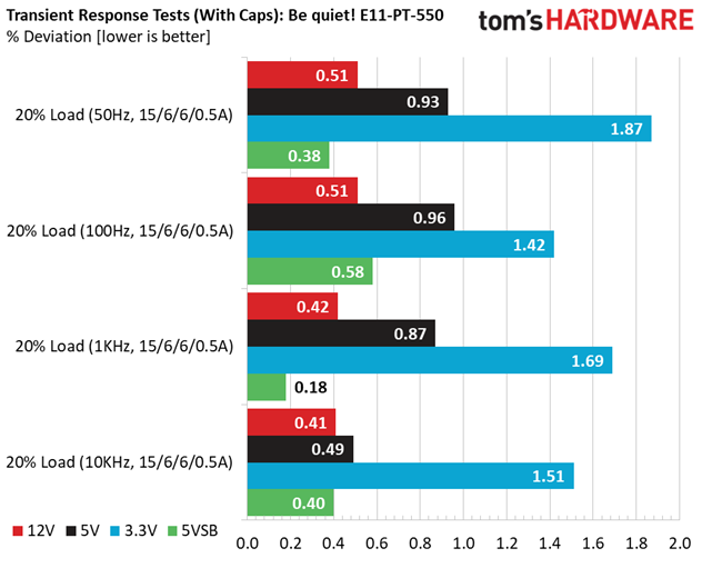
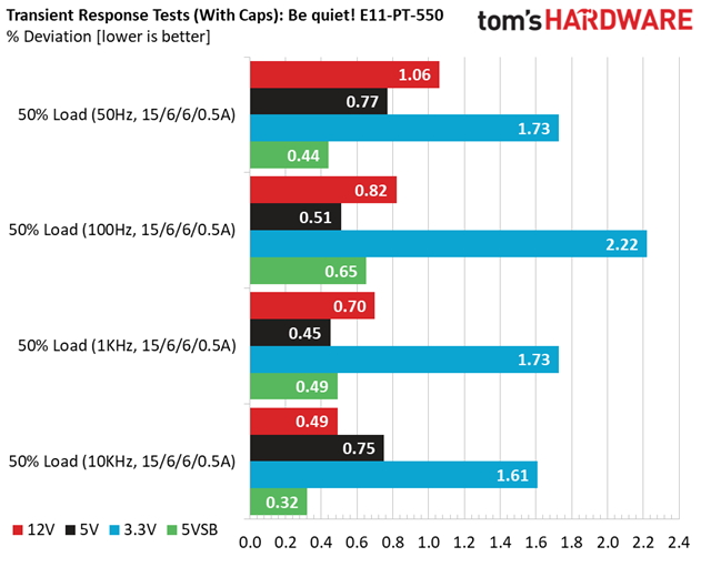
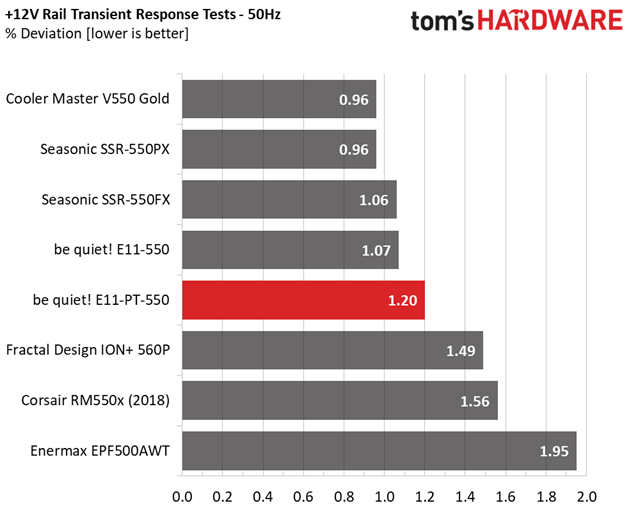
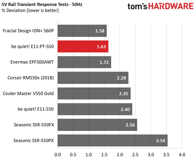
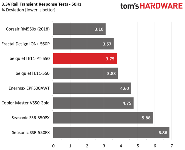
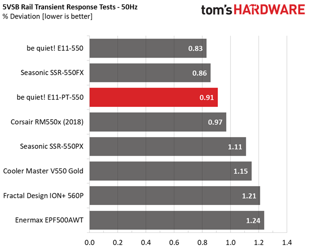
The transient response is at satisfactory levels at +12V, and it is actually good at 5V and 5VSB. The deviation at 3.3V is not that high, but the voltage levels drop too low, below 3.2V.
Turn-On Transient Tests
In the next set of tests, we measure the PSU's response in simpler transient load scenarios—during its power-on phase. Ideally, we don't want to see any voltage overshoots or spikes since those put a lot of stress on the DC-DC converters of installed components.
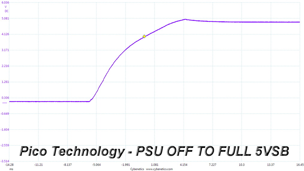
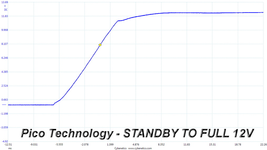
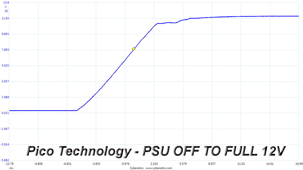
There is a small voltage overshoot at 5VSB. The slopes at +12V are smoother.
Power Supply Timing Tests
There are several signals generated by the power supply, which need to be within specified, by the ATX spec, ranges. If they are not, there can be compatibility issues with other system parts, especially mainboards. From the year 2020, the PSU's Power-on time (T1) has to be lower than 150ms and the PWR_OK delay (T3) from 100 to 150ms, to be compatible with the Alternative Sleep Mode.
Get Tom's Hardware's best news and in-depth reviews, straight to your inbox.
PSU Timings Table
| T1 (Power-on time) & T3 (PWR_OK delay) | ||
|---|---|---|
| Load | T1 | T3 |
| 20% | 70ms | 136ms |
| 50% | 68ms | 134ms |
The PWR_OK delay is within the 100-150ms range, so the PSU does support the alternative sleep mode, which is recommended by the ATX spec.
Ripple Measurements
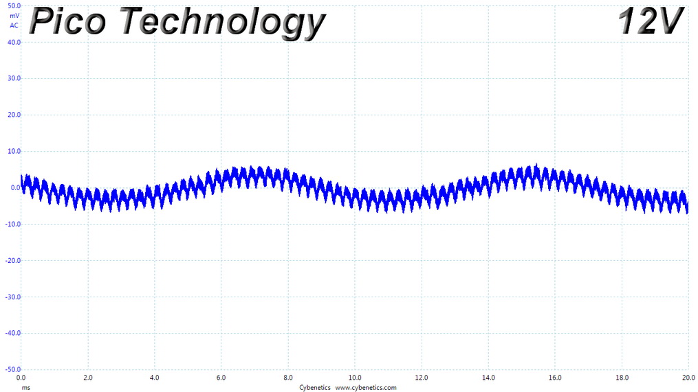
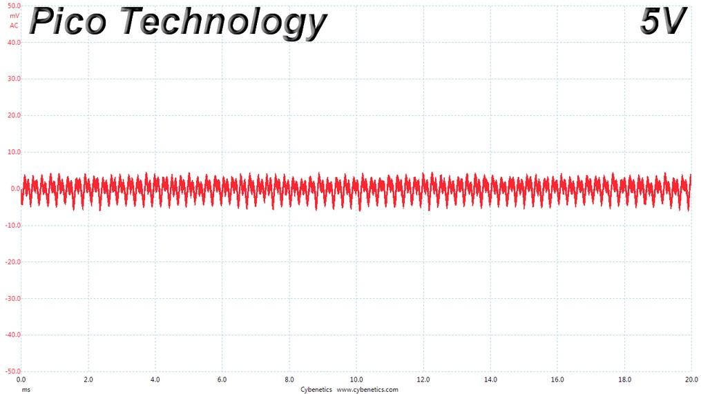
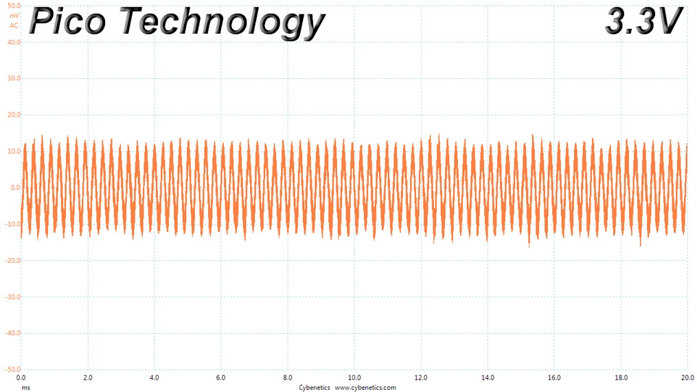
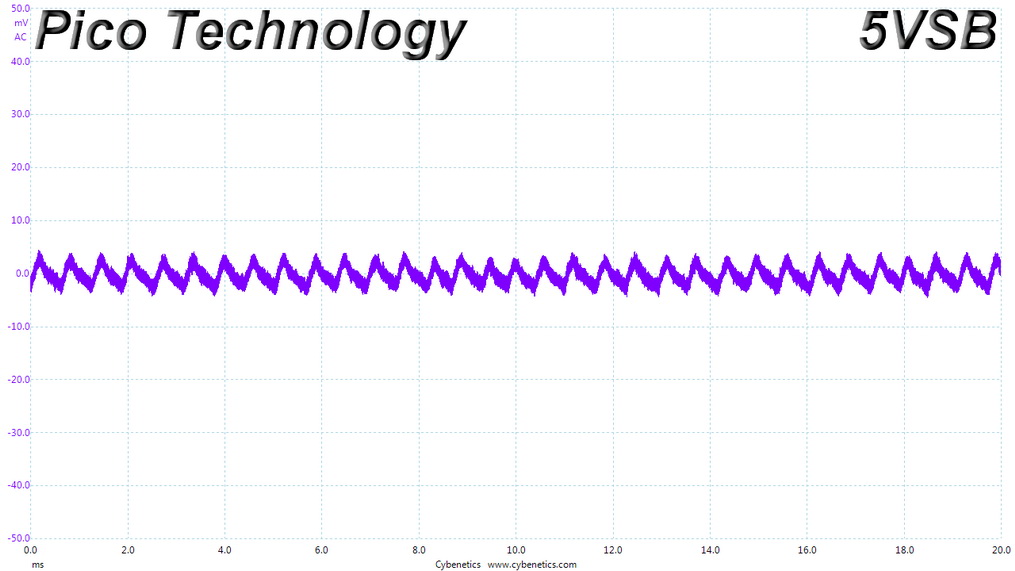
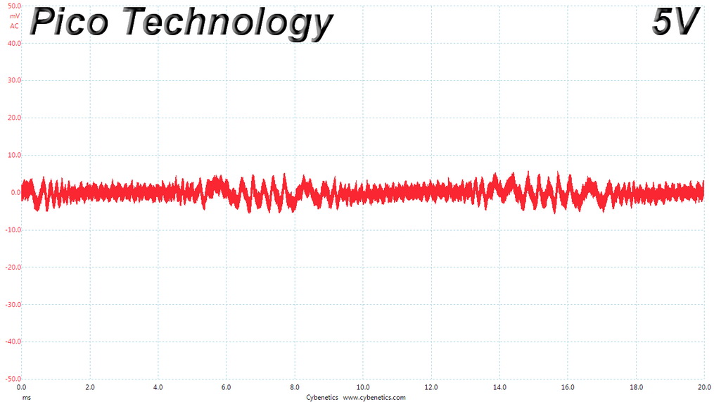
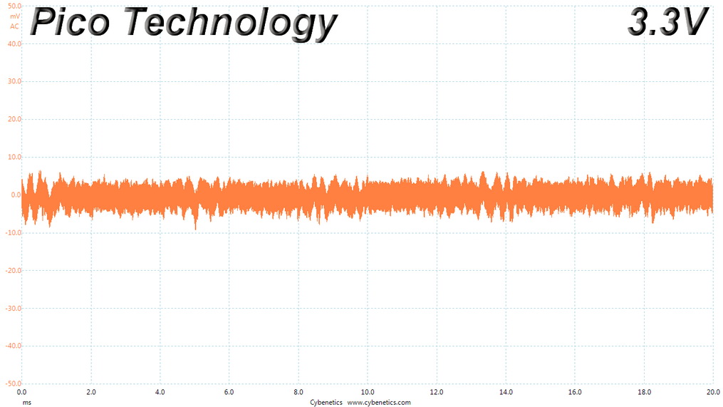
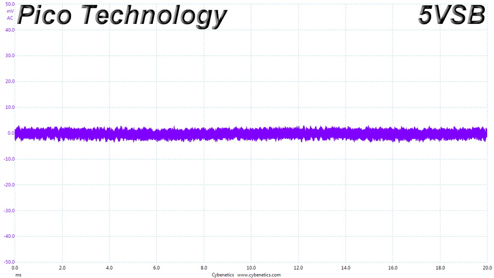
Ripple represent the AC fluctuations (periodic) and noise (random) found in the PSU's DC rails. This phenomenon significantly decreases the capacitors' lifespan because it causes them to run hotter. A 10-degree Celsius increase can cut into a cap's useful life by 50%. Ripple also plays an important role in overall system stability, especially when overclocking is involved.
The ripple limits, according to the ATX specification, are 120mV (+12V) and 50mV (5V, 3.3V, and 5VSB).
Ripple Table
| Test | 12V | 5V | 3.3V | 5VSB | Pass/Fail |
|---|---|---|---|---|---|
| 10% Load | 5.9 mV | 5.8 mV | 13.1 mV | 5.2 mV | Pass |
| 20% Load | 7.3 mV | 6.1 mV | 12.7 mV | 5.3 mV | Pass |
| 30% Load | 10.7 mV | 6.5 mV | 14.5 mV | 5.6 mV | Pass |
| 40% Load | 14.0 mV | 6.3 mV | 15.5 mV | 6.3 mV | Pass |
| 50% Load | 16.0 mV | 7.0 mV | 16.6 mV | 6.4 mV | Pass |
| 60% Load | 18.5 mV | 7.6 mV | 16.8 mV | 6.4 mV | Pass |
| 70% Load | 30.4 mV | 11.0 mV | 19.4 mV | 6.9 mV | Pass |
| 80% Load | 31.3 mV | 11.2 mV | 22.3 mV | 7.7 mV | Pass |
| 90% Load | 31.4 mV | 12.0 mV | 23.5 mV | 7.9 mV | Pass |
| 100% Load | 40.7 mV | 14.1 mV | 24.9 mV | 9.9 mV | Pass |
| 110% Load | 39.4 mV | 14.0 mV | 28.6 mV | 10.5 mV | Pass |
| Crossload 1 | 14.5 mV | 12.2 mV | 34.0 mV | 9.6 mV | Pass |
| Crossload 2 | 38.3 mV | 12.8 mV | 18.1 mV | 7.7 mV | Pass |
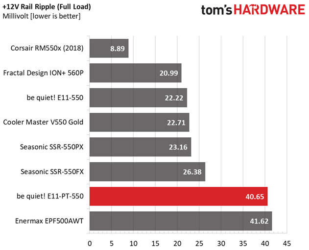
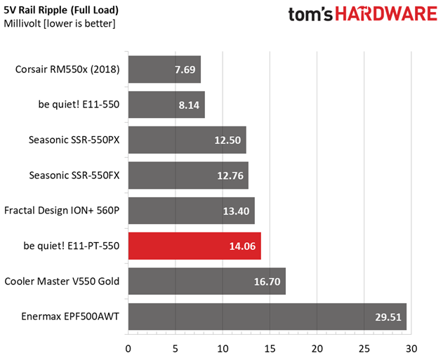
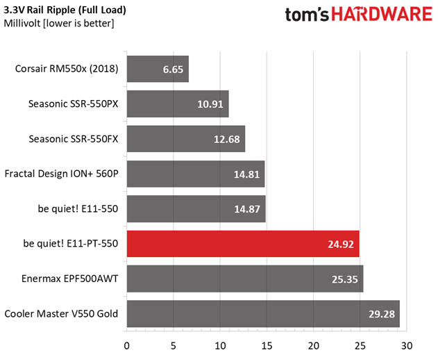
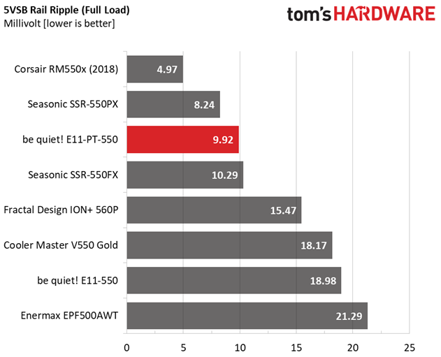
The ripple suppression is not up to the competition's levels, at +12V and 3.3V.
Ripple At Full Load
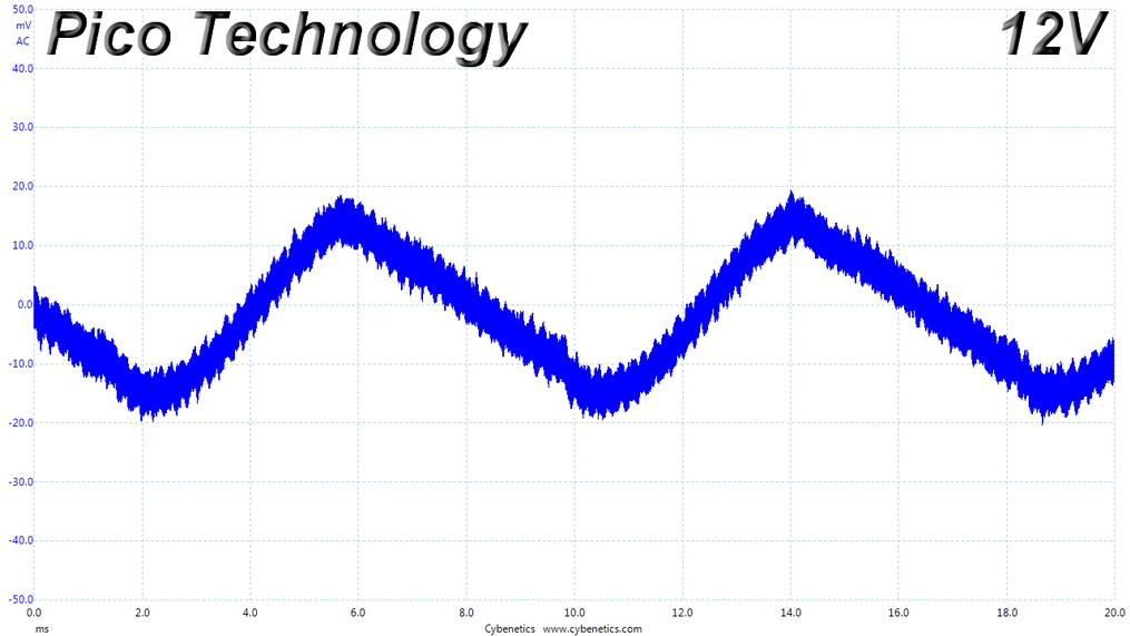
Ripple Full Load Scope Shots
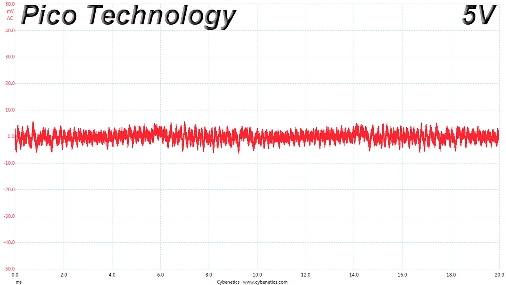
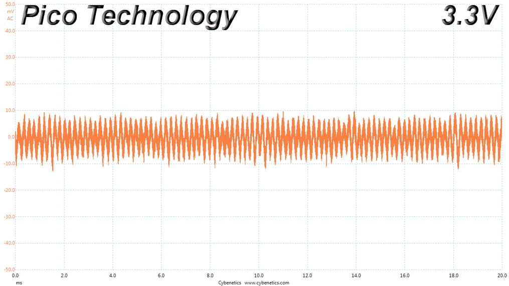
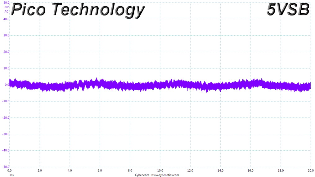
Ripple At 110% Load
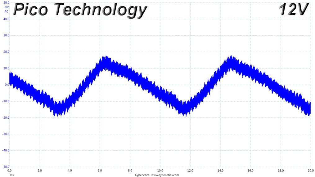
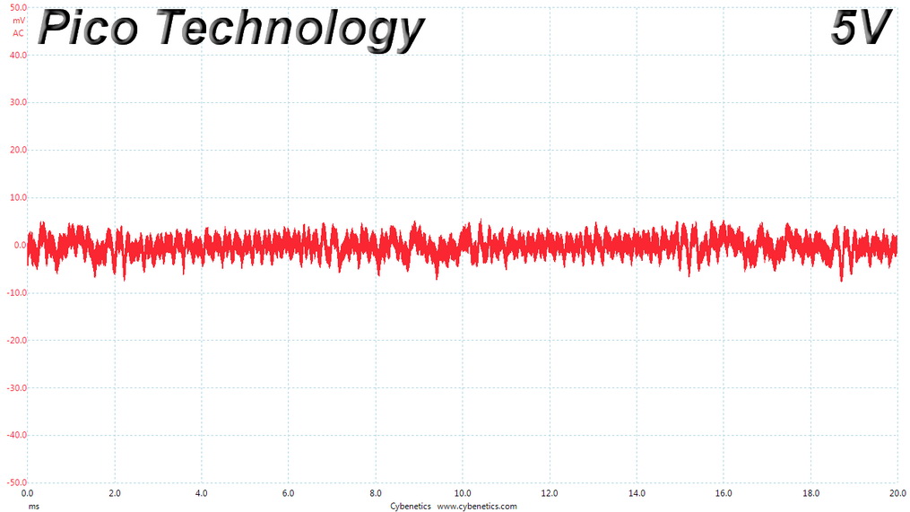
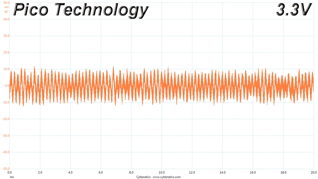
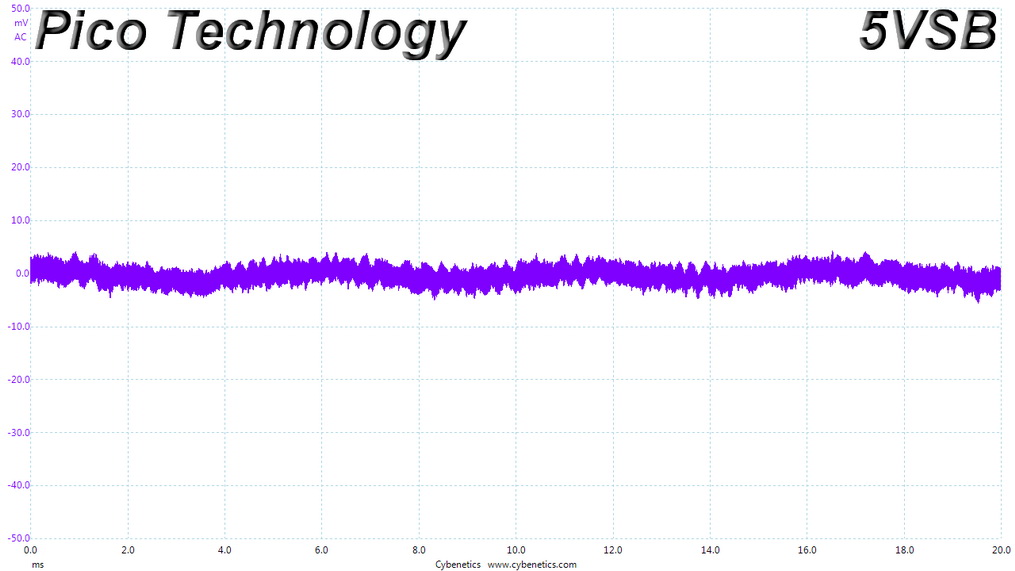
Ripple At Cross-Load 1
Ripple At Cross-Load 2
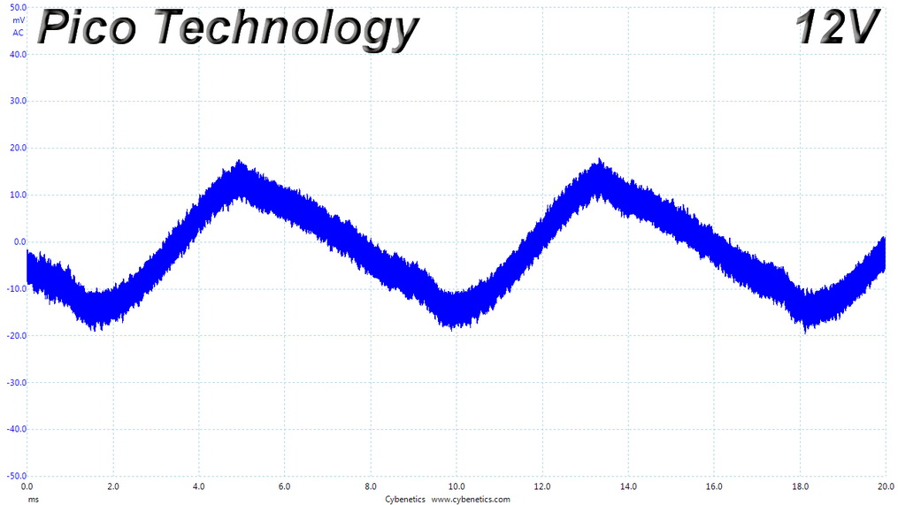
Ripple CL2 Load Scope Shots
EMC Pre-Compliance Testing – Average & Quasi-Peak EMI Detector Results
Electromagnetic Compatibility (EMC) is the ability of a device to operate properly in its environment without disrupting the proper operation of other nearby devices.
Electromagnetic Interference (EMI) stands for the electromagnetic energy a device emits, and it can cause problems in other nearby devices if too high. For example, it can be the cause of increased static noise in your headphones or/and speakers.
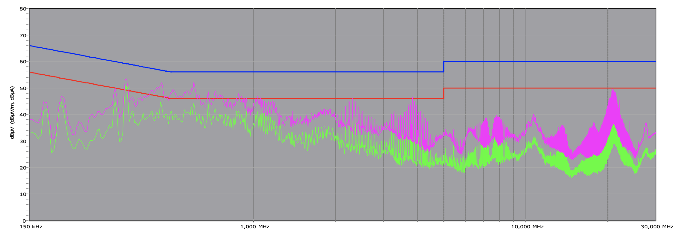
There is one spur going over the limit at 342 KHz, with the average detector, but everything is fine with the Quasi-Peak detector, which is more accurate.
MORE: Best Power Supplies
MORE: How We Test Power Supplies
MORE: All Power Supply Content
Current page: Transient Response Tests, Timing Tests, Ripple Measurements and EMC Pre-Compliance Testing
Prev Page Protection Features, DC Power Sequencing, Cross-Load Tests and Infrared Images Next Page Performance, Noise and Efficiency
Aris Mpitziopoulos is a contributing editor at Tom's Hardware, covering PSUs.
-
JohnBonhamsGhost how can it be both;Reply
+ FORCompatible with the alternative sleep mode
&
- AGAINSTNot compatible with the alternative sleep mode
?? -
chaz_music Great write up, Aris.Reply
I was not aware that the Intel PSU specs were coming out this summer (July 2020), which is great. BTW, take a look at the ripple graph on page 3. I think the Y axis is labelled wrong. Also, why no data on the 115VAC holdup? That is critical for people using this PSU with a standard UPS. Most of desktop UPS systems (think: inexpensive) are standby / line interactive and have a change over relay with transfer times in the 4-20mSec time range. Any PSU that is lower than that will have problems keeping the CPU alive during an outage. Too bad there is not a signal from the PSU to the CPU to power back. That signal could be used everywhere to cause SSDs and RAID arrays to go into save mode, and other subsystems to power down (Ethernet, USB, audio, etc.).
The Cybernetics Labs testing methods are spot on for the "how and why". There are minor tweaks that I would make, but overall, excellent testing methodology. The UPS market has cheated on efficiency for decades by testing a cold UPS for the product documentation. Everything should be at thermal steady state for true efficiency numbers, and at realistic operating conditions. The only parts that benefit from being warm are the electrolytic caps, except for their lifetime. I believe it is still true that all electrolytic caps have a decrease in ESR as they get warmer, up to a point depending on the electrolyte used. Everything else gets worse efficiency with heat: MOSFETS, XFMR, filter inductors, etc.
It is good to see better efficiency numbers in lower power PSUs. I searched for along time on my NAS build for at least a 80+ gold rated 200-250W PSU. I finally found an FSP 250W unit that was in an SFX package. A great article would be one who has the better/best low power PSUs especially in the area of efficiency.
Several points that I believe get overlooked in thinking about efficiency:
How much energy are you going to use to cool the building that the PSU is in? Usually around 50% of the total PSU power used for the months that HVAC is being used. This also gets overlooked with cost comparisons for LED bulbs versus incandescent bulbs. The HVAC savings is enormous.
The concept that the payback period for a higher cost efficient PSU does not give good ROI. I reuse most of my PSUs unless the caps look poor or I have had it being used at over 50-60% rated power for much of its life. With PSU getting warranties of 5years+, the added cost should be amortized over a longer period. Maybe over two chassis builds?
Thanks for the great article.
BR,
Charles -
Aris_Mp Reply
this is an obvious error. It IS compatible with the alternative sleep mode. Already asked to fix this.JohnBonhamsGhost said:how can it be both;
+ FORCompatible with the alternative sleep mode
&
- AGAINSTNot compatible with the alternative sleep mode
?? -
Aris_Mp Replychaz_music said:Great write up, Aris.
I was not aware that the Intel PSU specs were coming out this summer (July 2020), which is great. BTW, take a look at the ripple graph on page 3. I think the Y axis is labelled wrong. Also, why no data on the 115VAC holdup? That is critical for people using this PSU with a standard UPS. Most of desktop UPS systems (think: inexpensive) are standby / line interactive and have a change over relay with transfer times in the 4-20mSec time range. Any PSU that is lower than that will have problems keeping the CPU alive during an outage. Too bad there is not a signal from the PSU to the CPU to power back. That signal could be used everywhere to cause SSDs and RAID arrays to go into save mode, and other subsystems to power down (Ethernet, USB, audio, etc.).
The Cybernetics Labs testing methods are spot on for the "how and why". There are minor tweaks that I would make, but overall, excellent testing methodology. The UPS market has cheated on efficiency for decades by testing a cold UPS for the product documentation. Everything should be at thermal steady state for true efficiency numbers, and at realistic operating conditions. The only parts that benefit from being warm are the electrolytic caps, except for their lifetime. I believe it is still true that all electrolytic caps have a decrease in ESR as they get warmer, up to a point depending on the electrolyte used. Everything else gets worse efficiency with heat: MOSFETS, XFMR, filter inductors, etc.
It is good to see better efficiency numbers in lower power PSUs. I searched for along time on my NAS build for at least a 80+ gold rated 200-250W PSU. I finally found an FSP 250W unit that was in an SFX package. A great article would be one who has the better/best low power PSUs especially in the area of efficiency.
Several points that I believe get overlooked in thinking about efficiency:
How much energy are you going to use to cool the building that the PSU is in? Usually around 50% of the total PSU power used for the months that HVAC is being used. This also gets overlooked with cost comparisons for LED bulbs versus incandescent bulbs. The HVAC savings is enormous.
The concept that the payback period for a higher cost efficient PSU does not give good ROI. I reuse most of my PSUs unless the caps look poor or I have had it being used at over 50-60% rated power for much of its life. With PSU getting warranties of 5years+, the added cost should be amortized over a longer period. Maybe over two chassis builds?Thanks for the great article.
BR,
Charles
Hi Charles, and thank you for your comments.
The hold-up time is almost identical between 115V and 230V. The change is in the inrush current. I agree with you, the hold-up time is of immense importance.
CL ripple graph in page 3, I cannot find anything out of order.
If you have any suggestions on how to improve the Cybenetics methodology, they always hear opinions and are ready to make changes, if those are for the best.
About efficiency, diodes have lower voltage drops at increased temperatures as well, and this plays a major role especially in bridge rectifiers.
Thank you for the other two points you mention. Indeed the cost of dealing with the added thermal load of lower efficiency PSUs is significant. -
Co BIY Interesting cross-hatching (in solder?) on the back of the board in the FET and VRM photo.Reply
Can someone explain the purpose of that ? Heat Sink ? Heat dissipation ?
