Why you can trust Tom's Hardware
We are using the following system for this build:
| CPU | Intel Core i9-9900K |
| Motherboard | Asus Maximus XI Hero WiFi |
| Memory | G.Skill Trident Z Royal 32 GB (4x 8 GB, 3600 MHz) |
| Graphics | Nvidia GeForce RTX 2070 Super Founder’s Edition |
| CPU Cooling | Phanteks Glacier One 360MP AIO |
| Row 5 - Cell 0 | Noctua NT-H2 Thermal Paste |
| Storage | Corsair Force Series MP510 NVMe SSD, 480GB |
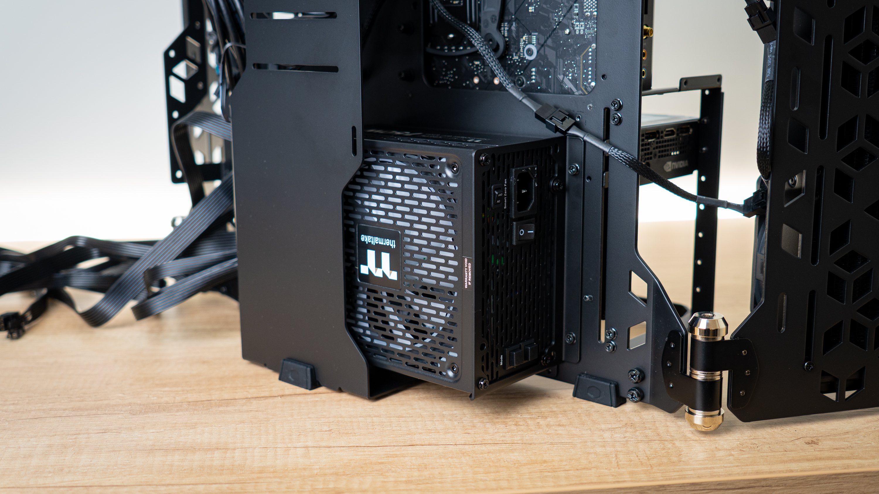
| Power Supply | Thermaltake ToughPower GF2 ARGB 750W PSU |
Because we’re not following the usual recipe and this is more of a showcase, I decided to ditch the standard air-cooled setup and grab a few other parts I have around the office to create a build. This included using a 360mm AIO from Phanteks, with its pretty infinity-mirror CPU block, an RGB-enabled Thermaltake PSU and G.Skill’s oh-so-shiny Trident Z Royal memory.
Step 1: Standoff Installation
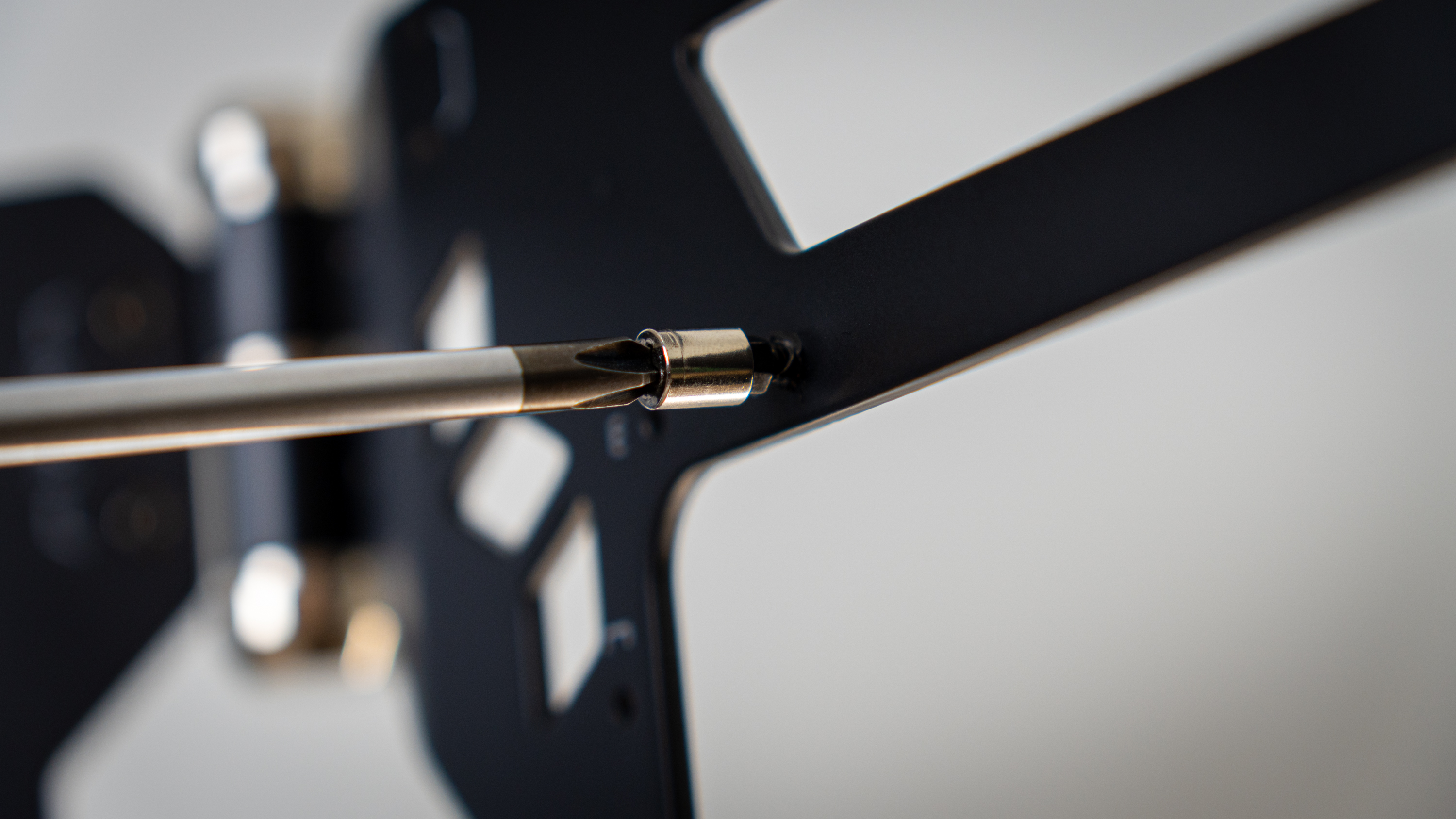
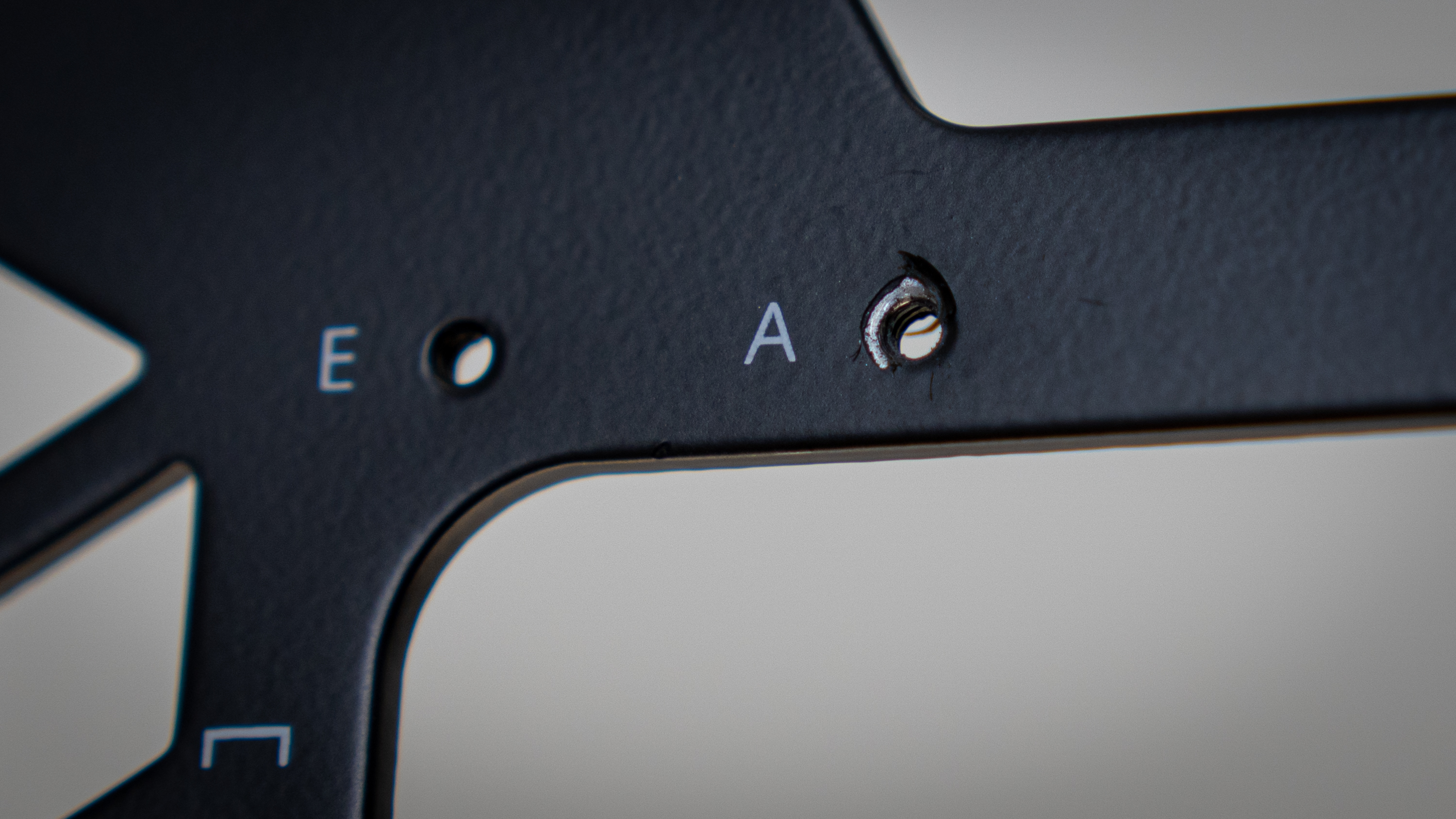
Proceeding with the build, I immediately ran into my first issue: installing the motherboard standoffs. Knowing where to put them wasn’t the issue as it’s clearly labelled, but the pretty paintjob also found its way into the screw threads, which made installing the standoffs very challenging.
There was a lot of paint to work through, and getting the standoffs to bite into the threads was difficult. When they eventually bit, a significant amount of force was required to get them to turn fully into the threading, and in the end it took me about 20 minutes to get the nine standoffs required for an ATX motherboard installed.
Of course, there is a flipside to this issue: Ensuring the threads remain clear is more work in the factory, and it doesn’t look as good for the final end-product. This way, only the threads that you actually use end up with visible steel, but they’re covered with a screw so it doesn’t matter – it just takes a bit more labor from the system builder’s side.
Step 2: Motherboard and GPU Installation:
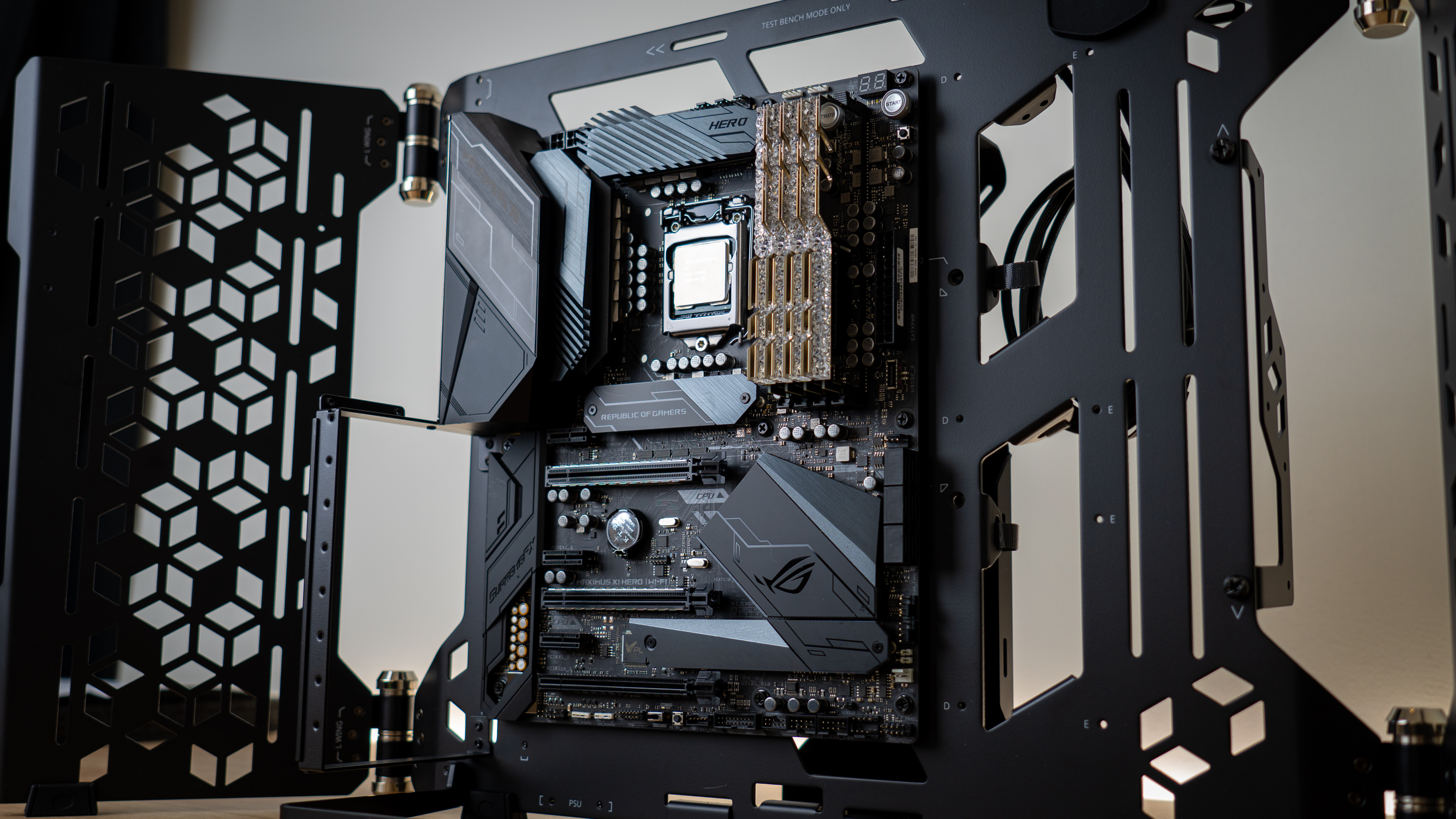
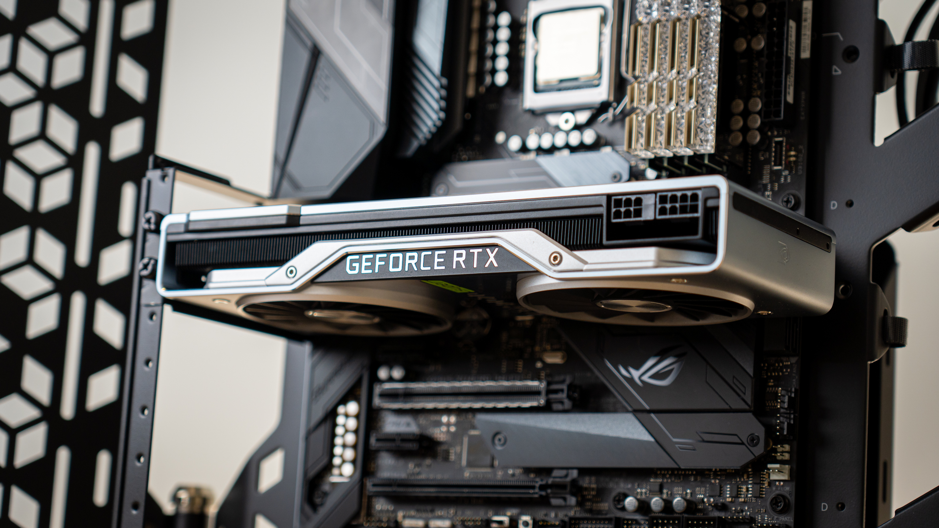
After this, the motherboard and GPU dropped right into place. Without an IO shield cutout, lining the motherboard up with the standoffs was very easy. I did have to place the chassis on its back for this, though, as there was no anchoring standoff, and the GPU sagged too much with its IO shield unsecured.
Step 3: CPU Cooler Installation
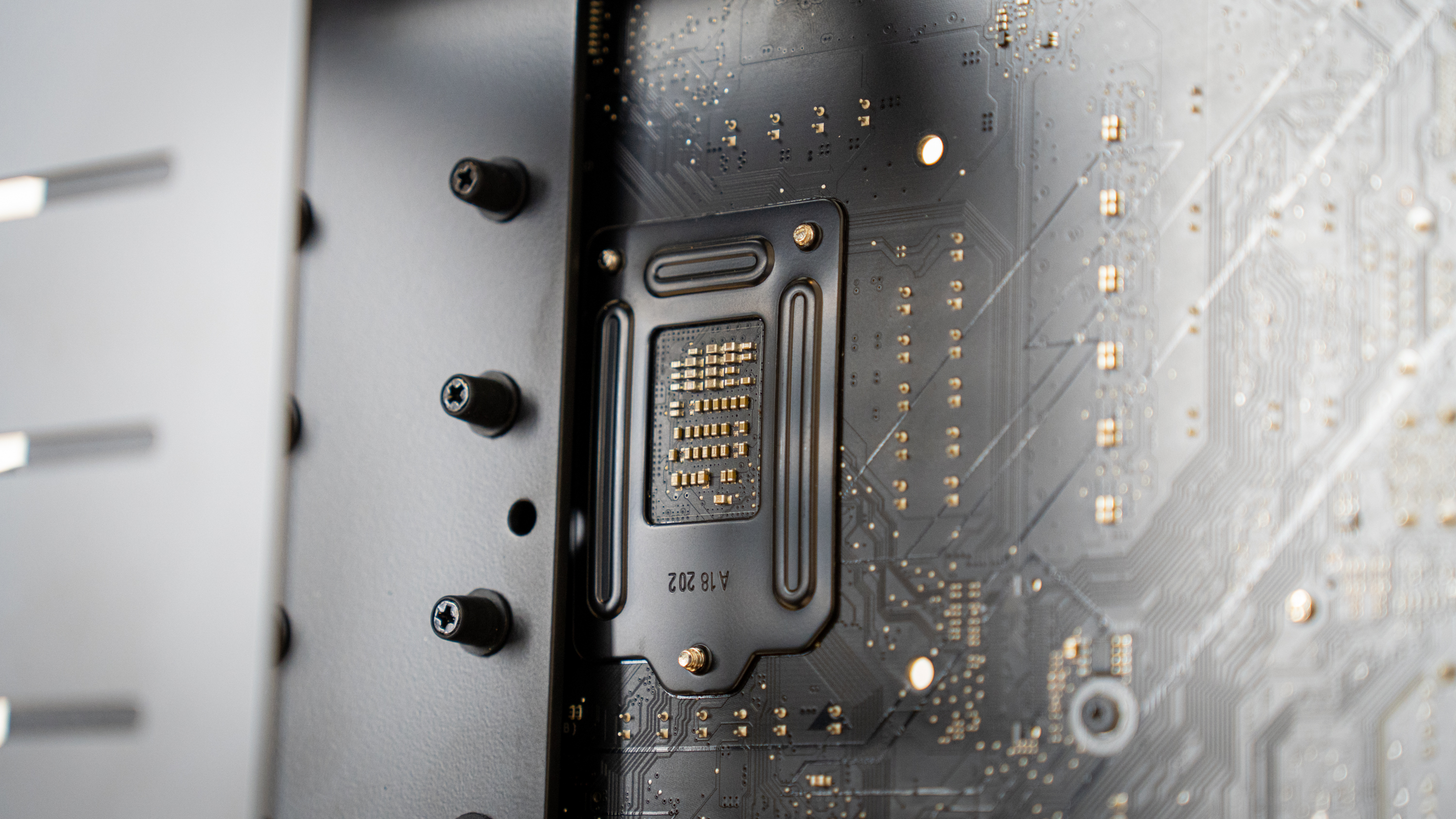
At this stage, I ran into another issue: The rear cutout for CPU coolers was not big enough to access the back of the LGA1151 socket. With that unavoidable issue, I proceeded to uninstall the GPU, motherboard, fix the cooler’s backplate, and re-install the lot.
Get Tom's Hardware's best news and in-depth reviews, straight to your inbox.
Now, if you’re a CPU cooler reviewer, this might be rather inconvenient as you’d need to uninstall the entire system to change cooler – but most people using this chassis won’t be swapping coolers all the time. And no one reviewing CPU coolers should be doing so in an open-air setup. The reason why the cutout is smaller is because of the VESA 100 mount.
Step 4: PSU Installation
The Thermaltake PSU dropped right into place.
Step 5: Cable Management
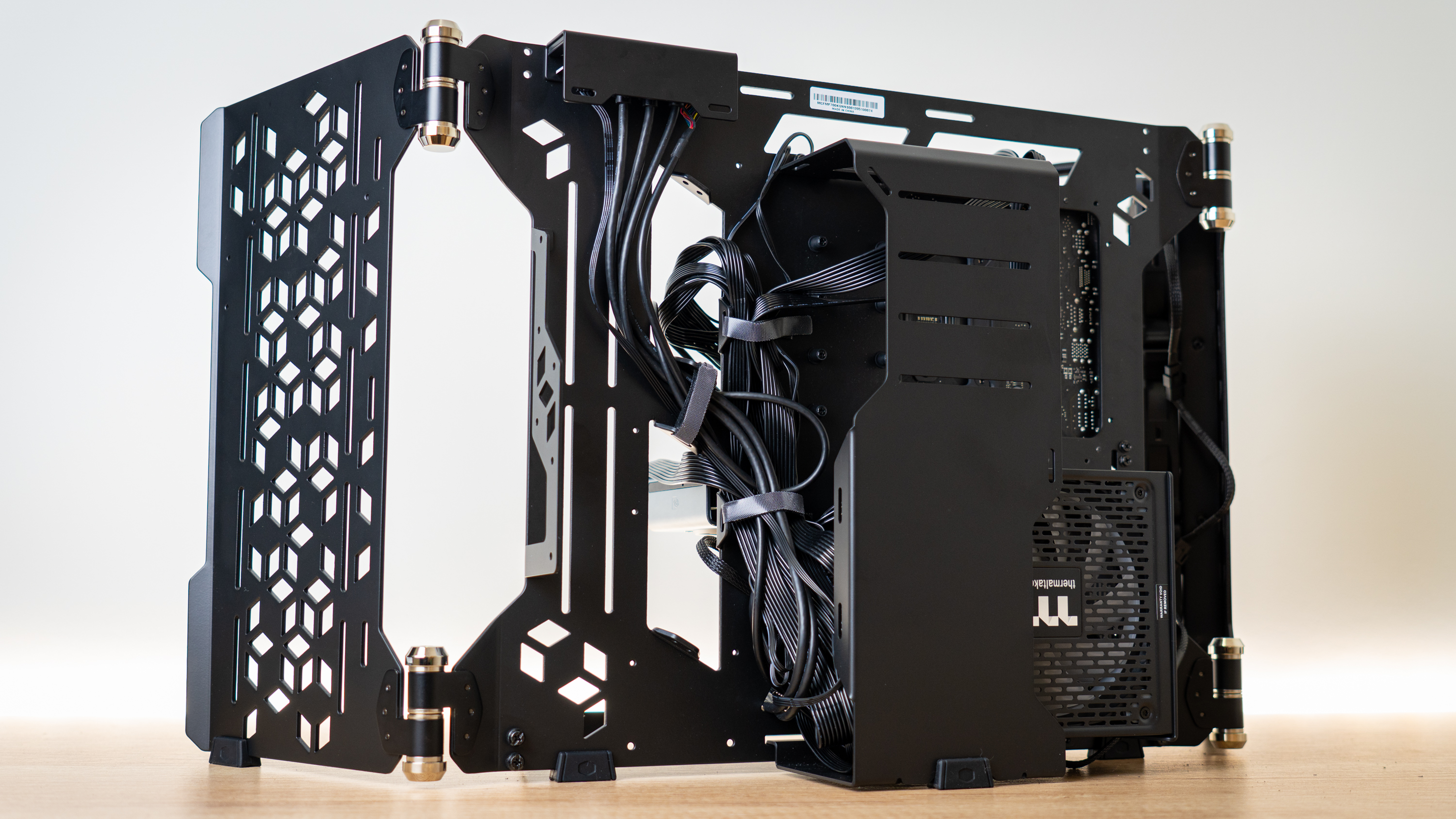
To my surprise, cable management actually went quite well. You would expect that cable hiding and routing would be absolutely dreadful in a chassis that’s as open as this one, but it wasn’t. I was able to chuck most of the cables into two horizontal Velcro straps, and I tied the IO shield’s cables down through an angled strap. This would come in handy later when switching to test-bench mode, as it would need to be moved to the other side of the chassis for accessibility.
Step 6: Place In a Corner and Fire ‘er Up!
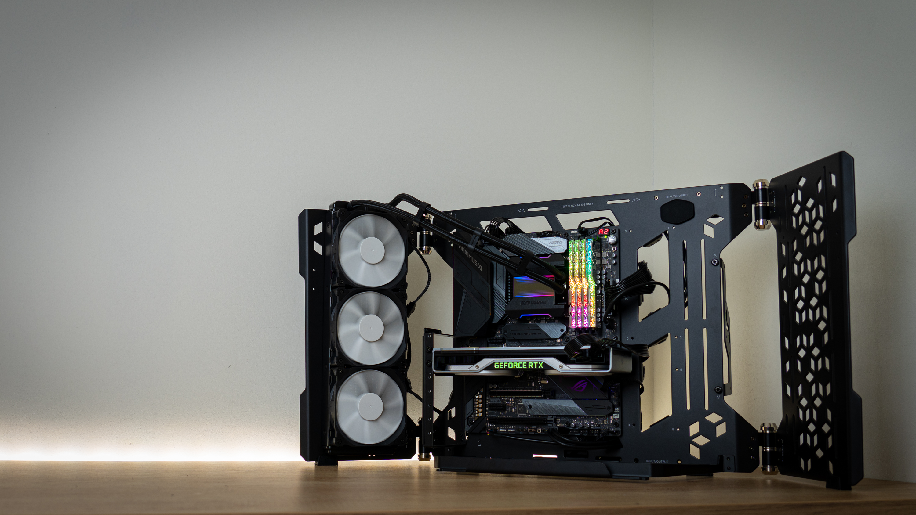
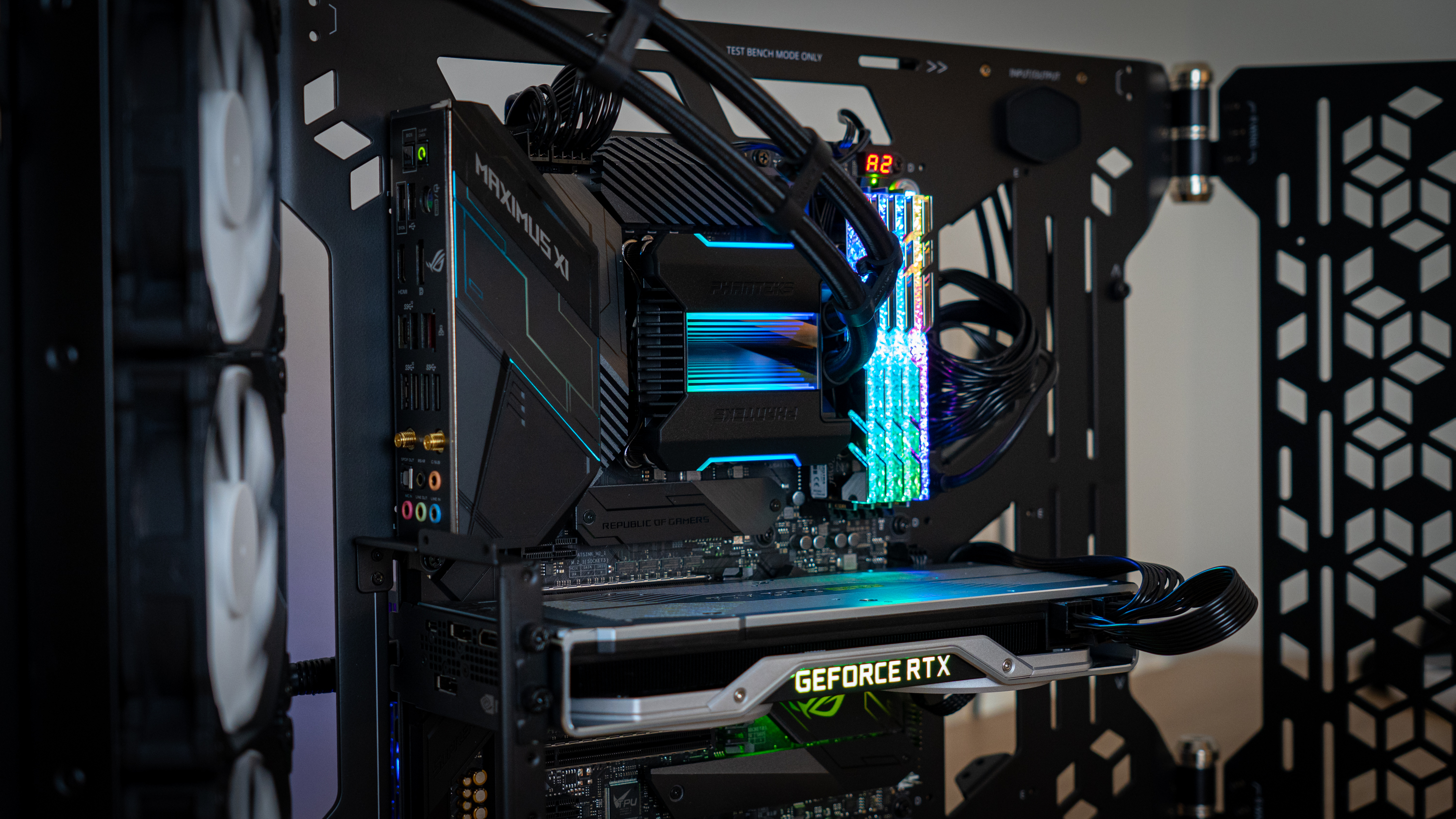
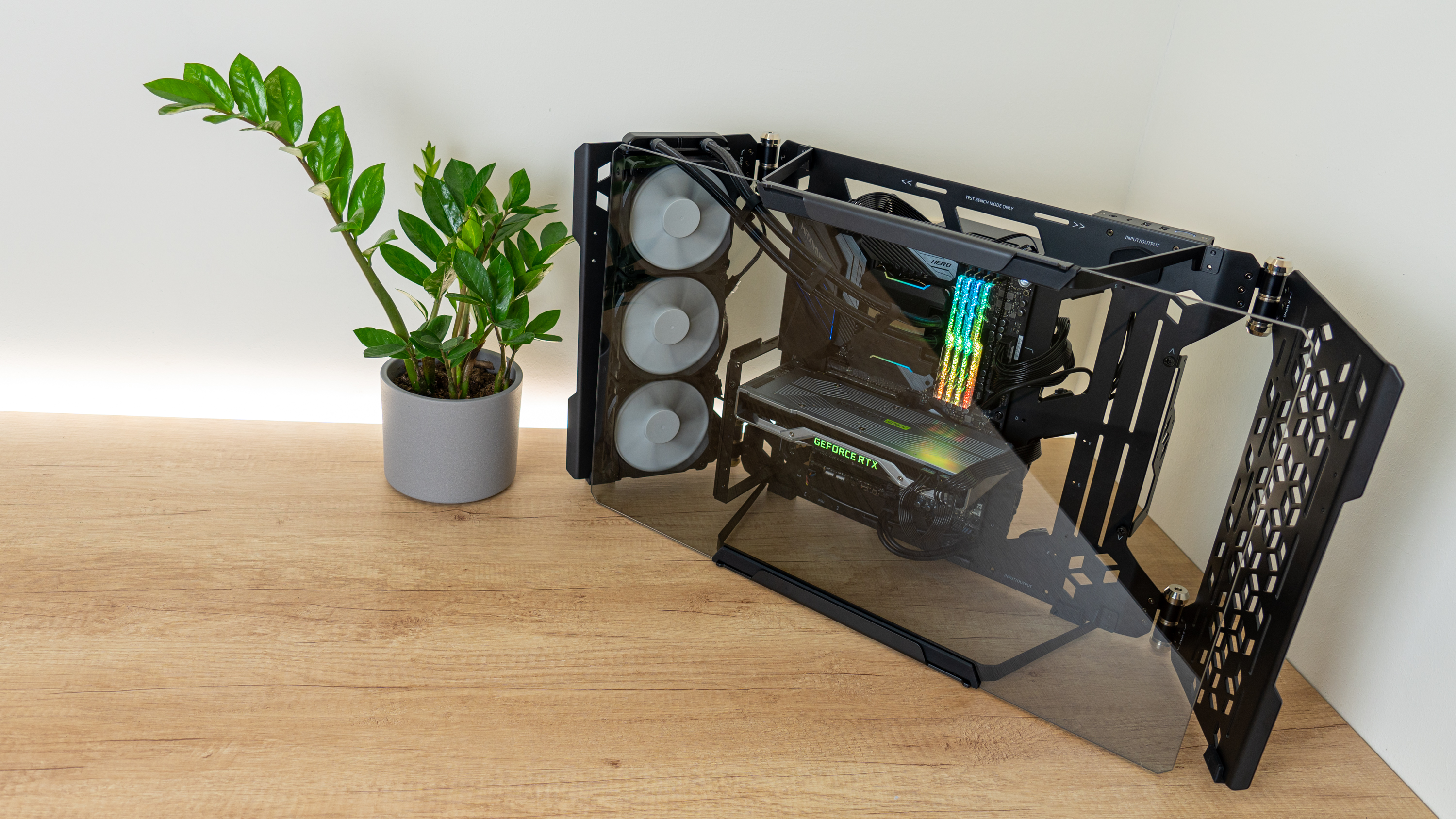
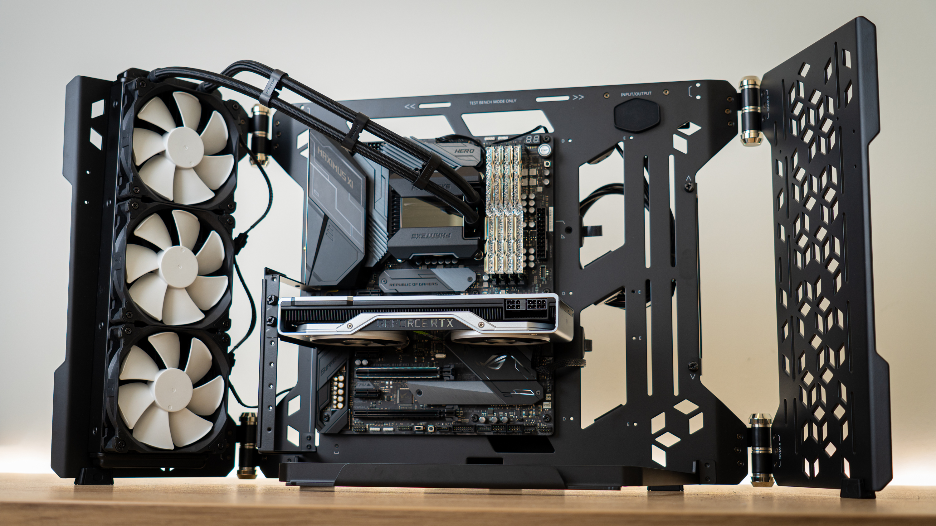
At this stage, the build is complete, so I powered it up for some pretty shots.
With as many things happening at the back of the chassis, a system in this case is best placed at the corner of a desk instead of at the side – so I did that and put the glass panel in place.
Of course, the chassis is capable of holding a lot more gear than on display today – you can chuck another radiator on the right wing, use a tube reservoir to the right of the motherboard, drop in multiple GPUs, etc. If you’re doing a custom loop, this chassis is a great foundation to build on. Just stick to soft-tubing as hard-tubing is a disaster waiting to happen with the swiveling radiator wings.
Current page: Hardware Installation
Prev Page Assembling the MasterFrame 700 Next Page Test Bench Mode & ConclusionNiels Broekhuijsen is a Contributing Writer for Tom's Hardware US. He reviews cases, water cooling and pc builds.
-
eichwana I love cases like this! I have a Thermaltake Core P5 and imo it looks amazing. It’s also really fun to build with, I can imagine with a nice secure hard tube loop, this too could look the businessReply -
pixelpusher220 Reply
Bottom of the first page describes it somewhat not I didn't follow it fully. Says if you want it flat you'll need to sacrifice some functionality. Or a really strong arm.timf79 said:I am not sure i missed it, but is there a way to mount/hang it on a wall?
