System Builder Marathon Q1 2015: $1750 Performance PC
Component Installation And Overclocking
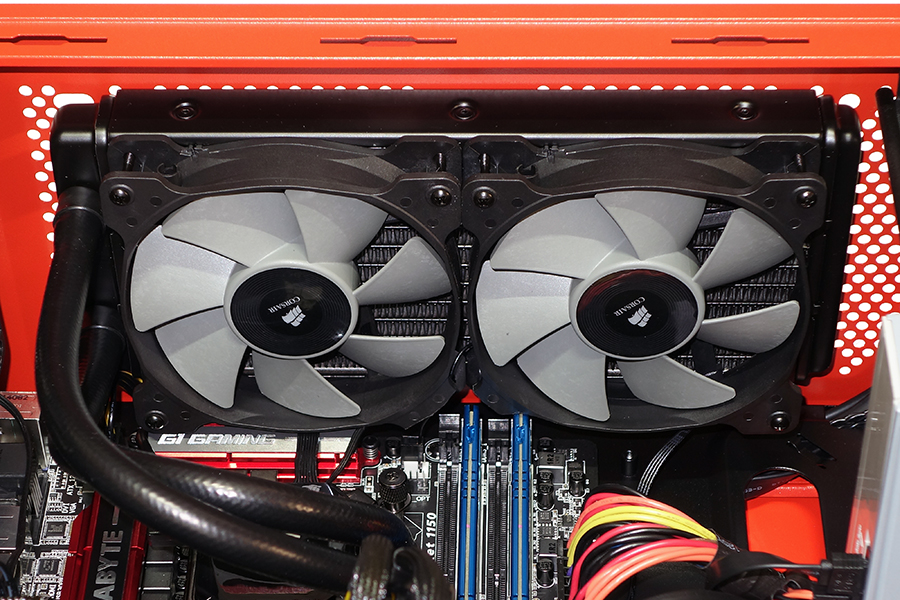
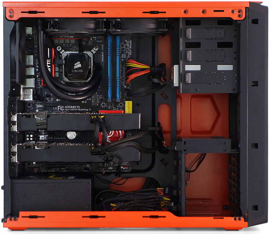
I stated on the previous page that Corsair’s Graphite 230T has limited space above the motherboard to install a radiator, but that I felt that the mounting hole offset provided by Corsair might offer enough clearance. My backup plan would have been to use alternative holes to add even more radiator offset. Unfortunately, none of that worked. Was it time to get out my drill and make holes of my own?
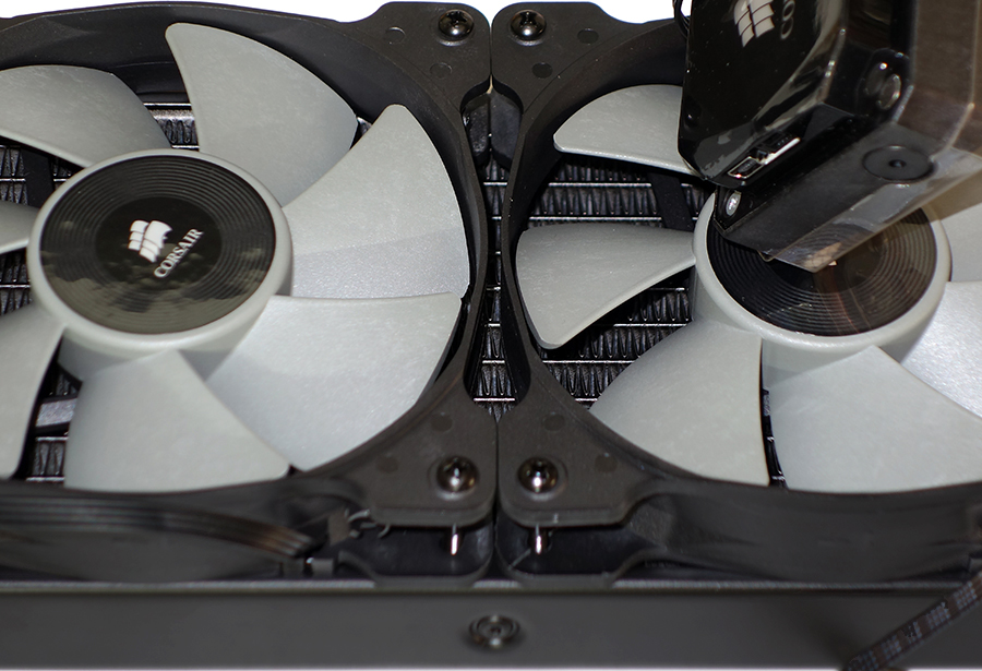
The little mark next to the forward mounting screw of the right fan is where it touched a DIMM. Unwilling to leave marks all over the outside of the case, I first asked myself “What Would Donny Do”, and immediately crossed that off my list.
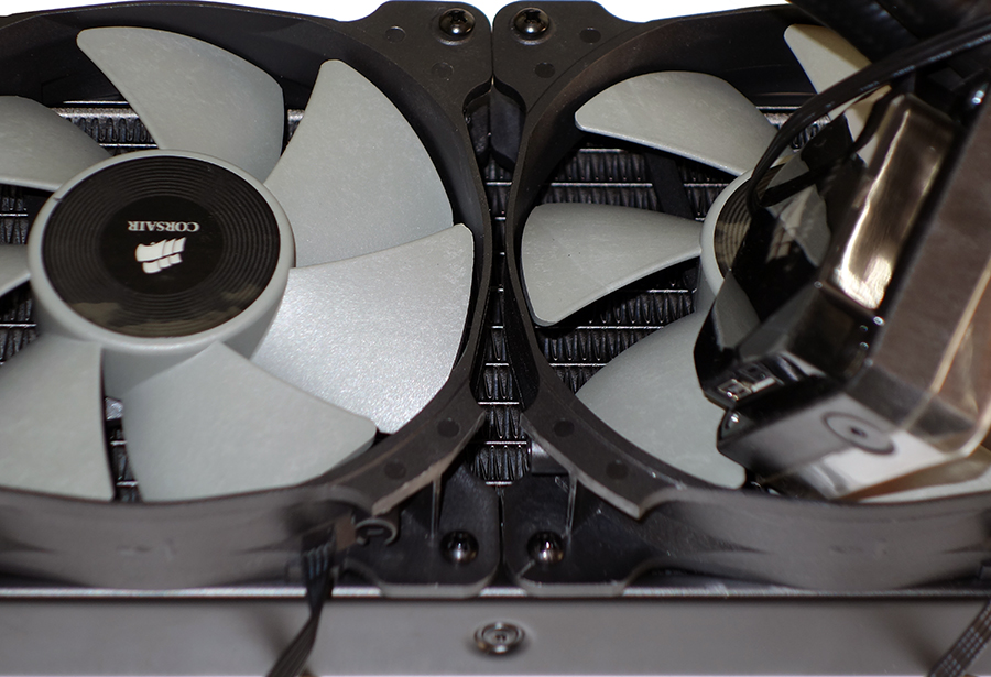
When it comes to nicknames like “Hacksaw”, there can be only one in an organization. So, I initially rounded off the outer corners of two fans using a bench grinder. After all, "Grinder" isn’t such a bad nickname, is it?
A little more test fitment revealed that it would be possible to use the case’s intended mounting holes, if only I removed a little more material. Sticking to the grinder theme, I used a die grinder to finish the work. Newegg sells alternative fans without the outer tabs for builders who have more money than talent.
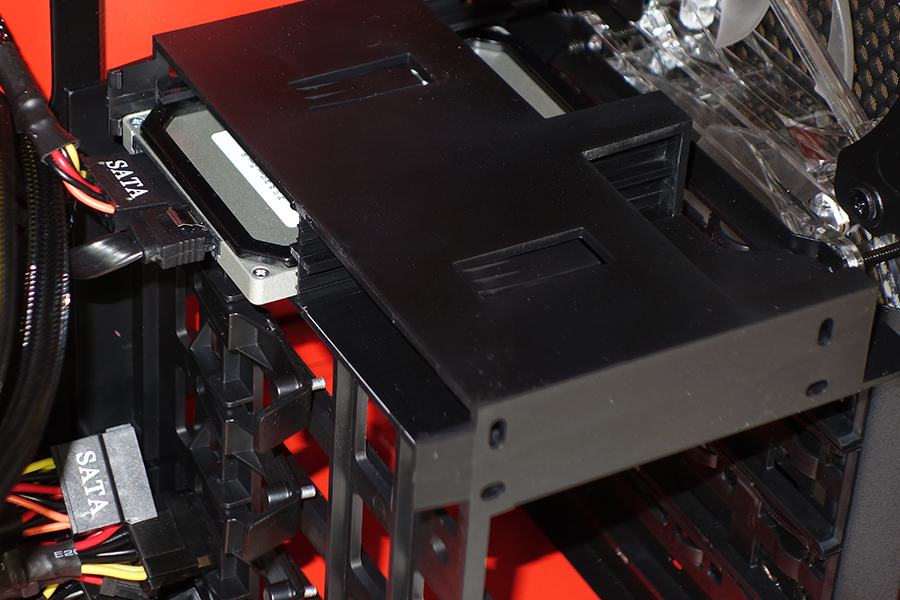
Corsair outfits the Graphite 230T with screw-free mounting options on all bays, though the height of its 2.5” bays left the MX100 SSD with excess wiggle room. Crucial’s included spacer took up the slack.
Everything else fit with room to spare and unrestricted airflow, in spite of the Graphite 230T’s low height. The case still has a hard time living up to its $80 price though, since it’s made from the same extremely thin and weak steel typically found in products selling for half as much. Corsair also left around an inch of extra space between the fan mounts and side panel hooks that could have been used for additional radiator offset, which would have enabled a completely straightforward installation.
Overclocking
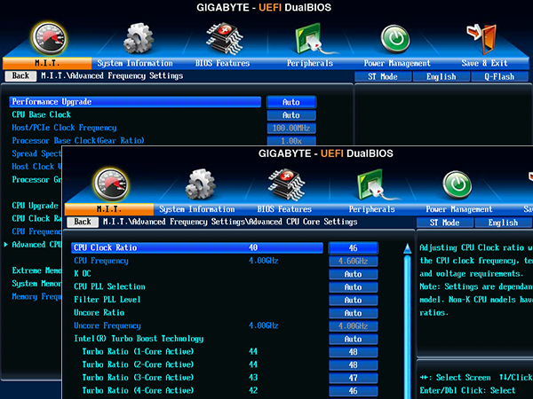
Starting out with Intel’s Core i7-4790K meant starting out with a processor that was already tweaked to higher peak voltage levels than we’d normally expect from a production Haswell-based die, and last time we were only able to get 4.6GHz (fixed frequency) out of this 4.4GHz-rated (variable frequency) part. Of course, that variation has something to do with limits, since the silicon supports higher speeds with greater stability under lightly-threaded loads. That gave me an idea.
Get Tom's Hardware's best news and in-depth reviews, straight to your inbox.
Rather than try shoot for a 4.6GHz fixed clock rate, why not mimic Intel’s Turbo Boost technology, but with a 400MHz increase? That would allow the system to run up to 4.8GHz in single-threaded tasks, and still give the system 4.6GHz of “punch” under more taxing loads.
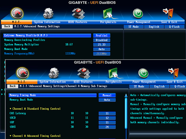
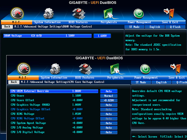
I had my fingers crossed for a good DRAM overclock, but it wasn’t in the cards (or the DIMMs for that matter). A mere bump to 2133MT/s required loose 11-12-11 timings for stability. Extra voltage didn’t really help much, and I just left it at 1.60V in frustration after trying everything to find a little more performance. As I recall, the same frequency and timings were stable at 1.54V.
CPU voltage, on the other hand, was very useful. A bump to 50mV over stock allowed the system to run stable at 4.8GHz fixed with all four cores fully occupied…at least until thermal throttling kicked in. That’s partly because it resulted in a 1.35V CPU core. I dropped to +20mV to compensate, and reverted to 4.6 to 4.8GHz, based on utilization. Our stability tests are extremely harsh, so you might think you can out-overclock me using this system. Our test breaks other people’s overclocks.
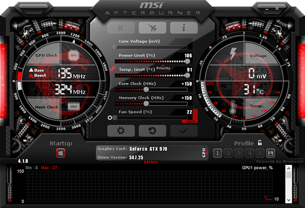
As with DRAM, graphics overclocking was an exercise in frustration. I’d spend up to two hours with a “stable” overclock, only to encounter a crash. While both cards initially appeared stable at +200MHz GPU and +300MHz graphics RAM, phantom crashes lead me to drop both settings to +150MHz.
Current page: Component Installation And Overclocking
Prev Page Memory, Drives, Case And Power Next Page Benchmark Performance-
dish_moose GTX 970 SLI - I cannot see how this would be a proper config given that the 970 VRAM is gimped over 3.5G. That being said with potentially that much gpu power, you would think this would make a great system - I've seen too many threads where hitting the 3.5G limit cause very bad stuttering.Reply
-Bruce -
Crashman Reply
Too many of which configurations? At this point I'd rather be running 5760x1080 than 4k, if that's where you're going.15379466 said:GTX 970 SLI - I cannot see how this would be a proper config given that the 970 VRAM is gimped over 3.5G. That being said with potentially that much gpu power, you would think this would make a great system - I've seen too many threads where hitting the 3.5G limit cause very bad stuttering.
-Bruce
This happens when I build based on reader feedback. Guess what? I ordered the day 5 bonus build in anticipation of these responses, even though the 3.5GB barrier wasn't known until after I placed my orders. Enjoy!
-
jezus53 I love that color scheme of the case. Reminds me of me my 73' Nova with the 350 small block painted black and Chevy orange. Makes me want to paint my case with the same theme...CURSE YOU TOM'S HARDWARE!!!!! I though I was done with my pc...Reply -
Onus My eyes!!!Reply
Actually, other than the case being an eyesore (IMHO, the high-end build should be at-home in a high-level corporate or engineering office), I might only grumble about the non-modular PSU. On a build like this, a larger data drive is a nit; such a machine could be intended for a networked environment and won't need it anyway.
This brings back a point I've brought up before. For this machine in particular, I think it is important to identify the user, and design a build that meets that person's needs, whether or not it necessarily wins benchmarks.
-
redgarl Multi-GPU without 4k benches is ridiculous. People are more likely to run at 4k than with three 1080p monitors.Reply
Also, 4k is a game by itself. AMD and Nvidia cards act really differently at UHD. -
Crashman Reply
Is that an offer? I'd LOVE to have a 4k display. I'm sure my colleagues would as well. PM me for the shipping addresses :)15379845 said:Multi-GPU without 4k benches is ridiculous. People are more likely to run at 4k than with three 1080p monitors.
Also, 4k is a game by itself. AMD and Nvidia cards act really differently at UHD.
-
Grognak Your own benchmarks showed that the 8GB versions of the R9 290X performed better than the 970 at higher resolutions, I know DX12 is coming with stacked memory and all but that's still the logical choice until Nvidia releases an 8GB 970.Reply -
Crashman Reply
Wait...you're blaming me for picking the cards? Did you even read the article? Your colleagues picked the cards in the previous SBM response thread :)15380062 said:Your own benchmarks showed that the 8GB versions of the R9 290X performed better than the 970 at higher resolutions, I know DX12 is coming with stacked memory and all but that's still the logical choice until Nvidia releases an 8GB 970.
Not sure about the higher resolutions situation though, since I only have a single 2560x1600 and a bunch of 1920x1080 displays. Given that 5760x1080 had already been determined as the limit, I think other readers chose fairly well!
-
cknobman So personally if I am building a high end machine like this it is going to be for 4k gaming.Reply
With that said I would have:
Ditched the k processor for a regular and used the box cooler.
Take the extra money and buy a storage HDD and faster RAM.
Also it would be really nice if on the high end builds we could get just a few 4k gaming benchmarks.

