Modifying An Asus A7V Motherboard For Duron-Overclocking
Tricky: Installation Of The SMD Components
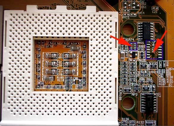
Now both the SMD components are added near the CPU socket. Apart from a soldering iron this work also requires a deflux pump and the appropriate flux. The picture below shows where to place both the components.
The SMD resistor (8 pins, 100 Ohms) must be inserted in position R16. The Logic-IC is placed in U42.
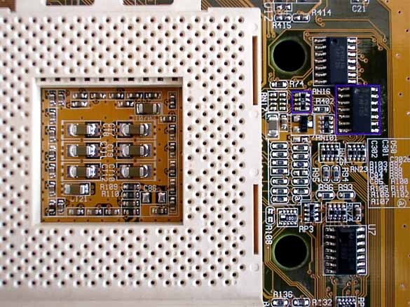
This is how the completely equipped circuit board (Asus A7V) looks like. Adding the R16 resistor requires working very carefully.
The installation of the very small resistor R16 (see picture further above) requires a miniature soldering iron and quite a steady hand. Otherwise it is very easy to accidentally solder the contacts that are very close together. We used a 150-ohm resistor on our test board because the appropriate part (with 100 ohms) was not available. In this case the CPU core voltage should be increased to 1.8 Volts, however, to guarantee stable operation. Installing the Logic-IC (74F125) was no problem at all: The task is accomplished quite easily with tweezers.
In principle the board is ready for operation once all the components are in place. But first the DIP settings must be adjusted. The table below lists all the multiplier variants for AMD's Duron and Thunderbird.
Get Tom's Hardware's best news and in-depth reviews, straight to your inbox.
Current page: Tricky: Installation Of The SMD Components
Prev Page In Depth: Modifying The Asus A7V Next Page DIP Switch Settings
