How (And Why) We Test USB Power Adapters
What Should We Expect?
In terms of output quality, I have no doubt we’ll witness the whole gamut, from horrible to decent. Moreover, I suspect most of our test subjects will be basic fly-back converters, with pennies separating their respective bills of material. Likely, they'll be differentiated mainly between those using a discrete two- to three-transistor oscillator and those using an integrated flyback controller-driver.
Since it takes very little extra care to design transformers capable of providing well over 2000VAC of isolation, and the other boundary-crossing components are typically rated in excess of 3000VAC, there shouldn’t be any excuse for component failures on the 1500VAC hipot test I plan to use. Clearance and creepage issues due to poor circuit layout is where I expect to find the worst safety disappointments, even though those are equally trivial to avoid with a little bit of cleverness.
As a teaser of things to come, let’s have a peek at what might be the cheapest adapter in my lot: one of those ubiquitous and usually dreadful Apple 5W charger knock-offs. I scored a colorful four-pack as sacrificial lambs for $6.

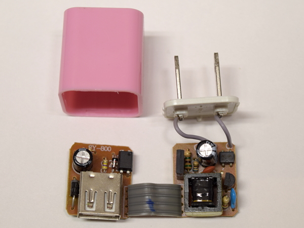
Here we have the innards of what I suspect is going to be a typical cube charger. From the top, we immediately see that it is one of those two-transistor oscillator designs using optoisolator feedback. There is one probable red flag in this picture: the optoisolator’s presence on the output board means that mains-referenced signals are going over the ribbon cable to the isolator. Given how tightly packed things are, there is an extremely high likelihood of clearance issues between mains and low voltage on this board.

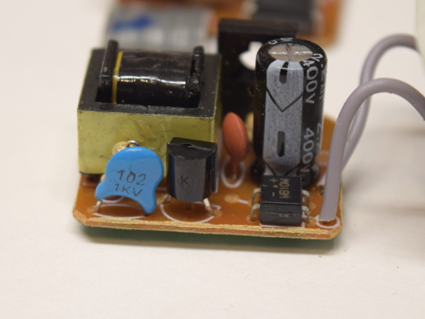
This adapter meets my expectations in the Y-class capacitor department by using a regular blue 1nF cap lacking any sort of safety approval marks or manufacturer brand. Should it ever fail, expect to see full AC line voltage appear between the output and ground if the non-polarized prong it is referenced to happens to be plugged in on the AC outlet's hot side. Yup, this is definitely shaping up to be one of those potential death-trap adapters.

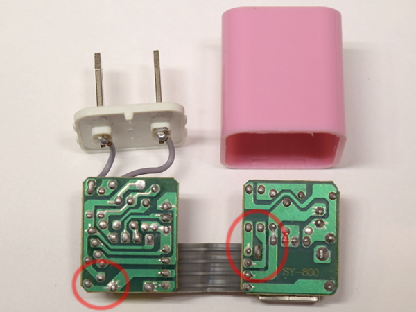
No, it does not get any better on the back: there is next to no separation on the mains board between the mains and low-voltage sides around the resistor pad. On the output board, separation between the optoisolator feedback traces referenced to mains voltage, the output voltage traces, and the USB connector shield are equally inadequate. At this point, there is no use in analyzing the design any further. This adapter's design clearly falls in the unsafe-to-use category. Only one safety-related question remains: what fails first?
No, that’s not a blue LED you see shining there. At approximately 1kV, an arc appeared between the optoisolator feedback trace and USB connector shield, 500V short of what I was looking for and possibly unpleasant (or worse) news for you if you happen to touch anything connected to the USB shield when such a fault occurs.
Get Tom's Hardware's best news and in-depth reviews, straight to your inbox.
Is this adapter a worst-case scenario? It does tick most of the “death trap” checkboxes I could think of up-front and verify via visual inspection. That leaves little room for other adapters to do much worse. We’ll have to see what the other adapters in my collection have in store. Also, I’m far from done exploring this one's issues. It may very well have more unpleasant surprises for us to uncover.
In this case, exceeding my expectations for the worst is actually a good thing. I would have felt a little cheated if adapters I had purposely purchased to showcase one of the worst designs possible exceeded my expectations in the opposite direction. Will this turn into a horror show? Time will tell.
MORE: Best Deals
MORE: Apple 5W Adapter Knock-offs: The Colorful A1265 Tear-Down
-
eenoram Love the article but the embedded videos arn't working across 4 different up to date browsers running with or without adblocker. Bummer!Reply -
berezini looks like toms doesn't have anything else to write about so they re-write old articles a month or two old to the same conclusion.Reply -
Daniel Sauvageau Reply
The A1265 look-alike story from last month was meant to come out after this one but due to some scheduling weirdness, they got swapped and as I wrote in comments to the "first" story, the set of fake A1265s used for the first tear-down (and also to demonstrate the point of this series which was intended to start with "how we test"), there will be a bunch more to come in the future. The ending was intended to be a teaser (and somewhat of a spoiler) for the first tear-down, which is why my preview here stopped at the first failure. In the actual tear-down, I cleared each successive failure until the adapter was either dead, destroyed or what remained of it passed isolation withstand.20619893 said:looks like toms doesn't have anything else to write about so they re-write old articles a month or two old to the same conclusion. -
bit_user Thanks again, mate. Looking forward to some good recommendations.Reply
How can we help fund your efforts? If your recommendations save me even one expensive equipment failure, it'd be worth a lot. -
bit_user Reply
So you read all the CES coverage? I still have some bookmarks to check out, as I couldn't keep up with it.20619893 said:looks like toms doesn't have anything else to write about
IMO, it's understandable if they & the industry are having a bit of a quiet week (meltdown/specter aside), after CES. Most companies with anything to announce did it at CES, so the newswire is definitely going to be quieter this week. -
Daniel Sauvageau Reply
Recommendations-wise, I have one coming 2-3 stories from now which I sent in for editing last week and costs ~$10 and passed all of the tests I threw at it. It did have one potential manufacturing-related safety flaw in it but I'd need multiple samples to determine whether I got unlucky or should flag it as a significant concern.20621006 said:Thanks again, mate. Looking forward to some good recommendations.
How can we help fund your efforts? If your recommendations save me even one expensive equipment failure, it'd be worth a lot.
As for how to contribute, I'm open to suggestions if there is enough interest in doing so. -
chaz_music Something you should add to this: I have noticed many AC adapters being sold on Newegg, Amazon, and eBay that don't have a UL or ETL mark. That means that they did not go through either those agency's safety testing and analysis. Many of the things you found would be caught by UL, especially the shock and fire issues.Reply -
Daniel Sauvageau Reply
Marks are only as trustworthy as the supply chain between the buyer and manufacturer is. You can't trust any marks on stuff from generic off-shore sellers who have no domestic liability as the seller has very little incentive to ensure that marks on items are genuine. By the time people realize that they got a fake or fraudulent item (that looked and behaved roughly like the real thing), the feedback period on the sale is often expired and the original listing long gone.20622599 said:Something you should add to this: I have noticed many AC adapters being sold on Newegg, Amazon, and eBay that don't have a UL or ETL mark.
The first line of defense against no marks and fake marks is buying from a domestic source where liability falls onto the vendor/importer when the manufacturer is out of legal reach.