How (And Why) We Test USB Power Adapters
Some Equipment Required
All of these tests can be performed with relatively affordable and readily available equipment. The process can be made much simpler, faster, and safer with specialized equipment, though. Since I don't have much of that stuff on-hand, I'll be relying on a mix of home-built gear and adapted off-the-shelf hardware.
What do I need, exactly? In an ideal world, I would have the following:
- A variac to apply different input voltages
- A high voltage AC source for hipot testing
- A power meter to measure the adapters’ input power for standby consumption and efficiency
- A high-voltage meter
- An adjustable DC load for applying load to adapters
- A USB test cable rigged for measurement
- An oscilloscope to check the adapters’ output and response to load changes
- A good ground for safety reasons
- An isolation transformer
- A blast containment chamber
- Maybe a camera to catch catastrophic adapter failures as they happen
What do I have on-hand? Well, before you read any further, allow me to suggest you don't try any of the equipment substitutions I am about to show you at home. I’m setting up these rigs and doing these tests so you don’t have to. Consider yourselves warned.
Variac
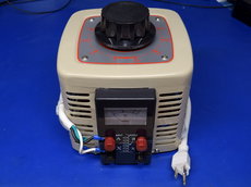
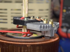
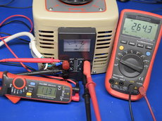
My newest piece of test equipment is a variable AC transformer, or variac for short, procured primarily for this project. These heavy devices consist of a single-layer toroidal transformer, a stripped and flattened area along the transformer’s top, forming an exposed contact area, and a graphite or similar wiper contact that moves across the exposed copper winding to select the output voltage. They come in a variety of input-output ranges and current ratings, handy for any application where an input voltage needs to be stepped up or down by some variable amount, such as compensating for low or excessive line voltage, tweaking the output of another transformer connected to the variac’s output, or providing variable inductive ballast. Whereas small commercial variacs often have a hard-wired cord and built-in outlets, industrial versions come either with binding posts for convenient wiring in unconventional manners or as raw open-frame units (no chassis) for integration in custom control panels or burial into automation cabinets. Today, I'm using my 2kVA, 110V-in/0-250V-out variac to both check whether “universal” adapters are truly universal by sweeping their input voltage from 90V to 250V, and also to tweak my high-voltage transformer’s output (see below) for hipot testing.
High Voltage Transformer
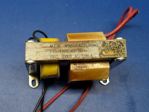
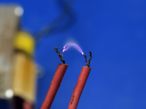
High voltage is very handy in electrical testing. It's useful for checking wire, circuit boards, transformer winding insulation, and safety-rated (X/Y) capacitors for cracks, holes, cuts, pinches, mechanical shock, and clearance issues, or latent damage that cannot be detected any other way.
When people think of high voltage in a consumer setting, they often mention the transformer driving a microwave oven's magnetron. As readily accessible as that'd be, it would be far too over-powered and potentially deadly to keep near my bench. Instead, I went with an old oil furnace arc ignition transformer able to deliver up to 3500VAC and 10mA when fed 120VAC. That's still plenty to impart electric arc burns, but it's otherwise harmless to healthy humans.
Using the variac to adjust the input voltage, I can get any output I want from 0VAC all the way to 4200VAC before my HV transformer saturates, buzzing increasingly loudly to let me know. This is the perfect range to cover hipot testing, from the most lax standards at 1kVPk all the way to medical-grade isolation transformers at 4kVAC.
Get Tom's Hardware's best news and in-depth reviews, straight to your inbox.
Oscilloscope
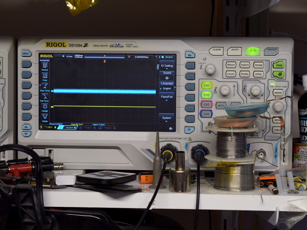
While multimeters may be adequate for many troubleshooting and measurement tasks, they lose their usefulness when dealing with signals that vary over time faster than what they can display. Even on a fast meter, human eyes and brains would have a hard time making sense of more than a handful of numerical values per second. That’s when an oscilloscope becomes a useful tool to plot voltage against time at scales from seconds, to see slow-moving trends, to picoseconds, for troubleshooting today’s ultra-fast serial protocols and microwave signal analysis.
Prices range anywhere from about $100 for generic pocket models to millions of dollars for state-of-the-art multi-channel systems with input bandwidth in excess of 40 GHz. While far from a luxury, Rigol’s $400 DS1054Z is a great value-oriented scope if you can tolerate its many quirks and shortcomings: the probes’ needle tips under the hook attachment tend to rip off the probe bodies when removing the hook attachment, the 1x/10x probes only work reliably in 10x mode, auto-calibration does not correctly calibrate out the channels’ zero, channels’ zero shift about depending on what combination of channels are enabled, and on-screen text entry defaults to Chinese every time the scope is rebooted. Thankfully, none of those issues really get in the way of observing signals, and in cases where higher accuracy is required, dumping waveform memory to a file and pasting it into a spreadsheet to apply corrections before doing some more mathematical wizardry on it is an option I have exercised many times before.
High-Voltage Meter
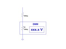
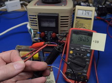
If you thought I was heading into mad scientist territory after discussing the HV transformer, it gets more interesting. As you may have guessed, a high-voltage meter is simply a voltage meter for measuring higher voltages. When you do not have such a thing on-hand, you can make one by creating a voltage divider between whatever you want to measure and an ordinary multimeter.
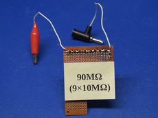
Most multi-meters have a 10MΩ input resistance on the voltage range, which means that you can form a 10:1 voltage divider by adding 90MΩ in series, for a total of 100MΩ, which is exactly what I did using nine 1210-size 10MΩ resistors. Doesn’t an open-air 5kV voltage divider look delightfully hazardous? Of course, the perforated board is only temporary. Once I get proper PCBs made, I will shrink-wrap it for some added safety. As you can tell from the third slide, though, I’m not letting safety get in the way of some single-handed HV fun. On the last picture, I’m feeding 170V into the HV transformer to get an arc-striking voltage of about 5kV, which gets dragged down to about 1800V once the arc is struck.
I really should get some long shrink tubing to sleeve the HV cables. Throbbing from the electric field when touching them at 3kV and up makes me a little nervous.
DC Load
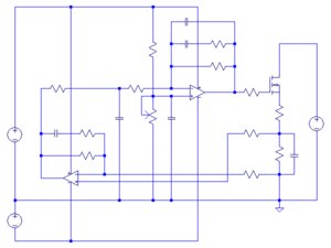
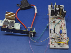
Testing power supplies requires loads to hook up, allowing us to observe how they behave and analyze their output quality. I don’t have one of those yet, so I cobbled together a basic prototype from parts I had lying around. In the past, I used a simple shunt voltage regulator based on a 431 shunt regulator (often called programmable zener diodes because, just like zener diodes, shunt regulators attempt to achieve regulation by pulling increasingly high current once their threshold voltage is exceeded) and periodically tweaked the divider potentiometer to keep the current relatively constant. That worked well enough for outputs with nearly constant voltage, where I only had my shunt’s thermal drift to worry about.
For my Getihu power bank’s direct cell discharge test, where cell voltage was changing throughout the discharge cycle, I needed a more proper constant-current load with a current sense resistor, a sense amplifier, and error integrator. An even better implementation would have a separate error amplifier between sense output and integrator input for better control over how the integrator responds to reference value changes. Since my current circuit cannot do fast transients (and won’t be able to unless I get around to tacking a micro-controller on top of it), I’ll be going low-tech with a pair of 10Ω resistors in parallel for those. Yes, that’s another project I really should make a PCB for to reduce the amount of noise pickup from long component leads, lack of ground plane, and breadboard randomness.
USB Cable
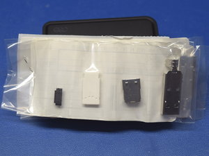
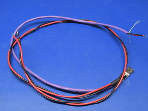
Off-the-shelf cables have thin-gauge wires (typically #20-22 for the higher-quality ones) and don’t allow access to voltage at the connector, meaning that any voltage measured at the end of a typical cable will have a significant cable loss component to it. Instead of using a pre-made cable, I went with a raw connector fitted with one cable dedicated to remote measurement and two #16 wires for load.
Why go so seemingly far into overkill? Past experience in last year's automotive USB adapter round-up taught me that some adapters are (unintentionally?) capable of delivering scary amounts of current before they shut down, especially in the seconds following a cold-start. With #16 wires, I shouldn’t need to worry about melting down my cables, though connectors may be a different story.
Power Meter
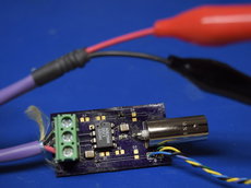
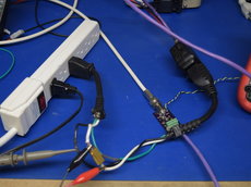
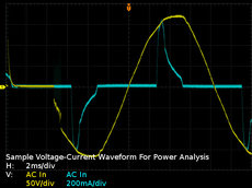
Measuring input power is always handy for calculating how much devices cost to operate, how much they cost to leave plugged in while not in use, and how efficient they are. More advanced power analysis can be used to measure apparent power, power factor, inrush current, and harmonic distortion, which may fly over most folks' heads, but are still relevant for power quality analysis and conducted electromagnetic radiation purposes on the utility power distribution side of things. Since I do not own a proper power meter, and Kill-a-Watt-style meters lack the resolution I require for sub-watt standby measurements, this is another area where I went down the DIY path for capturing input voltage and current waveforms, dumping the scope’s waveform memory into a file, importing the file into a spreadsheet, and number-crunching my way through many of the same measurements a $2000+ dedicated power analyzer can provide, albeit with a greater error margin.
How does this setup work? I get my voltage the obvious way by tapping into the live line with a probe set on 10x and measuring current on the neutral side using a 0.1Ω 10W metal film resistor, leveraging an AD629 high-accuracy, semi-isolated current-sensing amplifier to get the cleanest current waveform I can manage. Why sense on the low side? The amplifier only guarantees 60dB of common-mode rejection, meaning that I can expect approximately 0.1% of the inputs’ common-mode voltage to show up at the output. If I sensed on the live side, I could have as much as 0.1% of 120VAC (0.12VAC) superposed on my sense output, which I’d need to characterize and correct for. By sensing on the low side, this common-mode noise source drops below 100µV and gets lost in my oscilloscope’s noise floor where I don’t need to worry about it.
Beefy Ground
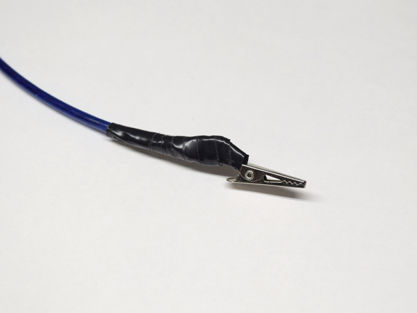
Since I will be messing around with some AC adapters of questionable quality, I am getting into this expecting at least a few of them to fail in dangerous ways. One of those ways is isolation failure between AC mains and output, hence my intention to test their isolation to at least 1.5kVAC. To protect myself and my equipment from such a failure, I’ll be using a #12 gauge ground cable tied directly to the nearest junction box to ground the USB adapters’ shield and negative. Should there be an isolation failure from live to output, it will hopefully blow the fault clear within the USB AC adapter or trip the breaker without damaging my equipment or shocking me.
Isolation Transformer
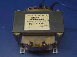
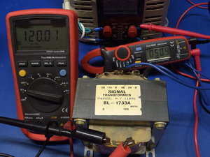
An isolation transformer is used to separate or “float” a load from ground-referenced mains. There are multiple possible reasons to isolate devices from mains. One of the most common is for breaking ground loops to reduce common-mode noise between components. Another is to have a floating or isolated AC source to power devices without having to worry about fault currents going to ground, or for poking around circuits with a non-isolated oscilloscope probe. Any regular transformer with adequate ratings can be used for isolation, as they aren’t directional. But proper isolation transformers may have additional insulation for increased safety margins and guard windings to reduce leakage current between windings. I don’t have a fancy dedicated isolation transformer on-hand, but I do have a variac that allows me to have almost any AC voltage I want from 0V to 260V at up to 8A and a ~400VA transformer with an 8A/48V winding. By feeding 51VAC from the variac into the 48VAC winding now acting as my primary, I get the isolated 120VAC I need on the 120V winding acting as my secondary.
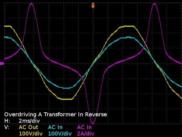
One caveat of doing this is that the magnetic core is rarely sized to accommodate much more magnetic flux than the voltage and current it is rated at require. In this particular case, the magnetizing (no load) current at 120V output was a reasonable 650mA. But as I dialed the input voltage up to see if I could reach 240V, the magnetizing current reached 6A by 200V, a tell-tale sign (along with loud buzzing and vibrations) that the transformer was well into magnetic saturation. Comparing AC input to AC output voltages reveals some extra inflections after zero-crossings and sharper drop-offs after peaks, courtesy of harmonic current from clipped peaks.
The current waveform, on the other hand, is far less subtle about revealing the transformer’s discomfort: under normal operation, an unloaded transformer behaves like a very large inductor, and the current waveform of a mostly sinusoidal voltage applied to a large inductor should be a distinctly sinusoidal waveform phase-shifted by 90°. Here, the current waveform is clearly dominated by harmonics and those start showing up much earlier (around the 100V mark), long before output voltage deformation becomes noticeable at 140V and obvious by 170V.
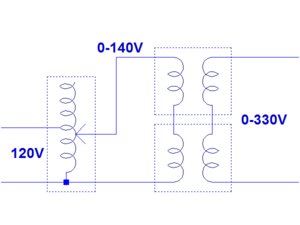
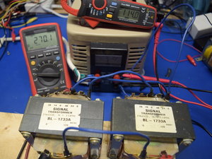
Fortunately, I happen to have two of these transformers, which means I can dodge the single-transformer limitations by wiring them in series to double both the usable input and output voltage ranges. If each transformer can give me 135V out from 57V going in with minimal distortion, two of them in series get me 270V out from a 114V input. Isolation-wise, both transformers passed at 2kVAC, so no worries there.
Blast Containment Chamber
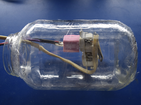
Be it on their own initiative or with a helping hand, I do expect some of these adapters to actually explode (mainly in the form of electrolytic capacitors blowing their cases off), or at least catch on fire. We'll need something to contain most of that mess. Reporting in for duty as a low-energy blast containment vessel is a club-sized pickled banana pepper jar with two layers of cling-wrap to catch glass shrapnel in case of explosions large enough to shatter it. Should the jar break, I may end up building an MDF box with a polycarbonate window.
While the adapter is shown with its pink birthday suit still present, I'm more concerned about catastrophic failures after I break adapters open and need to do more live-testing on them, in which case the original shell won’t be there to contain failures.
MORE: Best Deals
MORE: Apple 5W Adapter Knock-offs: The Colorful A1265 Tear-Down