ABCSell AR-18 USB Power Adapter Tear-Down: Another Death Trap
Naked Secondary
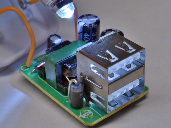
Do we at least get double insulation on the secondary? As you may have assumed after seeing the price, the answer is an all too predictable no.
Since I have yet to see a transformer without double insulation pass my isolation withstand test, I have no reason to believe this transformer will fare any better.
Who Left Out The Lights?
While the USB ports feature slightly diffuse transparent plastic components, and the LED footprints on both sides (bottom corner) clearly indicate that these were meant to be illuminated, the LEDs themselves were omitted from this variant. Considering that the contact support structure for the ports is surrounded by a metal shield (except on the back), the LED footprints’ locations do not make much sense.
In the unlikely event that this adapter survives my testing, I may add LEDs to see how they look.
Board Bottom
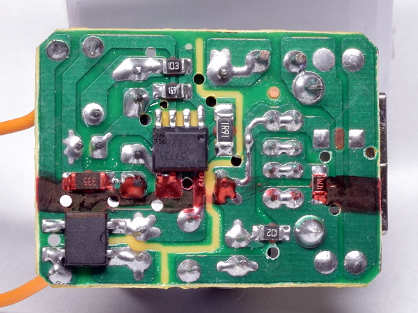
On the bottom, we find an attempt at separating the primary side from the output by removing some of the solder mask along the boundary, a diode bridge, a 330kΩ bootstrap resistor for the ND5773, a 1.9Ω primary-side current-sensing resistor, and miscellaneous other resistors. I had no luck finding datasheets for the ND5773, meaning it's likely a custom-marked chip.
Separation between primary and secondary appears to be at least one whole millimeter, which makes it double that of the A1265 look-alikes. This is better, but still not good enough.
Charger ID
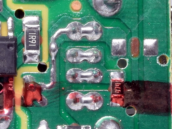
What differences are there between the 2.1A “iPad” port and the 1A port? None. The two ports’ +5V pins (first horizontal pair at the top) are tied together, both ports’ D+ and D- pins are tied together in the middle, sharing a single 470kΩ resistor to ground, and both of their ground pins are tied together at the bottom.
Get Tom's Hardware's best news and in-depth reviews, straight to your inbox.
While the soldering quality looks generally decent, there are tiny solder beads all over the place, one of the largest painted over in red marker left from the middle.
In case you are wondering, the unpopulated footprint to the right is for the omitted LEDs’ current-limiting resistor.
Standby Power
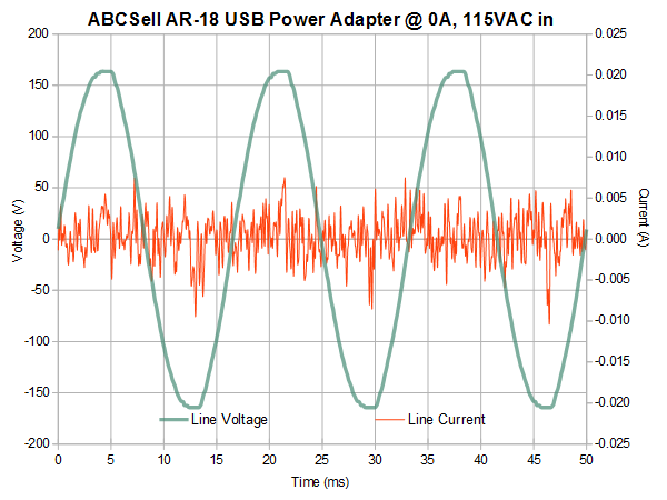
At 115V AC input, the AR-18’s standby power barely registers above my measurement's noise floor at 27mW, dropping to an even lower 14mW under 230V input. I had to check that my sense amplifier was actually turned on and repeat the measurement a few times to convince myself that this was actually real.
With noise accounting for most of my signal, I have no real accuracy on those two readings. Since there is a 1kΩ bleed resistor on the output, the absolute minimum possible power consumption is 25mW.
Efficiency
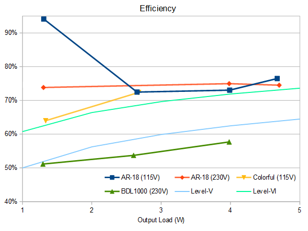
Results under load confirm that the AR-18 is actually capable of decent efficiency by beating Level VI requirements, which is exactly what I would expect from an adapter based on a monolithic flyback controller. Far less impressive is that the AR-18 only manages 960mA of output current on 115V input before its output trails off below 4.75V, making it a 1A output adapter at best.
Output Noise Waveform
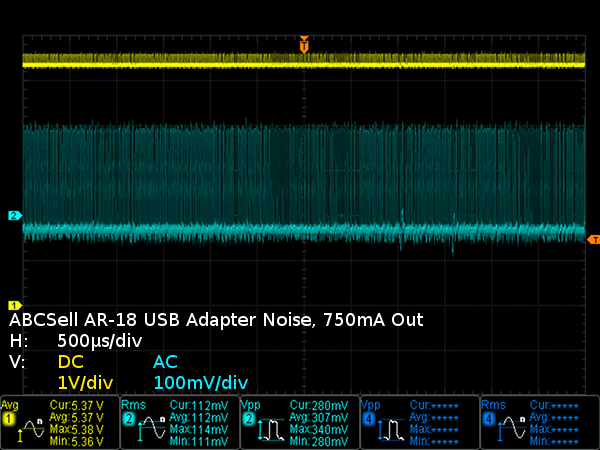
What happens when you take a flyback converter and give it only one ordinary electrolytic output capacitor for output filtering? You get a wall of switching transients dominating the noise landscape. Thankfully, this is much better than usual for cheap adapters, as you’ll see when I bring in some past results for comparison.
Peak-to-Peak Output Noise
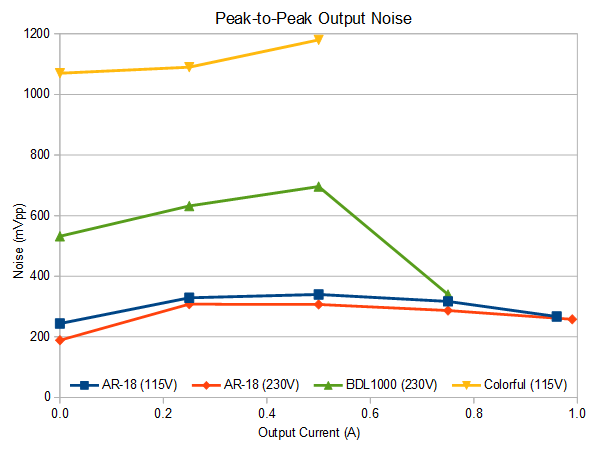
Where peak-to-peak noise is concerned, the AR-18 fares considerably better than its ~$3 competition. I’m going to guess that a large chunk of this is due to its single-board construction significantly shortening the distance between the transformer, output diode, and output capacitor.
RMS Output Noise
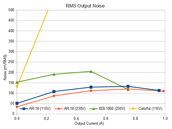
The AR-18 easily outperforms its competition in the RMS department thanks to a monolithic flyback regulator doing a far better job of regulating output voltage against ripples across its under-sized input capacitor than the other adapters’ simple two-transistor oscillator circuits.
Output Voltage Regulation
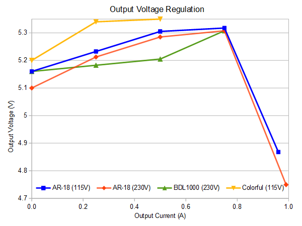
From how the AR-18’s controller raises its output voltage with load, we believe that it provides up to about 150mV of cable drop compensation. No problem; cable losses will easily knock that 5.3V maximum down to less than 5.25V.
-
dudmont Sauvageau, you've got a touch Doc Brown in you, don't you? "Now where am I going to find that 1.21 gigawatts?....."Reply -
chaz_music For me, the picture of the housing bottom side (plug view) is all that is needed. It does not have a UL or ETL mark on it. These are safety agency marks that certify that the device won't kill you. :)Reply
For Europe, you would also have a CE mark. I have found many power supply products in the past few years without UL or ETL on them. I won't use them if those marks are not there. That is because I am an engineer who has to make products that meet UL/ETL and CE. The requirements to meet these agency tests check for exactly the same thing that you showed in your tear down. And you did a great job!
Anything that connects to the utility or mains should have safety marks for your country.
- Charles -
wuethrichtech idk, i understand things in this world almost well enough to do tear downs like this...which is why i find myself torn. All the saftey features we would require if it were made here are left out and millions of these must be all around the world... where are the deaths? where are the fires that were not caught in time?Reply
yet having a decent understanding, If this sorta crap not only snuck by but was tolarted and produced here...id be extra woried about living in an apt where joe schmo the window licker is going to put one of these in every room and thinks he can rebuild his ebike battery with a pile of 18650s10w soldering iron and no bms -
Daniel Sauvageau Reply
If the adapter is the only thing nearby, it'll burn out, leave a scorched wall outlet and dry-wall, probably go unreported. If there are tons of things nearby and many of them are possible causes, then the fire will burn all of them beyond recognition and the exact cause may be left undetermined.20927821 said:All the saftey features we would require if it were made here are left out and millions of these must be all around the world... where are the deaths? where are the fires that were not caught in time?
For deaths by electrocution to occur, the user needs to provide a relatively low impedance to ground, which usually isn't the case when people are on dry ground and their phone is the only thing they are touching. Even a shock from 240Vac while wet and grounded isn't a guaranteed death, it'll definitely be painful well beyond anything that could be considered acceptable exposure. If you look for non-lethal shock reports, those are plentiful. Any of those could turn lethal under more unfortunate circumstances.
When all it takes to make things significantly safer is a tiny bit more care in the board layout, sufficiently wide insulation tape between transformer layers and some sleeving at least on the secondary, there really is no excuse for these death-trap grade adapters to exist. These things are accidents waiting to happen, only a matter of when and what the circumstances will be when they do. -
jdog2pt0 Could spend your whole life tearing apart this cheap crap, and if you like electronics tear downs (especially unsafe ones) check out Bigclive on youtube. Otherwise, my rule of thumb when buying chargers and the like is to....buy Anker and be done with it.Reply -
gasaraki Why don't you tear apart a name brand non-apple charger for once? Like an Anker Quick-charger or something. Or show us a name brand Samsung or LG charger. Tearing apart no name chargers are well and good but no one is going to buy those crap.Reply -
Daniel Sauvageau Reply
I've had at least three of those: SilverStone UC01, Aukey PA-U32, Philips SPS8038, four if you count the PrimeCabkes/iKits charging station / device organizer which is also miles ahead of generic adapters.20930057 said:Why don't you tear apart a name brand non-apple charger for once?
As for "nobody would buy those", I'm pretty much certain millions of these dangerous adapters are bought by unwary people every year, hence the importance of promoting awareness of how unsafe they can be. Both of my sisters have a couple "dollar store specials" which I'm planning to trade them for as I find adapters that meet my grade.
At the moment, Aukey's PA-U32 is at the top of my list, as does another device from a new name in this category, albeit after modding to fix what looks like an unfortunate design flaw in what otherwise appears to be a top-notch adapter. You'll see that last one in late-May.
As for seeing more Aukey or some Anker, Roger got me a pair of each. The first one's tear-down will likely be out in June. I meant to start working on it while dog-sitting at my sister's home but forgot to bring my other adapters, so that's on hold until the next time I drop by my apartment later this week. -
tproveau I have a two usb out 2.4A each outlet 4.8A total power adapter made by Ubiolabs that is a very big seller since it retails at Costco in the US. It is UL listed I.T.E. power supply, FCC and RoHS compliant. Model # is CHG1003 B/N 110116HJT. Input 100-240 volt~50/60Hz 0.7A. My question is it looks to be a safe unit considering the label but is it? The package comes with two five foot long USB to micro USB cables and sells for eight bucks. Why buy the unknown stuff from China when you can get this package locally so inexpensive? Also being so inexpensive is it up to what it appears to be?Reply
Thanks

