CyberPower EC350G UPS Tear-Down
Get Tom's Hardware's best news and in-depth reviews, straight to your inbox.
You are now subscribed
Your newsletter sign-up was successful
Reverse-Engineering The Supply
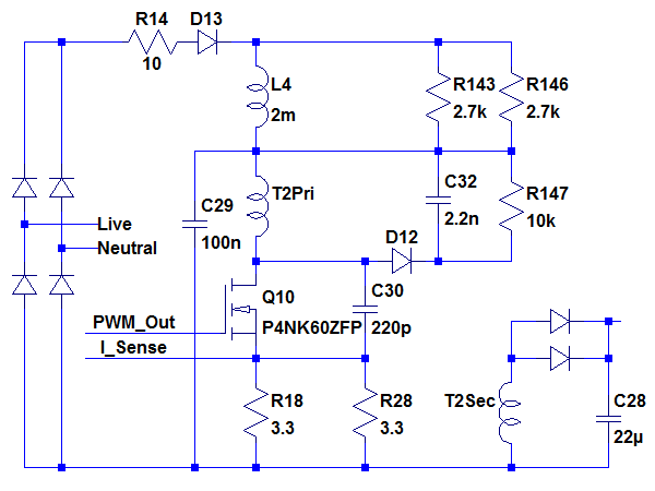
This makes more sense, at least to me: instead of using a bulk input filter capacitor like most power supply circuits, the circuit uses a current-fed topology where input energy gets stored in L4. The more power that gets delivered to the output, the higher the current through T2’s primary and the more energy gets stored in L4’s magnetic field to boost voltage on C29 for the next cycle.
While many UPSes warn that there may not be isolation between battery negative and AC input, models with user-accessible batteries are usually isolated anyway. In this case, both sides are clearly tied to rectified AC negative. Since you need to remove the rear cover and expose the main PCB to access the battery, live battery swaps are clearly not a good idea regardless of feasibility.
Beefed Up
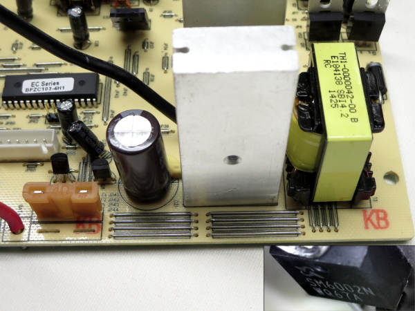
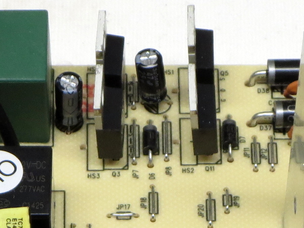
On top of the heavily tinned track on the bottom, the battery positive path from the fuse and 2200 µF Su’scon capacitor to the transformer’s primary center-tap gets beefed up with three sections of four jumpers each. Each of the transformer’s two primary halves gets driven by one 60 V/80 A/9.8 mΩ Sinopower SM6002M FET, each on its own towering aluminum chunk. Under full 350 VA load, each FET dissipates about 4 W, which won’t be enough to warm these blocks up by much before the tiny battery runs out. A 650 VA model with a 6 Ah battery might be a different story if the component complement remains exactly the same.
Output Bridge
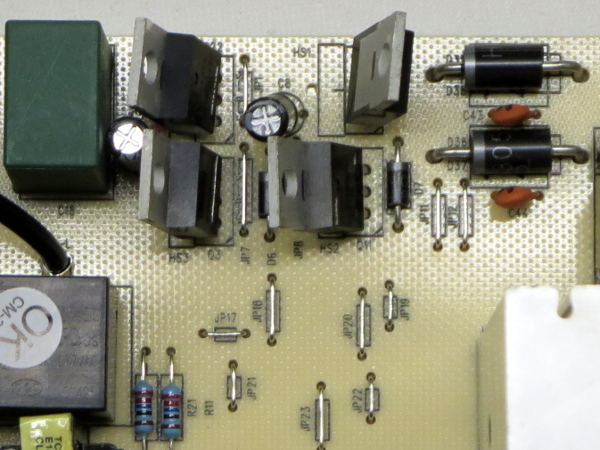
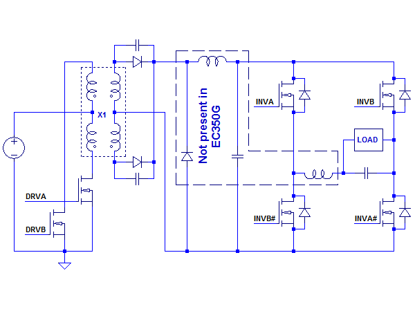
A pair of opto-isolators and related support components on the bottom drive the output bridge’s two 200 V/18 A/0.15 Ω International Rectifier IFR640N pairs, with the high side fed directly from the step-up transformer’s center-tapped secondary through a pair of 400 V/3 A HER305 diodes with no filtering on the input. There is no filter inductor between the bridge and 470 nF output X1-class capacitor either.
I wrote it before but I’ll write it again: I’m no fan of TO-220s getting bent over and looking like a shorting hazard. Silly little heat sinks like the ones found in APC’s BGE90M’s output bridge would help secure those FETs.
What's There And What's Not
The EC350G trades the parts cost of a full bridge rectifier for the copper and transformer core size cost of a center-tapped secondary. Then, the rectified HVDC gets switched through to the output by the dangling FET bridge. I am expecting to see a lot of whatever it is the HVDC converter puts out to appear directly in the on-battery waveforms.
One Size Fits (Almost) All
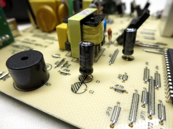
I quit looking for capacitor brands other than Su’scon after finding the tenth one. Unlike past CyberPower units that featured a mix of manufacturers, the EC350G is fitted exclusively with Su’scon electrolytics. Most of them are 50 V 22 µF, the two used for the bridge’s high-side drivers are 25 V 47 µF, and there is one 2200 µF 16 V across the battery voltage. While designing products to minimize the number of different components reduces the risk of accidental and potentially catastrophic substitutions, it also trades some efficiency and cost for manufacturing convenience.
Get Tom's Hardware's best news and in-depth reviews, straight to your inbox.
Standby Power
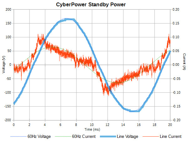
The standby current waveform looks pretty much as expected for a power supply with negligible input capacitance. Current rises moderately once voltage reaches the supply’s operating minimum until its output capacitors are topped off and winds down from there until the next half-cycle. Strangely enough, the EC350G draws 50 mARMS, 4.3 W, and 5.9 VA regardless of on or off mode, which either means that whatever power is not being spent on that relay gets wasted elsewhere, or that the relay is driven at such low current that it does not register. This is nowhere near as good as the BE550G’s 2.8 W, but still better than some larger units’ 6-9 W or the SMART1000LCD’s 12.4 W.
Output Waveform
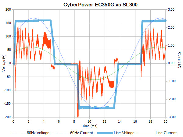
As predicted from the lack of output filtering in the HVDC circuit and output bridge (other than a 0.47µF X1 capacitor), we get a really odd-looking current waveform. The voltage waveform, on the other hand, turns out surprisingly clean with a magnitude of about 160 V, an RMS value of 124.5 V, and a THD of 32%. While my 83 W input power on the UPS matches the 86 W from AC power closely enough to conclude that I have a reasonable sample, such an irregular waveform warrants further investigation to see how much of it may be caused by aliasing.
Zooming In
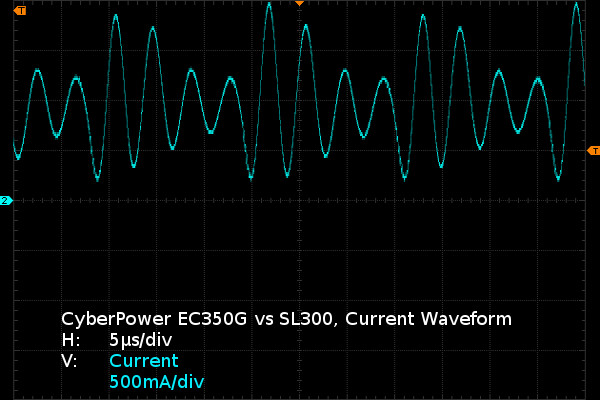
Going from a 20 ms slice to a 60 µs one, the reason for the funky millisecond-scale waveform is an equally funky microsecond-scale waveform. The EC350G’s HVDC converter appears to be operating at roughly 200 kHz, and since there is no filtering at its output, the current gets directly modulated by the SL300’s switching in the neighborhood of 50kHz. This means we can add beats between the two switching frequencies to the list of potential causes of very odd current waveforms and reasons to have a small choke after the output bridge to smooth them out. There is none of that funny business on the BGE90M’s waveform, which has a small HVDC capacitor and a bridge output choke.
Summing It Up
(Doesn't it look much better all straightened out?)
A tiny battery, phone line protection that does nothing except fuse one wire, bent-over capacitors and TO-220 transistors, extremely minimalist UPS output filtering, power supply efficiency that still needs work, and wiring that could really use connectors to tidy things up while reducing the risk that components get mangled during final assembly into the housing.
To be fair on the power efficiency side, the EC350G does have the lowest standby draw of any CyberPower UPS I have done a tear-down of so far (30% less than the 1000PFC) and if you use its ECO mode, then its standby power draw may get eclipsed by savings from cut-off devices.
Aside from its ECO feature, only one polite word comes to my mind to describe the EC350G: unimpressive.
MORE: APC BGE90M-CA UPS Tear-Down
MORE: CyberPower CP1000PFCLCD Tear-Down
MORE: APC BE550G Tear-Down
Follow us on Facebook, Google+, RSS, Twitter and YouTube.
-
Daniel Sauvageau Reply
To me, the battery/batteries are the single most important component in an UPS: if the battery isn't up to snuff, the rest of the UPS is not really worth talking about since it cannot deliver more than the battery can. While the battery isn't bad in absolute terms (it is about even with other brands' batteries), 3.6Ah of nominal capacity drastically reduces the number of cases where it will be viable.18475028 said:Not that promising I guess.
I wouldn't use that to power anything beyond the most basic PC, a PVR/console+TV or other similarly light loads. -
nukemaster I have the polar opposite from Canadian Tire.Reply
40ah of batteries in a 400 watt ups.
400 watts max(320 or less or it only runs for 5 min due to thermal limits)
I would drop in some more images(would be interested in you opinion based on the board), but I do not want to fill a comment thread. I have had it for over 6 years at least(batteries just went). -
JonDol Hey there,Reply
Thanks for the review, as with your other dissections I had good time reading it. Given all these UPS you opened up, maybe you could change the tactic and in a future article tell us how to choose a good UPS ? Moreover, if you team up with your PSU reviewer fellow Aris, something nice could come up, I think. And for the lazy ones like me it would be even better if that ends up recommending some real products that are worth the money.
Thanks!
