CyberPower EC350G UPS Tear-Down
Outlet Strips
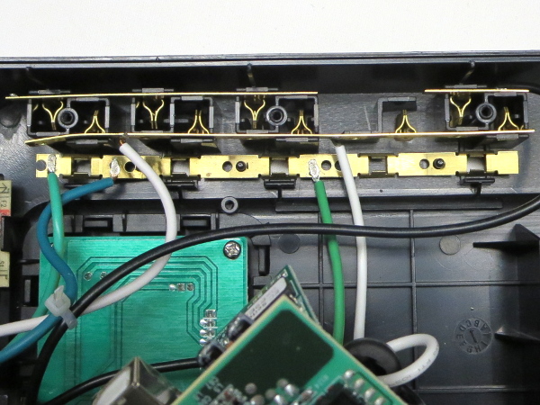
Behind the outlet covers, we find the usual pinchy contact strips for live and neutral, and the torque flaps for ground. The lone piece of contact strip in the upper-right corner is for the always-on surge-only outlet. Its live wire that you see going across the picture goes directly to the breaker.
Nearly every tooling/retaining hole in the ground strip shows signs of kinking. If CyberPower’s employees have to contend with all of those wires and metal strips attached to the board while assembling the UPS, I can imagine how the strips may have been bent a few times along the way.
Jumble To Jungle
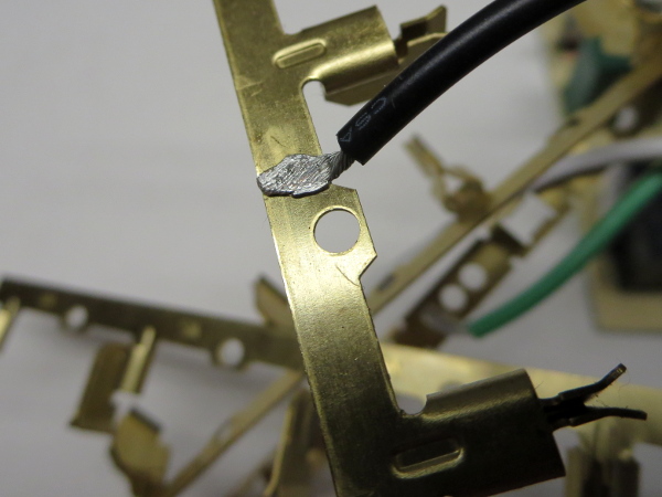
It looks like CyberPower managed to get its wire welding station’s settings and wire preparation right this time around. There are no sign of loose strands, crushing, or pitting. In the background, you can see an overview of the mess of wires and metal strips I had to put up with while working with this UPS. They were as much fun to put back in as they were to take out. In the disassembly and re-assembly process, I added many kinks of my own to these strips.
Protection Racket
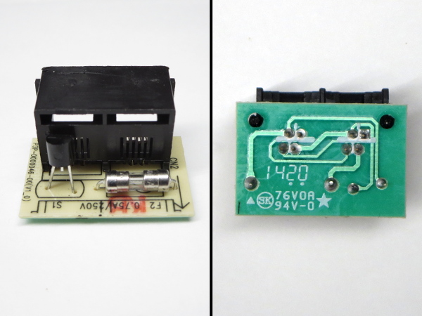
Here’s that phone line protection: the second pair is wired directly from input to output, while the first pair has one wire going right through and another passing through a fuse with a SIDAC straddling the pair. If there is a surge on one wire, the SIDAC will share it with the other, limiting the voltage difference across the pair. There are no MOVs or quaint little diode circuits to ground to divert surge energy.
This circuit won’t protect your telephone devices from much; CyberPower should have skipped it altogether and spent $0.40 elsewhere.
Cleaned Out
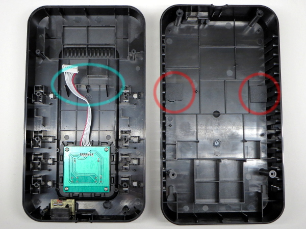
With most of the internals removed, we can clearly see a second battery retaining stop circled in cyan in the top cover with the original battery’s stop just above it. Either CyberPower machines the small stop off for models with a larger battery or has a mold insert to fill it out. On the bottom shell, a pair of pads circled in red have been glued to the back of the wall-mounting slots, presumably to pass the enclosure intrusion part of UL’s certification.
Board Top
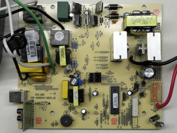
After a minute or two of untangling the wires and strips, I finally managed to get a mostly uncluttered view of the whole board. There are many components bent at odd angles, including multiple TO-220 FETs flapping in the breeze (no doubt casualties of the struggle to assemble units with the mess of wires pre-attached to the board).
Get Tom's Hardware's best news and in-depth reviews, straight to your inbox.
Similar to any other UPS, the EC350G has the same basic building blocks: power input, filtering, and surge suppression occupying most of of the top-left quadrant, the HVDC converter and output bridge covering most of the top-right, control and monitoring filling the bottom-right, and the power supply nesting in the middle.
Board Bottom
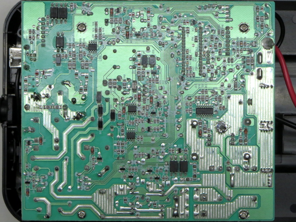
There are many surface-mount chips across the board, including an ST UC3843B PWM regulator for the power supply/charger, an ST SG3525 switching regulator for the HVDC output, some LM358 op-amps, and a handful of opto-isolators. Apart from the micro-controllers on the USB riser and next to the control panel connectors, the rest look like jelly-bean parts.
USB Riser
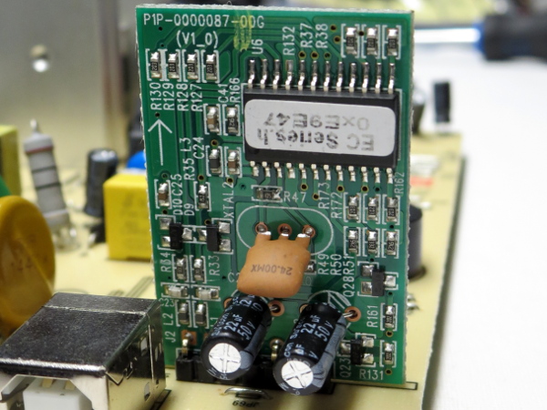
One USB micro-controller with EC series secret sauce loaded into it, two 50 V, 22 µF Su’scon electrolytic capacitors, a handful of transistors and a 24 MHz ceramic resonator is all you'll find on this little board. I am a little surprised to see 50 V caps used on a USB-powered board that only interfaces with the UPS’ main controller over a pair of opto-isolated signals.
In large enough volume, putting 50 V caps everywhere may be more cost-effective and less of a hassle than stocking 22 µF in a handful of different voltage ratings for non-performance-critical circuits.
Writing On The Board
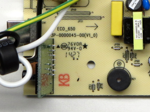
From the writing behind the USB riser, we learn that this same board design is used for CyberPower’s ECO series at least up to the 650VA models, and that my specific board was manufactured in mid-2014.
Input Section
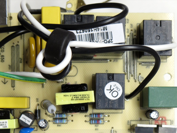
The input protection and switching section contains the typical arrangement of 14471 MOVs (line-neutral, line-ground, and ground-neutral), a current-sensing transformer, and a 470 nF X2-class capacitor. All four relays are “flux-tight” SPDTs from Song Chuan, model 812H for the main power switch and model 833H for the rest.
Speaking of main power, you can hear a relay clicking upon plugging the UPS in, even while it is still off. Suspecting that the main disconnect relay also disconnects the electronics supply, I attempted plugging in the UPS with no battery and got the expected result: no response. This UPS cannot recover from a completely drained battery on its own. It needs enough charge to operate the main relay and related electronics to turn itself on, similar to the SMART1000LCD.
MORE: APC BGE90M-CA UPS Tear-Down
MORE: CyberPower CP1000PFCLCD Tear-Down
MORE: APC BE550G Tear-Down
Power Supply
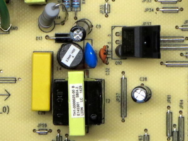
The EC350G’s power supply is a mildly odd affair: there is no high-voltage input filter capacitor. In its place, we find a two-millihenries inductor in series with the transformer and a 100 nF X2 capacitor from the inductor-transformer node to circuit ground. On the bottom side, a pair of 3.3 Ω resistors in parallel provide current sensing to the 3843B for the 600 V/4 A/1.76 Ω ST P4NK60ZFP FET. A handful of other components provide snubbing at various points.
How does an off-line power supply work without a filter capacitor? Time to partially reverse-engineering it.
-
Daniel Sauvageau Reply
To me, the battery/batteries are the single most important component in an UPS: if the battery isn't up to snuff, the rest of the UPS is not really worth talking about since it cannot deliver more than the battery can. While the battery isn't bad in absolute terms (it is about even with other brands' batteries), 3.6Ah of nominal capacity drastically reduces the number of cases where it will be viable.18475028 said:Not that promising I guess.
I wouldn't use that to power anything beyond the most basic PC, a PVR/console+TV or other similarly light loads. -
nukemaster I have the polar opposite from Canadian Tire.Reply
40ah of batteries in a 400 watt ups.
400 watts max(320 or less or it only runs for 5 min due to thermal limits)
I would drop in some more images(would be interested in you opinion based on the board), but I do not want to fill a comment thread. I have had it for over 6 years at least(batteries just went). -
JonDol Hey there,Reply
Thanks for the review, as with your other dissections I had good time reading it. Given all these UPS you opened up, maybe you could change the tactic and in a future article tell us how to choose a good UPS ? Moreover, if you team up with your PSU reviewer fellow Aris, something nice could come up, I think. And for the lazy ones like me it would be even better if that ends up recommending some real products that are worth the money.
Thanks!
