Aerocool Project 7 850W PSU Review
Why you can trust Tom's Hardware
Teardown & Component Analysis
Parts Description
Before proceeding with this page we strongly encourage you to a look at our PSUs 101 article, which provides valuable information about PSUs and their operation, allowing you to better understand the components we're about to discuss. Our main tools for disassembling PSUs are a Thermaltronics soldering and rework station and a Hakko FR-300 desoldering gun. Finally, for the identification of tiny parts we use an Andonstar HDMI digital microscope.
| General Data | |
|---|---|
| Manufacturer (OEM) | Andyson |
| Platform Model | - |
| Primary Side | |
| Transient Filter | 4x Y caps, 3x X caps, 2x CM chokes, 1x MOV |
| Inrush Protection | NTC Thermistor & Diode |
| Bridge Rectifier(s) | 2x GBU1506L (600V, 15A @ 100°C) |
| APFC MOSFETs | 2x Infineon IPP50R140CP (550V, 15A @ 100°C, 0.14Ω) |
| APFC Boost Diode | 1x CREE C3D10060A (600V, 14A @ 135°C) |
| Hold-up Cap(s) | 2x Hitachi (420V, 470uF each or 940uF combined, 2000h @ 105°C, HU) |
| Main Switchers | 2x Infineon IPP50R140CP (550V, 15A @ 100°C, 0.14Ω) Driver IC: Silicon Labs Si8230BD |
| APFC Controller | Champion CM6502S |
| APFC Controller | Champion CM6901 |
| Topology | Primary side: Half-Bridge & LLC Resonant Controller Secondary side: Synchronous Rectification & DC-DC converters |
| Secondary Side | |
| +12V MOSFETs | 8x Infineon BSC010N04LS (40V, 100A @ 100°C, 1.0 mΩ) |
| 5V & 3.3V | DC-DC Converters: 2x CSD86350Q5D power blocks PWM Controller: 2x Anpec APW7073 |
| Filtering Capacitors | Electrolytics: Nippon Chemi-Con (105°C, KY, KZE), 1x Nichicon (4-10,000h, 105°C, HE) Polymers: 5x Nippon Chemi-Con, 6x FPCAP |
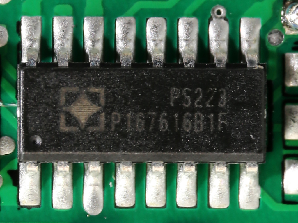
| Supervisor IC | SITI PS223 (OVP, UVP, OCP, SCP, OTP ) |
| Fan Model | 140mm LED fan (CD1425M12F, 12V, 0.24A, 1623 RPM, FDB) |
| 5VSB Circuit | |
| FET / Rectifier | 1x APEC AP92U03GM / PFR10V45CT (45V, 5x 2A, 0.4V @ 125°C) Driver IC: MIC4426 |
| Standby PWM Controller | Sanken STR-A6069H |
| -12V Circuit | |
| Rectifier | Kodenshi Auk SN7912PI (-12V, 2.2A @ 25°C) |
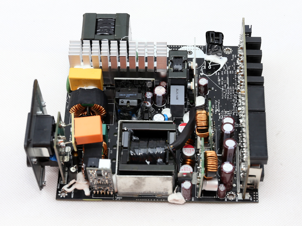
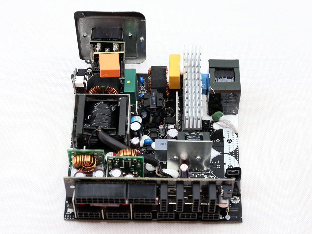
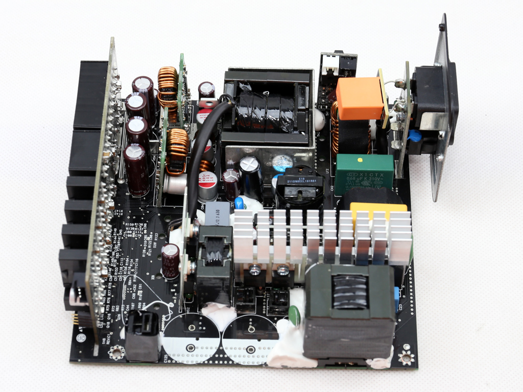
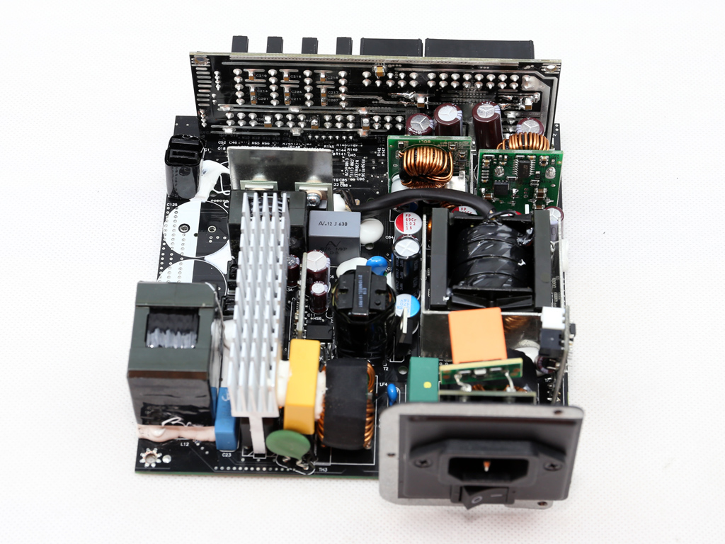
The ACP-850FP7 is based on Andyson's high-end platform, also utilized in the manufacturer's Titanium-class N700 model. But besides higher capacities and better ripple suppression, Aerocool also wanted fully modular cables, so keeping efficiency at such high levels wouldn't be easy. Moreover, it'd have a big impact on manufacturing costs.
What we end up with is a modern design that sports a half-bridge topology and LLC resonant converter on the primary side. On the secondary side, we find a synchronous rectification scheme for the +12V rail, along with DC-DC converters for generating the minor rails. All filtering caps are provided by Japanese manufacturers and are of good quality. The same applies to the primary- and secondary-side FETs (besides the filtering caps, FETs play a huge role in a PSU's reliability).
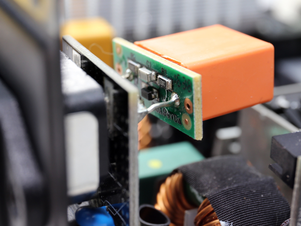
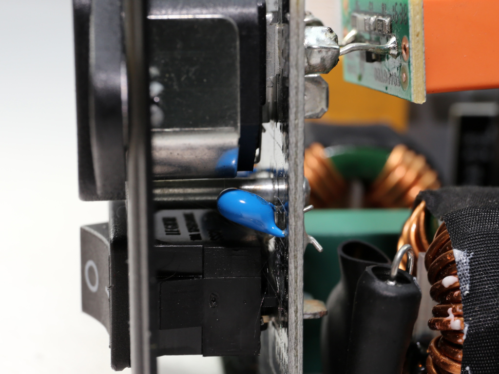
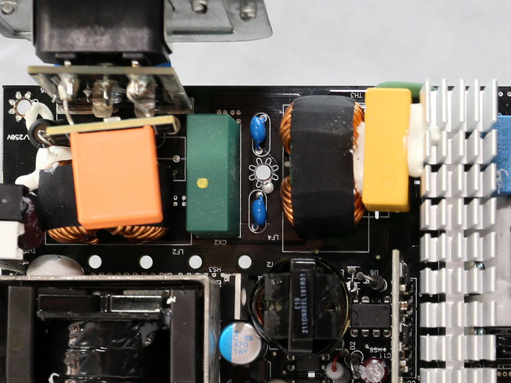
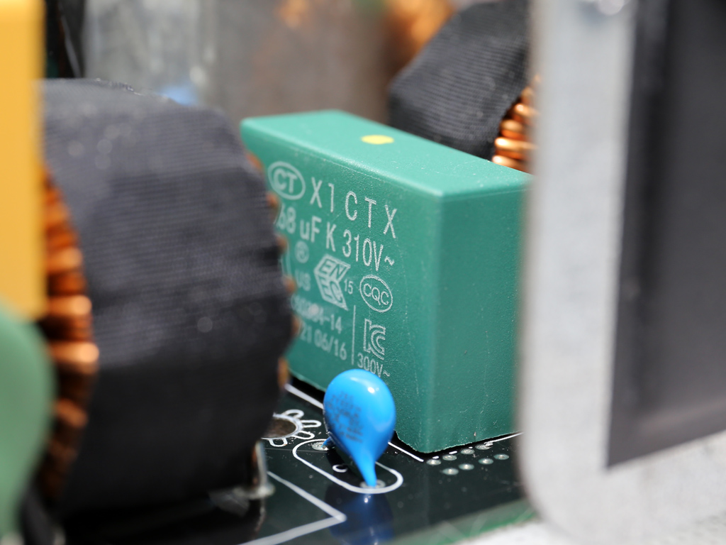
The first part of the transient filter is on a small PCB that also hosts the AC receptacle. It includes two Y caps and one X cap. The filter continues on the main PCB with two more Y caps and two X ones, two CM chokes, and an MOV.
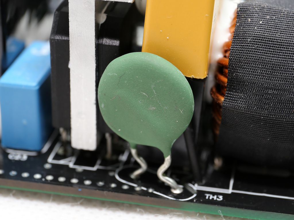
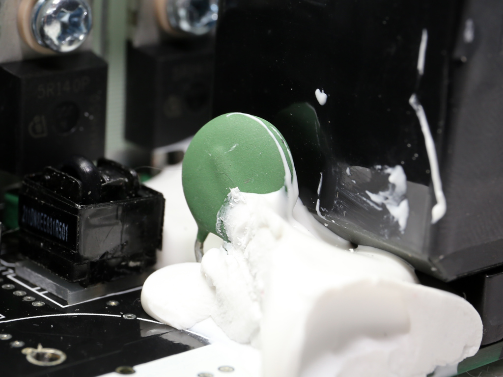
There are two NTC thermistors, one close to the transient filter, supported by a bypass relay, and a second one in the APFC section.
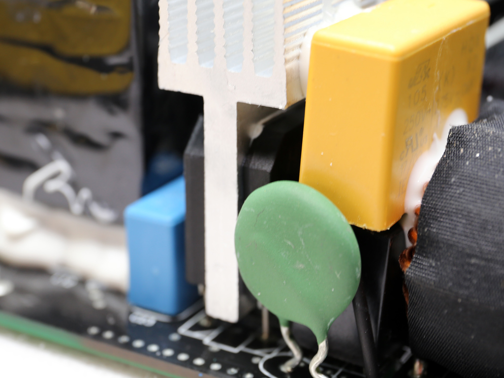
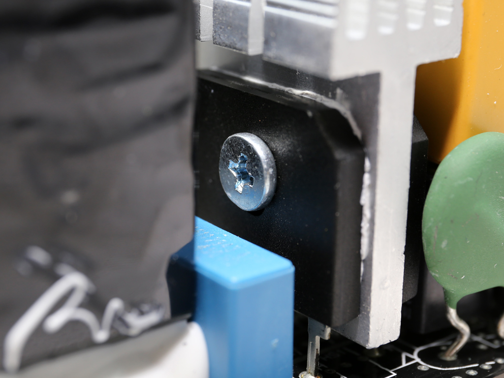
A pair of bridge rectifiers (2x GBU1506L) can handle up to 30A of current, which is quite a lot for an 850W PSU.
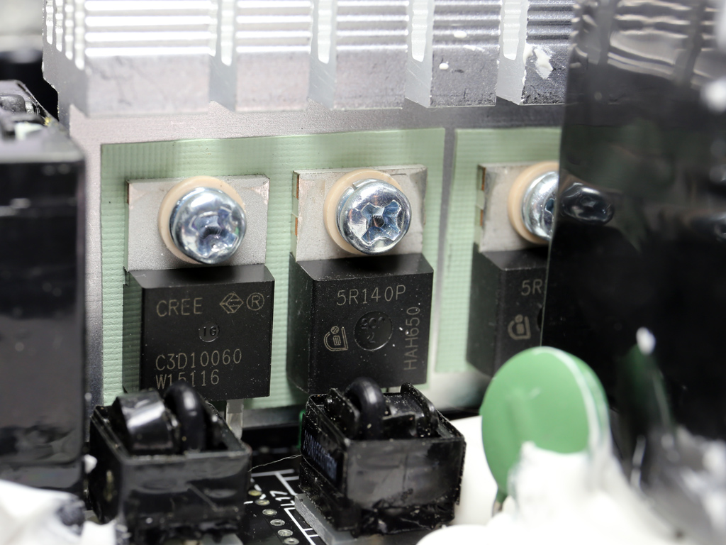
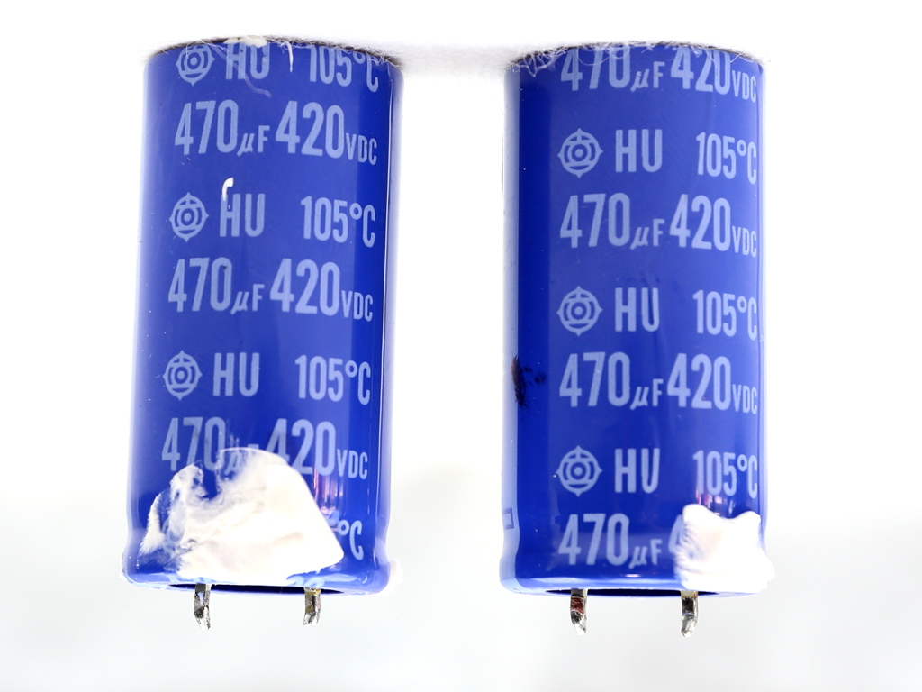
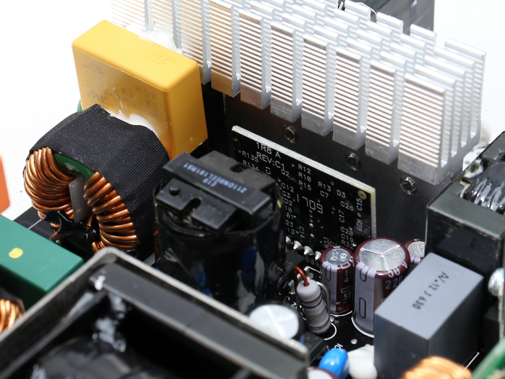
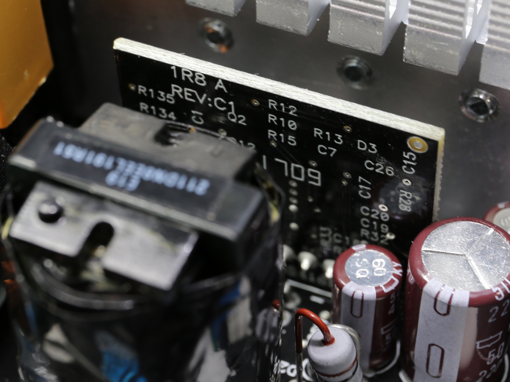
The APFC converter uses two Infineon IPP50R140CP FETs along with a single CREE C3D10060A boost diode. Two bulk caps are provided by Hitachi and belongs to its HU series. Their combined capacity, 940uF, is enough for the needs of this PSU. The APFC controller is a Champion CM6502S IC, and it's installed on a small vertical daughterboard located close to the APFC's heat sink.
Get Tom's Hardware's best news and in-depth reviews, straight to your inbox.
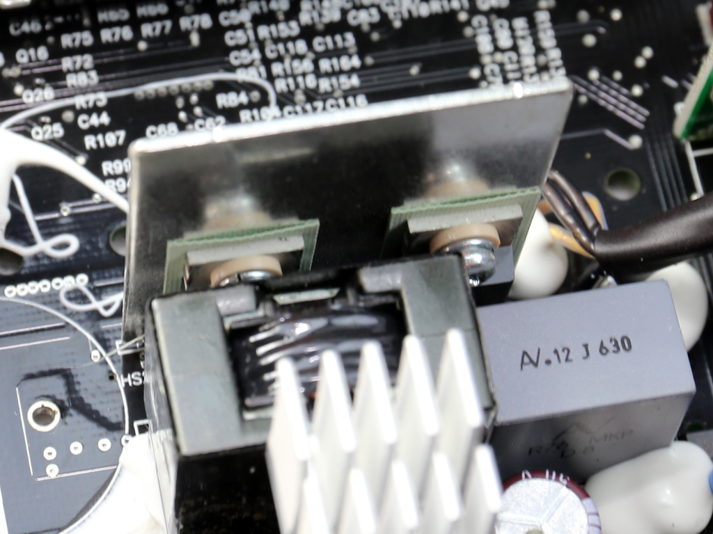
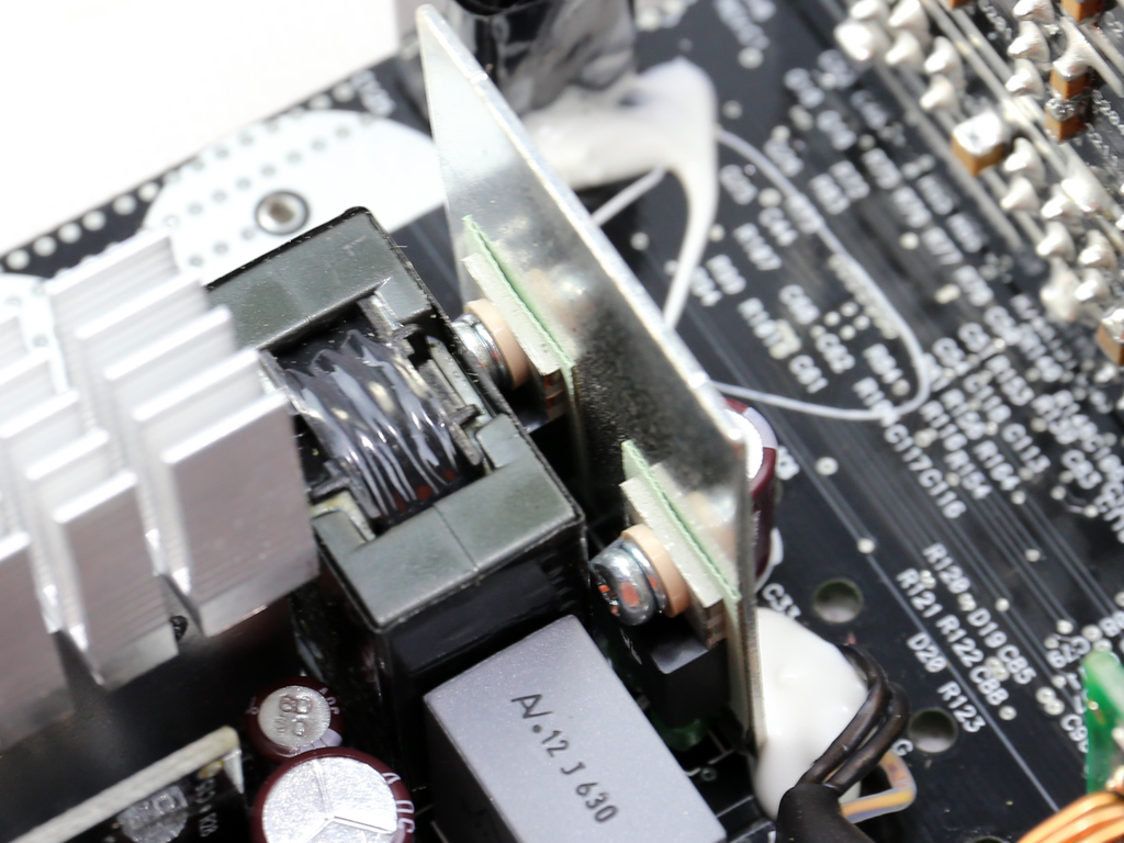
Both primary FETs, two Infineon IPP50R140CPs, are bolted onto a small piece of metal that acts as a heat sink. Those FETs are configured into a half-bridge topology. An LLC resonant converter is also used to boost efficiency. The LLC resonant controller is Champion's famous CM6901, which is installed on the solder side of the PCB. Next to the CM6901 we also spot a Silicon Labs Si8230BD driver IC, used for controlling the primary FETs.
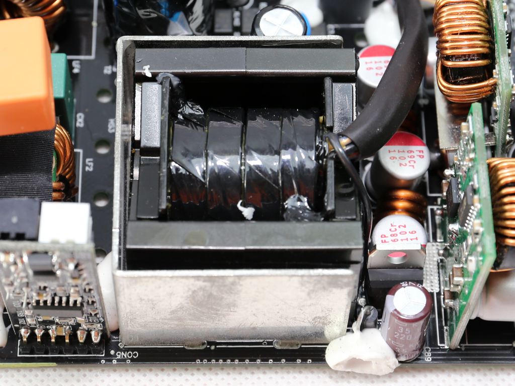
The main transformer is nearly surrounded by a metallic shield/heat sink. It's fairly compact given this unit's capacity, so we can assume it employs a special design.
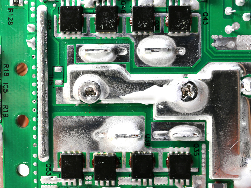
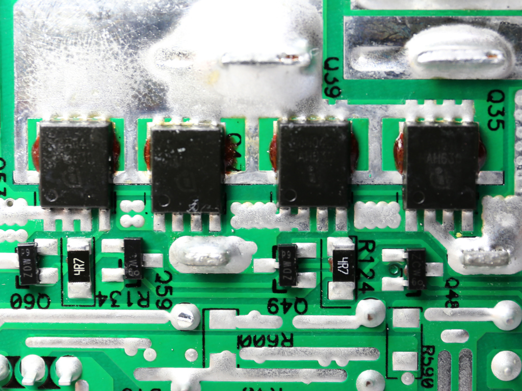
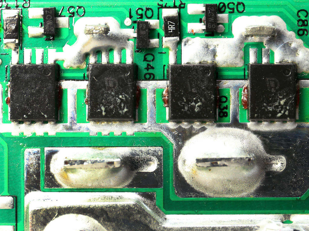
Eight Infineon BSC010N04LS FETs regulate the +12V rail. These FETs are cooled by the chassis through a thermal pad that facilitates heat transfer.
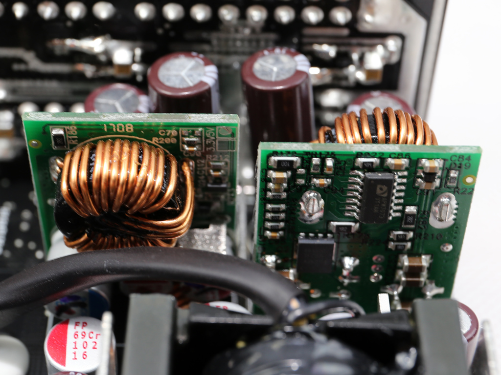
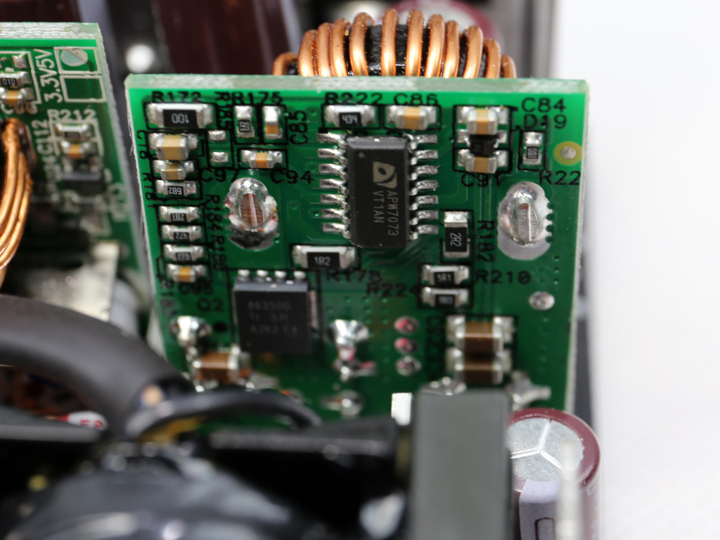
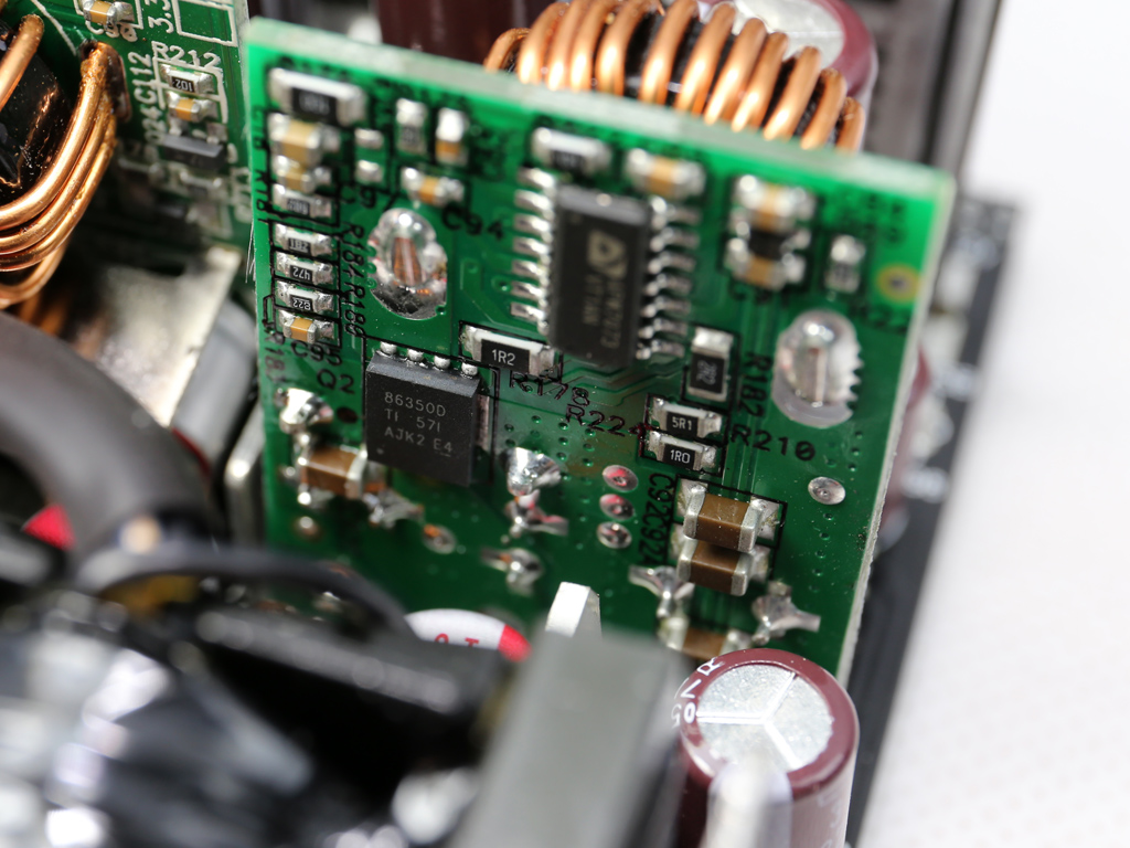
Both DC-DC converters use two CSD86350Q5D power blocks and a pair of Anpec APW7073 PWM controllers.
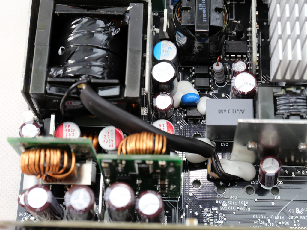
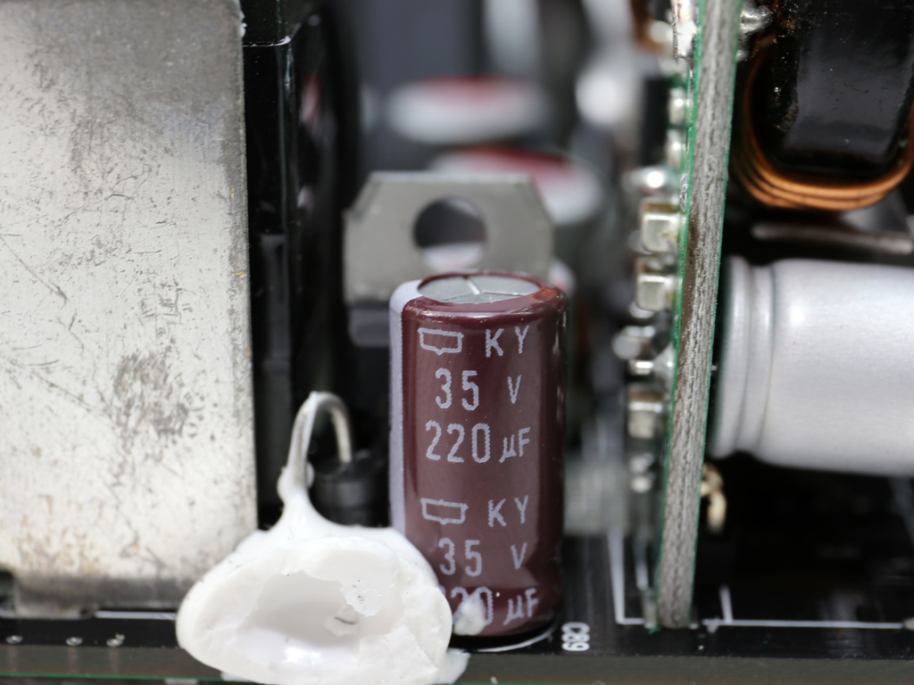
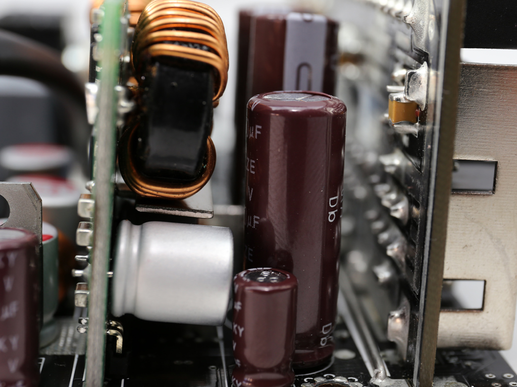
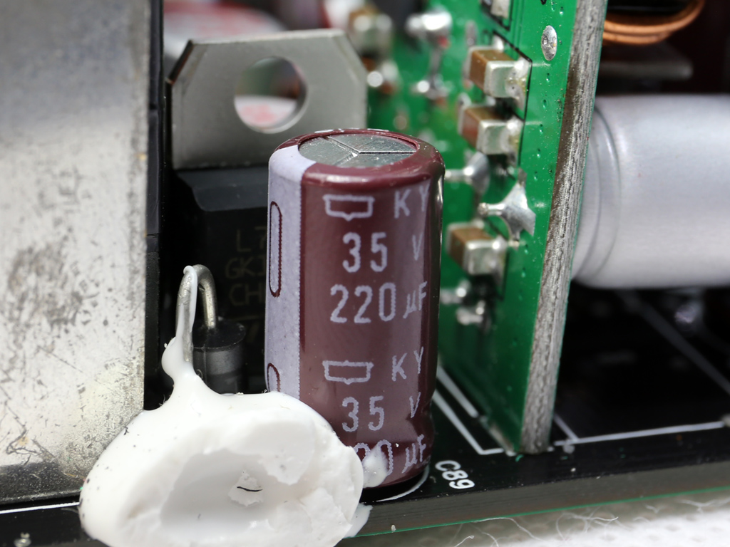
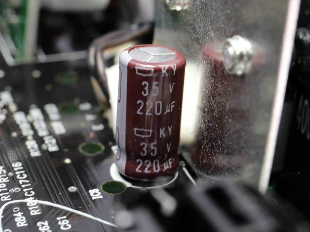
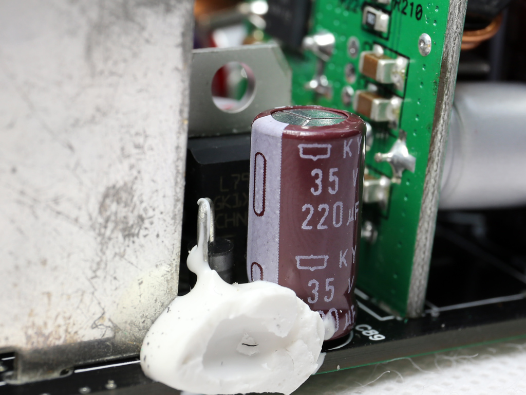
A number of Chemi-Con KY and KZE electrolytic caps, along with a Nichicon, are used for ripple filtering purposes. They're accompanied by almost a dozen Chemi-Con and FPCAP polymer caps.
A SITI PS223 is installed on the board's solder side. It supports all necessary protection features, including OTP. In our opinion, it's one of the best (and most complete) supervisor ICs.
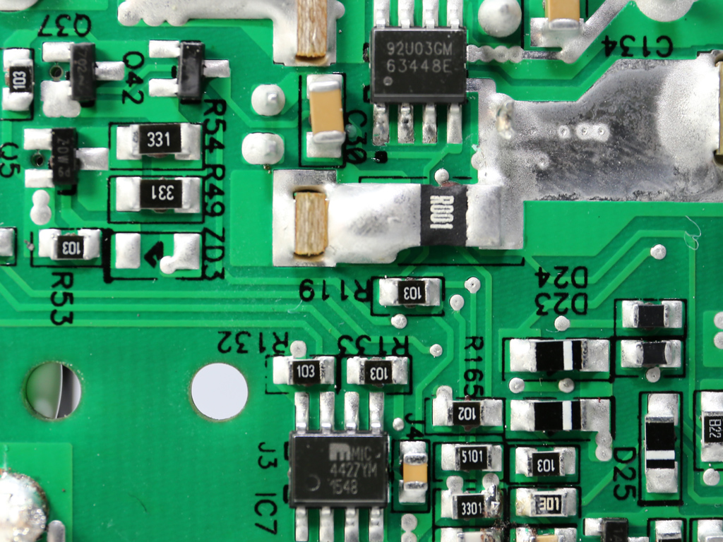
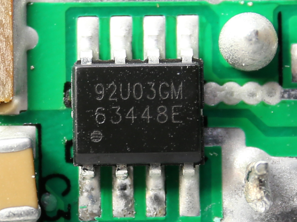
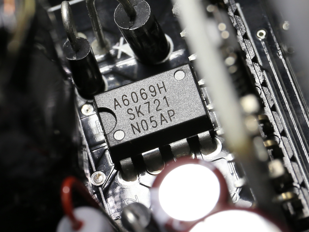
The 5VSB circuit uses an APEC AP92U03GM FET and PFR10V45CT SBR combo. A MIC4426 driver IC is most likely used to control the FET. Finally, the standby PWM controller is a Sanken STR-A6069H.
A KODENSHI AUK SN7912PI rectifies the -12V circuit.
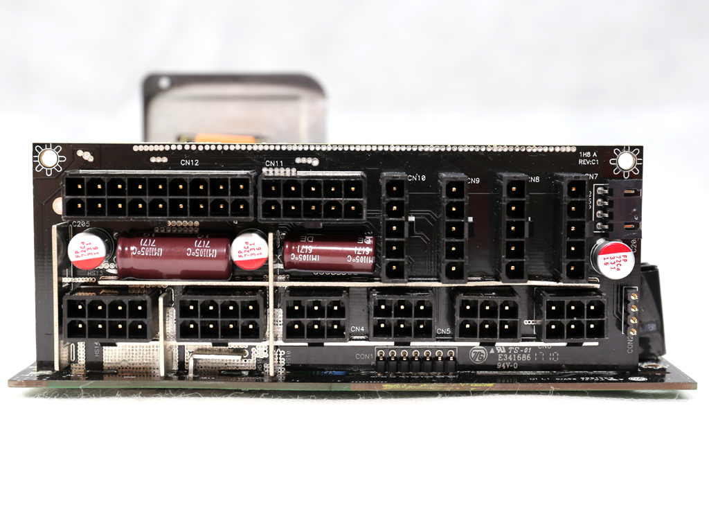
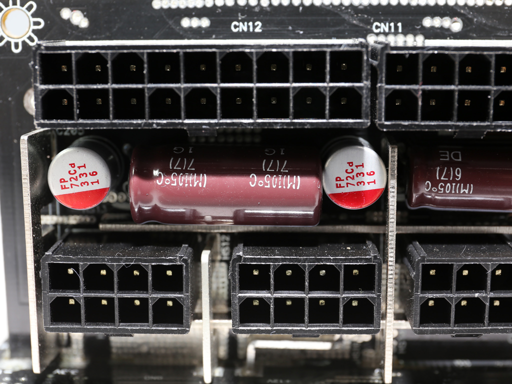
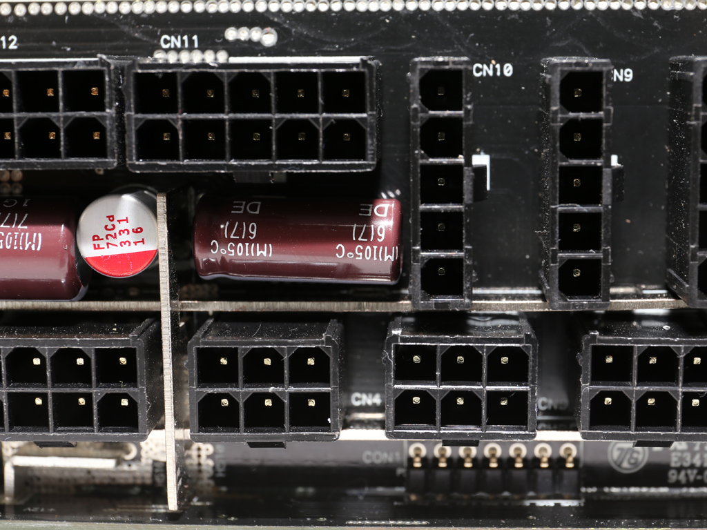
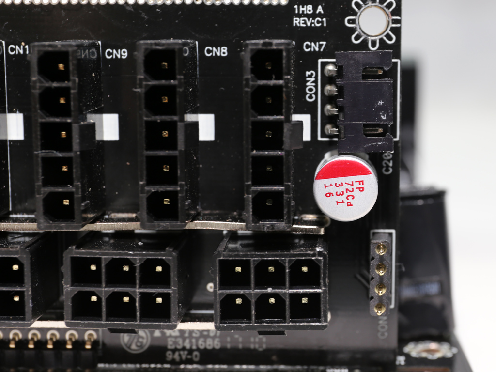
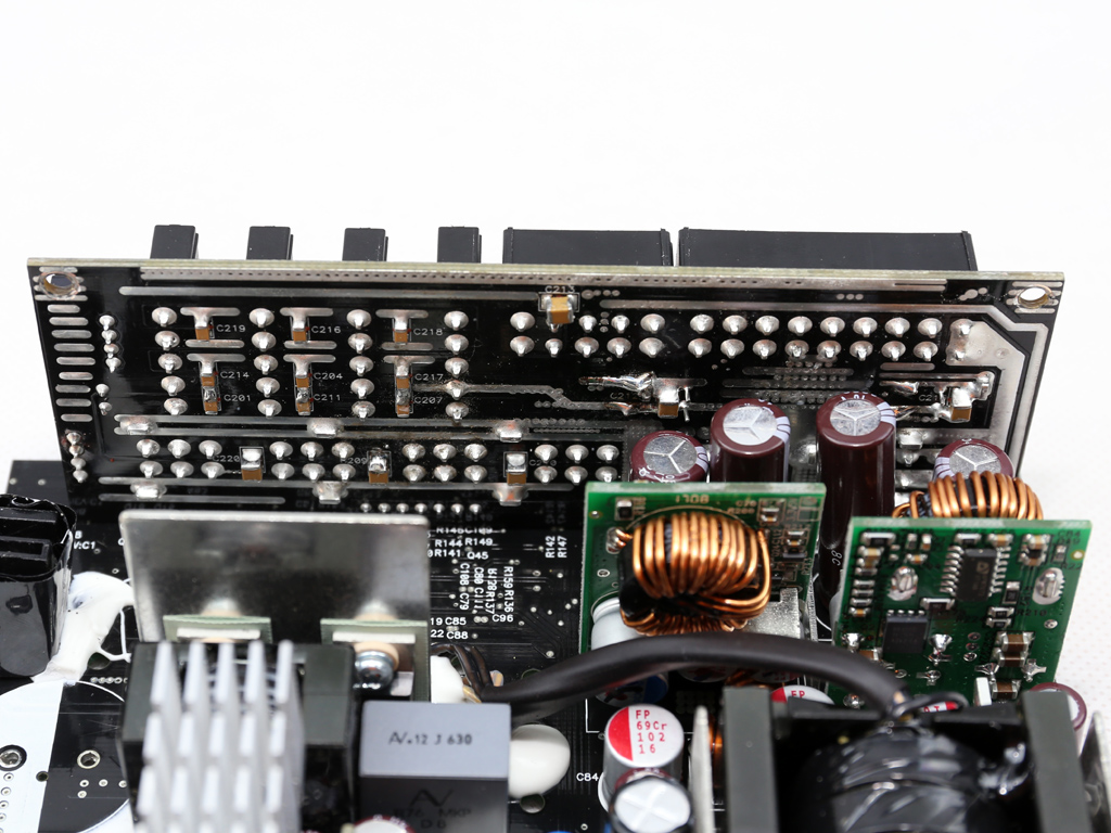
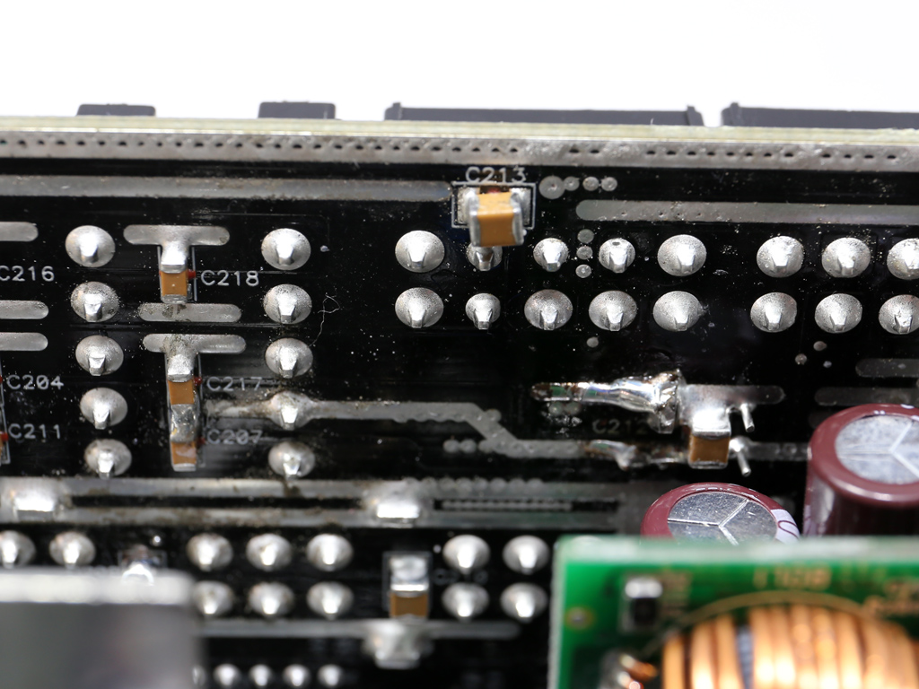
Two Chemi-Con electrolytic caps and three polymer ones (by FPCAP) on the modular board's primary side provide an extra ripple-filtering layer. On the back of the modular board, we find many small polymer caps.
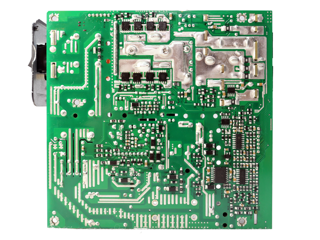
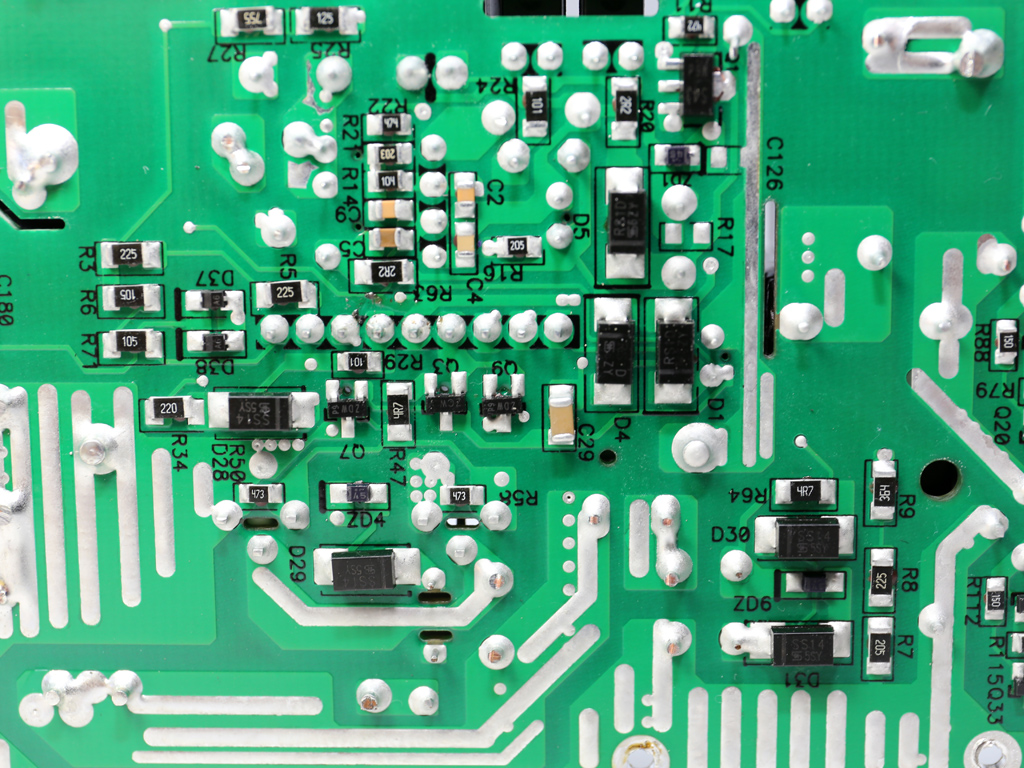
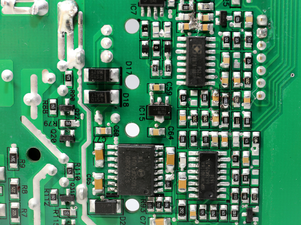
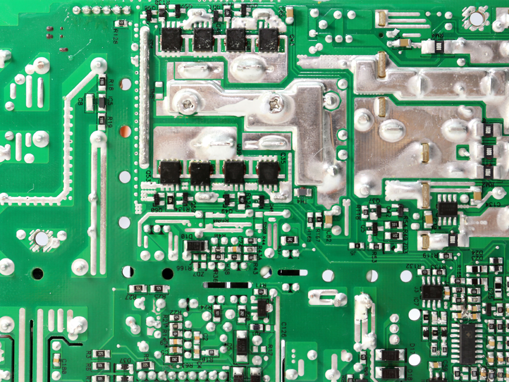
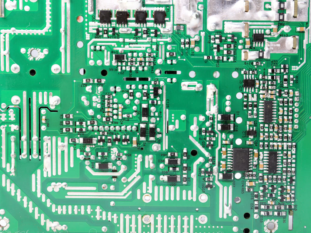
The soldering quality is pretty good; we don't have anything to complain about.
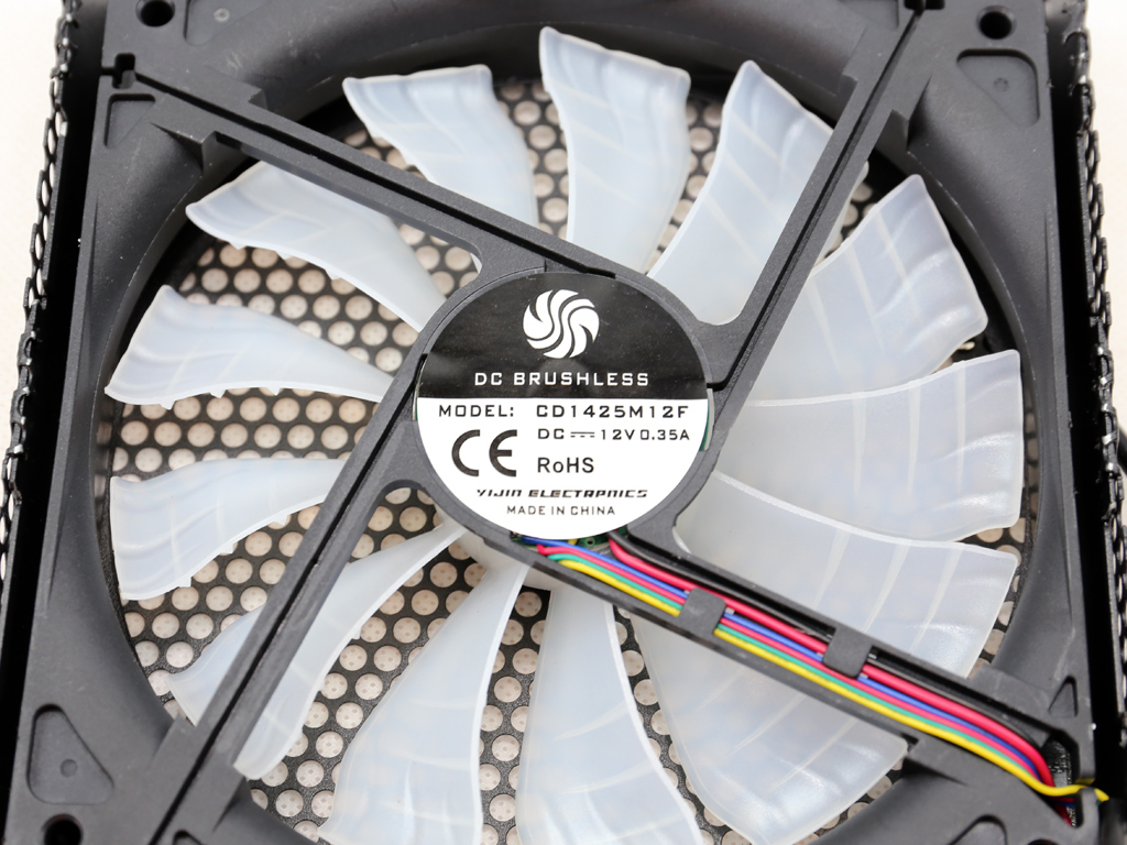
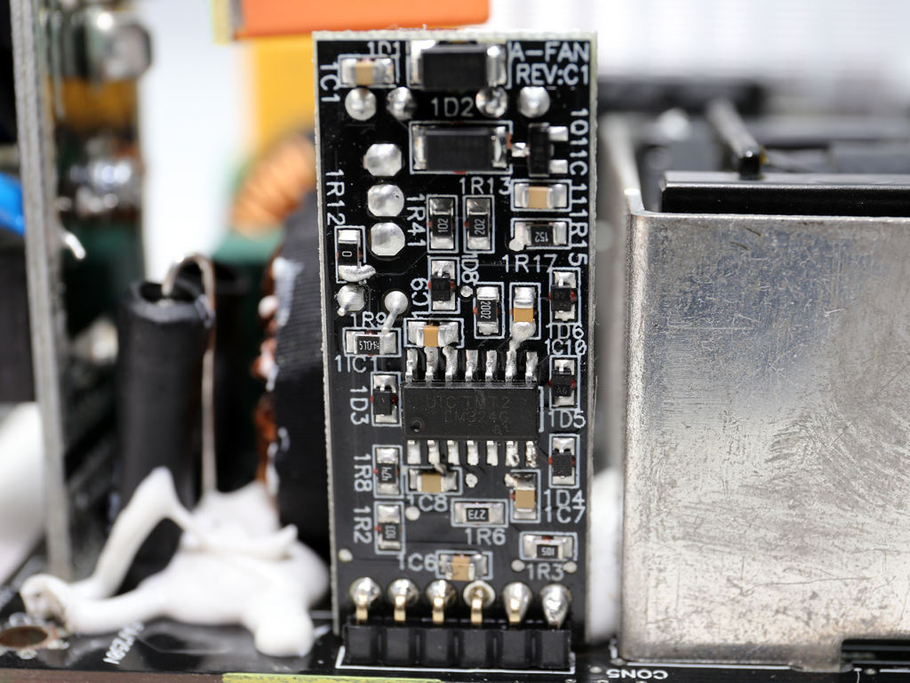
The 140mm cooling fan (CD1425M12F, 12V, 0.24A, 1623 RPM) uses a fluid dynamic bearing. This is a low-speed fan controlled by a conservative profile. It employs a Unisonic LM324G IC.
MORE: Best Power Supplies
MORE: How We Test Power Supplies
MORE: All Power Supply Content
Current page: Teardown & Component Analysis
Prev Page Packaging, Contents, Exterior & Cabling Next Page Load Regulation, Hold-Up Time & Inrush Current
Aris Mpitziopoulos is a contributing editor at Tom's Hardware, covering PSUs.
-
vgray35 And lo and behold another elephant enters the room, except here we have a touch of pesky arrogance thrown into the mix, where $165 admits a product without fan failure and 12V over current protection. But that is really not the least of the woes. It is high time Tom's Hardware calls out these manufacturers for producing inefficient power supplies, and stop this nonsense of labeling as high efficiency a peak of 92% (88% at full load), and certainly fanless mode is not difficult to achieve and should be part of all PS and hardly rises to the level of a unique feature. If these features are missing then the PS is not qualified for the use in computers – period. Let us not accept mediocrity as acceptable, and it is high time PS become true commodity level components. Fundamental Power Supply improvements look for increased efficiency and reduced cost through improved Power Electronics Topologies, and the fact of the matter is modern power supplies are grossly inefficient, and are largely founded upon old Buck converter technology and its derivatives (forward, bridge, etc), including the resonant variants like the LLC resonant converter based on half/full bridge drivers. Despite great strides made over 60y these variants still belong to the same family of topologies, insisting on inserting an air gap into an AC-inductor to a convert it to a DC-inductor so it passes a large DC current, and hard switching of large currents. Even the various resonant and zero current switching variants have not delivered on ultra high efficiency, or high performance step response settling times. These are not bold claims as I will attempt to describe below, and the common element in these topologies limiting performance is largely inductive energy storage – the infamous ferrite cored inductor (i.e. transformers with air-gaps are not true transformers, but energy storage devices). What we have is 850W accompanied by 120W of waste heat at full load (~88% eff.) and 32W waste heat at 50% load (~92.5% eff.), when 98% eff. could yield 17W of waste heat at full load. So why are manufacturers asleep at the switch? What about an ATX PS with a length of 50mm instead of 160mm @ 650W where temperature never exceeds 20 deg above ambient at full load, with motherboard VRM sporting 99% eff. and 3 GPUs with VRMs at 99% efficiency? This is not pie in sky rhetoric here as shown below, and power supplies could come to < $40 sporting ultra high efficiency for 1kW units.Reply
The Buck converter was invented during the 1950's and improvement in high frequency switching devices has largely hidden the failings of this topology, including its various variants, and despite improvements a lot of waste heat still accompanies the power conversion process. Looking at the limiting factors in this process reveals without exception modern topologies use the air-gapped inductor for energy storage and power transfer, which is the root cause of bad efficiency, large size and poor energy transfer capability. The hope of multi-Mega Hertz switching to reduce size has been proven futile, as this brings with it reduced operating core flux density at elevated frequencies, increased core losses and switching losses, which offset much of the championed size reductions. Several problems underpin inductive energy storage topologies, in that currents are hard switched causing EMI noise that must be filtered out, and resonant topologies that reduce switching losses have not alleviated the underlying issue of inefficient inductive energy storage, such as for example the LLC resonant converter. There is much more that could be said on this topic, but suffice it to say 90% efficiency is the norm here, with slightly better efficiency obtained only at the price of increased size. But yet new topologies are now available that will allow the Buck converter and its derivatives to be retired - new topologies that have already been invented over the course of the last decade. Several new elements have emerged that now offer efficiencies in the 98% to 99.5% range which reduces waste heat by over 80%. Why then are we still plagued by the poor performance that derives from inductive energy storage?
First and foremost capacitive energy storage is by far more compact by 2 orders of magnitude, and coupled with a new PWM-resonant switching topology that allows single cycle response settling times, and zero current switching, increases dramatically efficiency and overall performance with >70% reduction in size. An inductor and capacitor resonant network is still in play here, but also introduces a new hybrid resonant switching and resonance scaling, which allows resonant capacitance to be increased by 2 orders of magnitude, with a corresponding reduction in the size of the inductor component, and what's more this is now achievable at 50kHz frequency instead of MHz frequencies; which saves considerably on switching losses which still maintaining minuscule size. Power supply size reduction approaches >70% in eliminating ferrite cores, and >80% in large heat sinks with the advent of ultra efficiency, with a corresponding cost reduction. For example the inductor has no ferrite core (i.e. air-cored) and becomes a 5 mm length of copper wire, while a bank of ceramic chip capacitors in parallel are minuscule compared to today’s air-gapped DC-inductors. These new technologies also offer reduced operating flux densities for high frequency isolation transformers, which operate purely as AC transformers with no need for air-gaps to pass DC current. Here is a link to an article describing some of these new elements.
Ultra high 99.5% peak efficiency
http://www.powerelectronics.com/power-management/step-down-dc-dc-converter-eliminates-ferrite-cores-50khz-enabling-power-supply-chip
See section on: 98% Efficient Single-Stage AC/DC Converter Topologies
http://www.power-mag.com/pdf/issuearchive/46.pdf
An ATX PSU at 98% efficiency with a single stage PFC and DC-DC converter, generating much less EMI noise than today’s PSU is achievable. A motherboard VRM at 99% efficiency using a single stage for each of the CPU, GPU, and memory components, with response settling times an order of magnitude faster than the multi-stage buck converters, is achievable. The GPU using a similar VRM, net waste heat within a computer case is reduced by over 80%. Platinum and Titanium power supplies do not provide ultra high efficiency >98% and are monstrosities in terms of size. The ability to eliminate ferrite cores even at 50kHz is a panacea of Power Electronics Converters. An 850W PS driving a system with 3 GPU could be reduced to 600W, with 3*25W less GPU waste heat, 70W less ATX PS heat, 60W less motherboard VRM waste heat – a total of 200W of waste heat saved at full load. There is really no reason why memory modules could not incorporate their own VRM on each memory module, so small is this new switching topology. The entire VRM is now just a single chip incorporating controller and power stage.
The PS efficiency standards are way out of date, and manufacturers are not sufficiently diligent about advancing the art, and so surely we should object when they present us with these high priced monstrosities. On does not need better standards to adopt improved power electronics topologies.
Sorry for such a long post, but somebody had to speak up on this issue.
